STRESS-STRAIN RELATION AND NONLINEAR BEHAVIOR OF
CIRCULAR CONFINED REINFORCED CONCRETE COLUMNS
Tavio
Lecturer, Department of Civil Engineering,
Sepuluh Nopember Institute of Technology (ITS), Surabaya, Indonesia E-mail: tavio@its.ac.id
Arbain Tata
Lecturer, Department of Civil Engineering, Khairun University, Ternate, Maluku Utara, Indonesia
ABSTRACT
This paper presents a nonlinear finite element modeling and analysis of circular normal-strength reinforced concrete columns confined with transverse steel under axial compressive loading. In this study, the columns were modeled as discrete elements using ANSYS nonlinear finite element software. Concrete was modeled with 8-noded SOLID65 elements that can translate either in the x-, y-, or z-axis directions from ANSYS element library. Longitudinal and transverse steels were modeled as discrete elements using 3D-LINK8 bar elements available in the ANSYS element library. The nonlinear constitutive law of each material was also implemented in the model. The results indicate that the stress-strain relationships obtained from the analytical model using ANSYS are in good agreement with the experimental data. This has been confirmed with the insignificant difference between the analytical and experimental, i.e. 1.011 and 1.306 percent for the peak stress and the strain at the peak stress, respectively. The comparison shows that the ANSYS nonlinear finite element program is capable of modeling and predicting the actual nonlinear behavior of confined concrete column under axial loading. The actual stress-strain relationship, the strength gain and ductility improvement have also been confirmed to be satisfactorily.
INTRODUCTION
One of several reasons that cause the collapse of a multi-story building or bridge structure is the failure of the supporting members to withstand the earthquake loading. The failure of these members is mostly due to the lack of shear-resisting capacity and insufficient ductility provided by little amount of transverse steel. It is well known that the ductility of a reinforced concrete column plays a very important role in preventing such a failure. That is why the study on the ductility of a reinforced concrete column has been developing at a fast pace in the last two decades in many countries worldwide. One of the effective ways to improve the ductility of a column is by introducing sufficient lateral reinforcement as confining steel for concrete core in a column. This effort is primarily intended to delay the sudden collapse of a column and force it further to fail in a ductile manner.
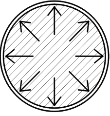
Fig. 1. Effective confined regions in a concrete core of a circular column cross section
(1) the spacing or pitch of transverse steel or spiral is denser; and
(2) the more number of longitudinal steel is used and well distributed around the perimeter of the column section.
Numerous researches have been conducted earlier to study the effectiveness of confinement in improving the ductility of reinforced concrete columns. Some experimental tests carried out by several previous researchers include the studies conducted by Cusson and Paultre [1], Saatcioglu and Razvi [2], and Assa, Nishiyama, and Watanabe [3], etc. [4-11]. Cusson and Paultre [1] carried through the experimental tests on short columns with high-strength concrete and proposed a stress-strain model of ductile confined concrete. Saatcioglu and Razvi [2] tested and observed the ductile behavior of confined concrete columns with the strength up to 120 MPa. Assa, Nishiyama, and Watanabe [3] also conducted similar tests on confined short columns and examined their ductile behaviors, and there are still many more studies conducted by others [4-11]. The numerical approaches conducted by previous researchers were mostly developed on empirical basis. This is due to the complex parameters involved in deriving the constitutive law of confined concrete. Though, some researchers had made many attempts to come up with an accurate analytical stress-strain model of confined concrete, they always ended up with a fine-tuning measure in matching up the analytical results with the experimental data obtained from their tests.
In this paper, the authors propose an analytical procedure for predicting the actual stress-strain relationship of both confined and unconfined circular concrete column under axial concentric loading. The procedure is valid for circular concrete columns with transverse steel or spiral of various spacing or pitch. To establish the analytical model, the authors have selected one of the most popular finite element-based commercial software, i.e. ANSYS [12] that capable of modeling the nonlinear behavior of both reinforced concrete beams and columns [13-18]. However, none of the work conducted previously includes reinforced concrete columns confined by transverse steel or spiral. The proposed procedure has been verified with four column specimens confined by various spacing of transverse steel representing light to heavy confinement [19]. The analytical stress-strain curves obtained from the proposed procedure are shown to be in close agreement with the experimental data from literature [19].
RESEARCH SIGNIFICANCE
columns not only in the linear-elastic region, but furthermore also in the nonlinear post-elastic region. The authors wish that this economical procedure can be used to provide an alternative tool for researchers or structural engineers in investigating various types of structural concrete elements in the future.
FINITE ELEMENT PROCEDURE
The finite element procedure implemented in this study is developed using the available element types from ANSYS element library [12]. The concrete is modeled using SOLID65 element type, whereas the steel for longitudinal and transverse reinforcements is modeled with LINK8 element type. By adopting and combining these two element types, the reinforced concrete column model was developed.
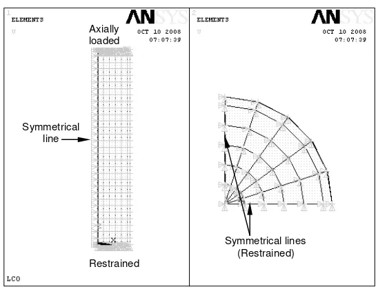
The column model was subjected to an axial compressive loading on their top face simulating the actual loading applied in the tests [19], while the bottom side was restrained. The loading procedure can be elaborated in the following sequence: (1) for the ascending branch (up to peak stress): the column model is subjected to a step-by-step incremental axial pressure on its entire top surface; then (2) for the descending portion (beyond the peak stress): the loading was then switched into the displacement-mode control by applying a step-by-step incremental displacement on its top surface.
Fig. 2. Boundary conditions of a symmetrical quarter of a column model: (a) elevation; (b) cross section
DETERMINATION OF MODEL
The analytical models were constructed according to the actual column specimens in literature [19] as shown in Fig. 3. The column models had a typical cross sectional diameter of 500 mm with the height of 1500 mm. The concrete cover was 20 mm. The first column specimen was made from plain concrete, namely specimen LS0 (Fig. 3). The three remaining column specimens had various spacings and diameters of transverse steel, i.e. specimens LS1, LS2, and LS3 (see Fig. 3). The mechanical properties of each specimen used for validation in this study were adopted in developing the analytical models to better reflect the actual behavior of each column specimen.
Table 1. Summary of geometrical and mechanical properties of the column specimens
LC0
We ld We ld
We ld
We ld We ld
We ld
LC1 LC2 LC3
Fig. 3. Geometrical properties of column specimens LS0, LS1, LS2, and LS3 used for model validation
MATERIAL PROPERTIES
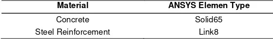
Table 2. Material types for modeling the column specimens
Material ANSYS Elemen Type
Concrete Solid65 Steel Reinforcement Link8
To develop the proposed analytical model in the ANSYS software, the following data is required to be prepared for the input data prior to the analysis. The material properties of each element type can be elaborated in the following details to reflect the actual mechanical and physical properties of the column specimens. Following is the summary of the concrete properties required for input data:
1) stress-strain relationship of concrete (σc–εc); 2) modulus of elasticity of concrete (Ec);
3) specified compressive strength of concrete (fc′ = 28.8MPa); 4) modulus of rupture of concrete (fr);
5) poisson ratio of concrete (νc = 0.2) ;
6) concrete density (γc);
and for the reinforcing steel, it can also be summarized as follows: 1) stress-strain relationship of reinforcing steel (σs–εs);
2) specified yield strength of longitudinal steel (fyl = 235MPa);
3) specified yield strength of transverse steel (fyh = 295MPa); 4) modulus of elasticity of reinforcing steel (Es);
B
Fig. 4. Stress-strain relationship of concrete proposed by Popovics [20,21]
The stress-strain relationship of concrete proposed by Popovics [20,21] as a part of the constitutive laws adopted in the proposed model can be described by the following equations:
B
Fig. 5. Stress-strain relationship for reinforcing steel proposed by Park and Paulay [22]
For reinforcing steel, the adopted stress-strain relationship in the proposed model is that proposed by Park and Paulay [22]. The related equations used to develop the constitutive laws in the model are as follows:
r = εsu – εsh (13)
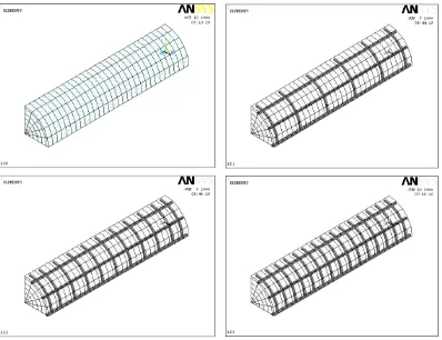
ELEMENT MESHING
After preparing all the input data of material and geometrical properties, the column models were divided into small elements. The meshing results of all column specimens used for model validation are shown in Fig. 6. Column specimen LS0 was also meshed with similar pattern as three other column specimens shown in Fig. 6. For columns reinforced with steel rebar, it is worthwhile to notice that the meshing was created according to the locations of reinforcing bars, either the longitudinal or transverse reinforcement, as well as the column specimen cross-sectional perimeter. By this way, both SOLID65 and LINK8 elements [12] are fully interconnected each other forming a single solid column model that can simulate the actual behavior of the column specimen.
LOADING PROCEDURE
analysis. When the automatic time step option is selected, it will automatically resize the number of the sub-steps in each load step when it fails to reach a convergent solution. This process keeps repeating until it provides a convergence value.
When the load has reached its peak value, the load control mode was switched into the displacement control mode. The displacement control mode was set into several displacement steps corresponding to the experimental data. Using the automatic time steps, the column specimen was displaced until failure. The objective of using this kind of mode is to obtain the descending branch of the stress-strain curve of the column specimens under axial loading. The incremental nonlinear equation can be written as follows:
( )
u uK ∆ = ∆P (14)
where ∆u and ∆P describe the unknown incremental displacement and the given incremental applied load vectors, respectively.
equilibrium ∆Ri+1 = ∆P – K(ui+1)∆ui+1. This procedure is repeated until the convergent
solution is obtained.
Fig. 6. Element meshing of quarter column specimens LC0, LC1, LC2, and LC3
NUMERICAL IMPELEMENTATION
The quantitative implementation of the finite element procedure used in the ANSYS software [12] is based on the principles of virtual work or the postulation of minimum potential energy in the assembly of the elements as formulated the following equilibrium equation:
[ ]
{ } { } { } { }
{ }
{ }
0 00+ − =
+ +
+ F F F F R
d
K p s ε σ (15)
The stiffness matrix [K],
[ ]
K =∑∫
[ ] [ ][ ]
BT D Bdv (16)LC0 LC1
The nodal force due to the surface load,
The nodal force due to the initial strain,
{ }
=−∑∫
[ ] [ ]
{ }
The nodal force due to the initial stress,
{ }
=−∑∫
[ ] [ ]
{ }
ANSYS software uses Newton-Raphson (N-R) method [12] to obtain the convergent solution of the nonlinear equilibrium iterative equation to develop the stiffness matrix of the column model.RESULTS AND DISCUSSIONS
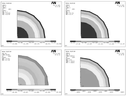
Stress Distribution
any reinforcing bars (plain concrete). Higher axial stress concentration occurs over the center region of the column cross section. This phenomenon describes a correct mechanism of a plain concrete column specimen subjected to axial loading.
Fig. 7. Axial stress distributions over the mid-height cross section of quarter column specimens LC0, LC1, LC2, and LC3
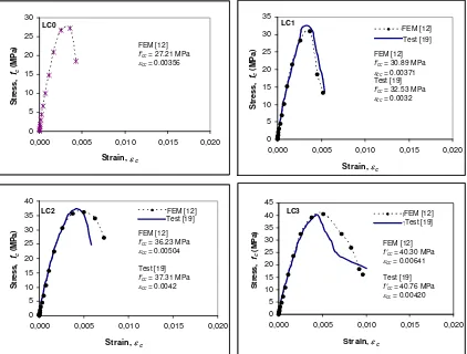
Stress-Strain Relationship
The axial stress-strain curves obtained from the ANSYS solution are confirmed by the experimental results [19]. From the comparisons shown in Fig. 8, it shows that the predictions are in close agreement with the experimental curves. This indicates that the actual behavior of
LC0 LC1
0
0,000 0,005 0,010 0,015 0,020
Strain, εc
0,000 0,005 0,010 0,015 0,020
Strain, εc
0,000 0,005 0,010 0,015 0,020
Strain, εc
0,000 0,005 0,010 0,015 0,020
Strain, εc
column specimens under axial compressive loading can be accurately predicted by the FEM approach.
Fig. 8. Stress-strain curves of column specimens LC0, LC1, LC2, and LC3
Table 3. Comparison between the peak stress and strain at the peak stress obtained from FEM analysis and experimental test
The accuracy of the proposed procedure is also confirmed by the close values of peak stress, strain at the peak stress as well as strain when the stress drops to 85 percent of the peak stress obtained from the FEM analysis and the experimental test. From the comparison values listed in Table 3, it can be seen that the largest differences of all column specimens considered in the study are only 1.011 and 1.306 percents for the peak stress, strain at the peak stress, and strain when the stress drops to 85 percent of the peak stress, respectively.
CONCLUSIONS
Based on the FEM analysis and discussion above, the following conclusions can be drawn:
1. ANSYS software can be used to predict the actual stress-strain relationships of both unconfined and confined reinforced concrete column specimens subjected to axial loading.
2. From the axial stress contours obtained from the FEM analysis, it can be concluded that the axial stress concentrations are in the center regions of the column cross sections, particularly in the confined areas.
REFERENCES
1. Cusson, D.; and Paultre, P., High-Strength Concrete Columns Confined by Rectangular Ties, Journal of Structural Engineering, ASCE, V. 120, No. 3, Mar. 1994, pp. 783-804. 2. Saatcioglu, M.; and Razvi, S., High-Strength Concrete Columns with Square Section
under Concentric Compression, Journal of Structural Engineering, ASCE, V. 124, No. 12, Dec. 1998, pp. 1438-1447.
3. Assa, B.; Nishiyama, M.; and Watanabe, F., New Approach for Modeling Confined Concrete Circular Columns, Journal of Structural Engineering, ASCE, V. 127, No. 7, July 2001, pp. 743-757.
4. Fafitis, A.; and Shah, P. S., Lateral Reinforcement for High-Strength Concrete Columns,
ACI Special Publication, SP-87, Detroit, USA, 1985, pp. 213-232.
5. Nagashima, T.; Sugano, S.; Kimura, H.; and Ichikawa, A., Monotonic Axial Compression Test on Ultra High Strength Concrete Tied Columns, Proceedings of the 10th World
Conference on Earthquake Engineering, Madrid, Spain, July 19-24, 1992, V. 5, pp.
2983-2988.
6. Cusson, D.; and Paultre, P., Stress-Strain Model for Confined High-Strength Concrete,
Journal of Structural Engineering, ASCE, V. 121, No. 3, Mar. 1995, pp. 468-477.
7. Sheikh, S. A.; and Uzumeri, S. M., Analytical Model for Concrete Confinement in Tied Columns, Journal of the Structural Division, ASCE, V. 108, ST12, Dec. 1982, pp. 2703-2722.
8. Sheikh, S. A.; and Uzumeri, S. M., Strength and Ductility of Tied Concrete Columns,
Journal of the Structural Division, ASCE, V. 106, ST5, May 1980, pp. 1079-1102.
10. Nishiyama; M., Fukushima, I.; Watanabe, F.; and Muguruma, H., Axial Loading Test on High-Strength Concrete Prisms Confined by Ordinary and High-Strength Steel, Proc.
Symposium on High-Strength Concrete, 1993, pp. 322-329.
11. Razvi, S.; and Saatcioglu, M., Test of High-Strength Concrete Columns under Concentric Loading, Rep. No. OCEERC 96-03, Ottawa Carleton Earthquake Engineering Research Centre, Ottawa, ON, Canada, 1996, pp. 147.
12. ANSYS, ANSYS User’s Manual Revision 5.6, ANSYS, Inc., Canonsburg, Pennsylvania, 1999, 1286 pp.
13. Santhakumar, R.; Dhanaraj, R.; and Chandrasekaran, E., Behaviour of Retrofitted Reinforced Concrete Beams under Combined Bending and Torsion: A Numerical Study,
Electronic Journal of Structural Engineering, V. 7, 2007, pp. 1-7.
14. Wolanski, A. J., Flexural Behavior of Reinforced and Prestressed Concrete Beams using Finite Element Analysis, MSc. Thesis, Faculty of the Graduate School, Marquette University, Milwaukee, Wisconsin, May 2004, 76 pp.
15. Skinner, J. D., Finite Element Predictions of Plasticity-Induced Fatigue Crack Closure in Three-Dimensional Cracked Geometries, MSc. Thesis, Department of Mechanical Engineering, Mississippi State University, Mississippi State, Mississippi, Aug. 2001, 109 pp.
16. Barbosa, A. F.; and Ribeiro, G. O., Analysis of Reinforced Concrete Structures using ANSYS Nonlinear Concrete Model, Computational Mechanics, CIMNE, Barcelona, Spain, 1998, pp. 1-7.
18. Qi, Z., Finite Element Application to Slab-Column Connections Reinforced with Glass Fibre-Reinforced Polymers, Faculty of Engineering––Memorial University of Newfoundland, Apr. 2004, 52 pp.
19. Hoshikuma, J.; Kawashima, K.; Nagaya, K.; and Taylor, A. W., Stress-Strain Model for Confined Reinforced Concrete in Bridge, Journal of Structural Engineering, ASCE, V. 123, No. 5, May 1997, pp. 624-633.
20. Popovics, S., A Numerical Approach to the Complete Stress-Strain Curve of Concrete,
Cement and Concrete Research, V. 3, No. 5, May 1973, pp. 583-599.
21. Collins, M. P.; Mitchell, D.; and MacGregor, J. G., Structural Design Consideration for High-Strength Concrete, Concrete International, ACI, V. 15, No. 5, May 1993, pp. 27-34.

![Fig. 4. Stress-strain relationship of concrete proposed by Popovics [20,21]](https://thumb-ap.123doks.com/thumbv2/123dok/2298317.1241786/9.612.193.447.72.249/fig-stress-strain-relationship-concrete-proposed-popovics.webp)
![Fig. 5. Stress-strain relationship for reinforcing steel proposed by Park and Paulay [22]](https://thumb-ap.123doks.com/thumbv2/123dok/2298317.1241786/10.612.171.454.69.251/stress-strain-relationship-reinforcing-steel-proposed-park-paulay.webp)