arXiv:1711.05154v1 [eess.SP] 14 Nov 2017
Robust massive MIMO Equilization for mmWave
systems with low resolution ADCs
Kilian Roth
∗†, Josef A. Nossek
†‡∗ Next Generation and Standards, Intel Deutschland GmbH, Neubiberg, Germany
Email:{kilian.roth}@intel.com
† Department of Electrical and Computer Engineering, Technical University Munich, Munich, Germany
Email:{kilian.roth, josef.a.nossek}@tum.de
‡ Department of Teleinformatics Engineering, Federal University of Ceara, Fortaleza, Brazil
Abstract—Leveraging the available millimeter wave spectrum will be important for 5G. In this work, we investigate the performance of digital beamforming with low resolution ADCs based on link level simulations including channel estimation, MIMO equalization and channel decoding. We consider the recently agreed 3GPP NR type 1 OFDM reference signals. The comparison shows sequential DCD outperforms MMSE-based MIMO equalization both in terms of detection performance and complexity. We also show that the DCD based algorithm is more robust to channel estimation errors. In contrast to the common believe we also show that the complexity of MMSE equalization for a massive MIMO system is not dominated by the matrix inversion but by the computation of the Gram matrix.
Index Terms—MIMO equalization, low resolution ADC, mil-limeter wave, wireless communication.
I. INTRODUCTION
For future millimeter Wave (mmWave) mobile broadband systems, analog/hybrid beamforming are considered to be a possible solution to the excessive power consumption at the receiver. Due to the large bandwidth, high resolution Analog-to-Digital-Converters (ADCs) have a significant amount of power. Therefore, they are considered to be a major contributor to the power consumption of a mmWave receiver.
Analog/hybrid beamforming highly depend on the optimal alignment of beams. The required beam-training/alignment has to be implemented as a search procedure, essentially different configuration are tested and the best one is selected [1]. Con-sidering such a procedure for multiple UEs at the same time can be considered to have a large overhead. A possible solution to these type of systems is digital beamforming with low resolution ADCs. As we showed in [2] the power consumption of the receiver frontend of both systems is comparable. In most cases the low resolution ADC digital beamforming is most energy efficient. A lot of the work on low resolution ADC digital beamforming only considers the extreme case of 1-bit quantization for the inphase and quadrature [3], [4], [5]. As we showed in [2] it is not clear that 1-bit quantization does lead to the most energy efficient implementation, we consider low resolution ADCs in general.
Many of the investigated channel estimation and detection schemes require detailed knowledge about the structure of the channel. For example algorithms like GAMP [3], [4] are very sensitive to the case that their modeling assumptions are not
fully valid. Other algorithms like Expectation Maximization (EM) require accurate knowledge about the sparsity or related parameters [3], [4]. In a practical system, this knowledge is hard to obtain. In addition, the systems should robust regarding cases, where the assumptions leading to a specific algorithm are not fully satisfied.
Many massive Multiple Input Multiple Output (MIMO) equalization schemes consider only perfect channel estimation [6], [7] even without channel coding. We think the propagation of the channel estimation error inside the Multi User - Mul-tiple Input MulMul-tiple Output (MU-MIMO) equalization is not straight forward. Only for linear methods the influence of the channel estimation error can be investigated theoretically [8]. This motivated us to investigate channel estimation, MIMO equalization in combination with channel coding and low resolution ADCs.
Therefore, we wanted to investigate the performance of these systems without limiting assumptions on the statistics of the channel. We also wanted to put the focus on linear, low complexity algorithms while considering reference signals developed for NR in 3GPP. Even so we do not consider finite resolution calculation in this work, it is important to mention that massive MIMO is very robust to these effects [9]. This could further simplify the required calculation and lead to an implementation that might even be feasible for mobile devices. In the following sections, we introduce the used channel estimation scheme including a description of the recently in 3GPP agreed NR Type 1 OFDM reference signals. Afterwards, we introduce the sequential Dichotomous Coordinate Descent (DCD) algorithm for MU-MIMO equalization. In the end, we show a performance and computational complexity based comparison to Minimum Mean Square Error (MMSE) MU-MIMO detection.
II. SYSTEMMODEL A. NR reference structure
As described in [10], the Orthogonal Frequency Domain Multiplexing (OFDM) type 1 DeModulation Reference Signals (DMRS) consists of a Pseudo Noise (PN) sequence defined by parts of a length-31 Gold sequence. There are three techniques used to orthogonalize the reference signal for different users:
DMRS OFDM symbols subcarriers
OFDM symbols DMRS REs
Fig. 1. 3GPP NR OFDM type 1 DMRS for up to 8 users.
• Frequency Division Multiplex (FDM)
• Code Division Multiplex (CDM) for the case of more than 4 users
The resource grid in Fig. 1 shows a possible allocation of the reference symbol Resource Elements (REs) within a slot. Among the three ways to orthogonalize the reference signals send by different users or for different MIMO streams, FDM and CDM are most commonly used in many communication systems. CS is not encountered in many current wireless communication standards except for Long Term Evolution (LTE) Uplink (UL), thus more detailed explanation on how it could provide sufficient orthogonality is needed.
Since a CS of half of the OFDM symbol offers the highest distance between two reference sequences used for different users, only this value is foreseen in the standard. Due to the properties of the Fourier transformation, a cyclic shift of N/2 in the time domain corresponds to a modula-tion of the frequency domain sequence with the sequence
c = [−1,1,−1,1,· · ·]T. The reference symbol sequence s
is generated as QPSK symbols with the bits defined by a PN sequence. In this case one user sends the sequence s
and the other the time domain cyclic shifted version s⊙c. Assuming perfect synchronization and the delay spread of the channel being smaller than the Cyclic Prefix (CP), the linear convolution with the channel is converted to a circular one.
To demodulate the DMRS, we first transform the signal into the frequency domain. Afterwards, we multiply with the complex conjugate of the of the used reference sequence. Since this would correspond to a cyclic convolution in the time domain this does still include all possible cyclic shifts and therefore also the one from the cyclic shifted sequence. Thus, additionally we need to apply a windowing in the time domain to limit the interference among the original sequence and its cyclic shift. The windowing in the time corresponds to a cyclic convolution in the frequency domain. It will be implemented by the spatial smoothing filters shown in the following channel subsection. Combining this observations with the fact that s
should be designed to have a cyclic auto-correlation function with only one strong peak and only small values otherwise, we can conclude that a cyclic shift can sufficiently orthogonalize
TABLE I
CONFIGURATION OFNRTYPE1 OFDMREFERENCE SIGNALS.
MIMO layeri [wiCS(0), wiCS(1)] wFDMi [wiCDM(0), wiCDM(1)] 1 [1, 1] 0 [1, 1]
2 [1,−1] 0 [1, 1] 3 [1, 1] 1 [1, 1] 4 [1,−1] 1 [1, 1] 5 [1, 1] 0 [1,−1] 6 [1,−1] 0 [1,−1] 7 [1, 1] 1 [1,−1] 8 [1,−1] 1 [1,−1]
the signal from different users.
In general we can describe the reference signal ofith MIMO layerri on sub-carrier kand OFDM symbolℓ as
ai(k,ℓ)=αCS(i, k)αFDM(i, k)αCDM(i, ℓ)[s]⌊k/2⌋, (1)
whereαCS(i, k),αFDM(i, k)andαCDM(i, ℓ)are the changes of sequence based on CDM, FDM and CS. These parameters are defined in the following way
αCS(i, k) =wiCS(⌊k/2⌋mod 2),
αFDM(i, k) =
1, kmod 2 =wi
FDM
0, otherwise
,
αCDM(i, ℓ) =
wCDMi (0), ℓ=ℓ0
wi
CDM(1), ℓ=ℓ0+ 1
,
(2)
whereℓ0 is the first DMRS symbol with DMRS in a slot. A
table of the parameters wi
CS, wiFDM and wCDMi dependent on the MIMO layeri can be found in Table I. It is important to mention that for the case of 1 to 4 MIMO layers, no CDM based orthogonalization is necessary,
B. Channel Estimation
Assuming perfect synchronization of the timing and carrier frequency, the OFDM receive signal Yk,ℓ of subcarrierk and
OFDM symbolℓcan be written as
Yk,ℓ,=Hk,ℓXk,ℓ+ηk,ℓ, (3)
where we assume that the Channel Impulse Response (CIR) is shorter than the CP, andHk,ℓ,Xk,ℓ andηk,ℓ are the channel,
note that this technique assumes knowledge of the following statistical channel parameters:
• Doppler spread
• Delay spread
• Receive Signal to Noise Ratio (SNR) of each user
As we consider a MU-MIMO scenario, we need to ensure that different users have orthogonal reference sequences. In particular, we will assume that the training sequences are orthogonal. As we showed in the previous subsection, this can be ensured by the chosen design. Therefore, the following calculation is done for each user, and thus no user index is included to simplify the notation.
Assuming a reference symbol is present on subcarrier q
and symbol time p, we multiply the signal with the known reference signal to obtain the corresponding channel estimate for this symbol
ˆ
Hp,q=Yp,qXp,q∗ =Hp,q+ηp,q, (4)
where we assume thatXp,q∗
= 1. By combining the channel estimates for all resource elements on K subcarriers and L
symbols we get
ˆ
hr=
h ˆ
H1,1,Hˆ2,1,· · · ,HˆK−1,L,HˆK,L
iT
. (5)
For all positions where no reference signals were sent, the corresponding element ofhˆris set to zero. The setPcontains
the indices of the reference symbols inhˆr.
Applying the matrices for interpolation and smoothing in timeAtand frequencyAfdomain, we get the overall estimate
of the channel at each position ˆ
h=Atfhˆr= (At⊗Af) ˆhr. (6)
We choose these interpolation matrices separately for each dimension separately to reduce the complexity. In general to achieve the theoretical optimal performance, these interpola-tion matrices have to be chosen according to the covariance matrix of the channel, which might not be separable. As shown in [11] for the time-frequency case this leads to a minimal performance loss, but with significantly lower complexity. In many cases the covariance is unknown, and one would need to generate the interpolation martrices based on some model for the covariance, whose parameters would also then have to be estimated. It is important to mention that the same interpolation matrixAf is used for all OFDM symbols
containing reference symbols. This means that if the reference signal pattern in these symbols is not the same, we need to apply different matrices for each symbol. But fortunately this assumption holds true for the chosen 3GPP NR OFDM type 1 DMRS.
For the example in this work we assume the channel remains constant in one subframe of 14 OFDM symbols (Doppler spread equal to zero). Therefore, the time interpolation matrix
At consists only of a averaging among the OFDM symbols
that contain reference symbols.
The frequency interpolation and smoothing matrix Af is
based on the MMSE solution described in [11]. To generate
these matrices based on this method, we need to generate the auto and cross correlation of the channelRhdhd andRhdhℓ.
The symbols hd and hℓ are the vector of the channel at
the position of the reference signals and the channel on all subcarriers on OFDM symbolℓ. In the case that we know all these matrices, the interpolation matrix is defined as
Af =Rhdhℓ(Rhdhd+Rηη)−1, (7)
where Rηη is the noise covariance matrix. In a practical
system we could easily have hundreds of subcarriers, thus the complexity of the matrix inversion is extreme. Even if the values of the inversion are precomputed the following matrix vector multiplication also has a high complexity. We therefore limit the length of reference symbols considered for the interpolation to KC. This does decrease the complexity
and has only a minor impact on the performance, since the channel that have a large distance in terms of subcarriers are close to uncorrelated.
In addition for a practical system is in many cases not pos-sible to directly observe and estimate the covariance matrix of the channel, especially at the position with no reference signals present. Consequently, we use a model for the generation of the covariance matrices. For many real world scenarios the channel path arriving later at the receiver propagate through a longer path, thus leading to lower energy at the receiver. This can be well approximated by a exponential Power Delay Profile (PDP).
Since all the elements of Rhdhℓ and Rhdhd represent the
cross correlation of different elements of the channel. Thus, all elements of these matrices are defined by the cross correlation between the channels on subcarrieriandj
E[hih∗j] =
1
1−j2πτRMS∆fd(i, j)
, (8)
whereτRMS is the Root Mean Square (RMS) delay spread and
d(i, j)the distance of theith to the jth subcarrier.
III. MIMO DETECTIONALGORITHM
In this section we show how the sequential DCD with bound is derived from a relaxation of the Most Likelyhood (ML) MIMO equalization. The classical problem of ML detection can be formulated as
ˆ
x= argmin
xn∈X
||y−Hx||22, (9) where Xis the set containing all possible transmit symbols. The symbolsx,H,yandxˆ represent the transmit symbol, the channel, the receive symbol and the symbol after the detection of the system. The complexity of this discrete optimization problem grows exponentially with the dimensions ofxand the size of the setX. Thus, for higher number of spatial streams as envisioned for massive MIMO it is not feasible to solve this problem.
Fortunately, as the number of receive antennas grows large with respects the number of simultaneously served users, the MMSE solution to the relaxed optimization problem
ˆ
Algorithm 1 Sequential DCD with bound
Require: A,b,N,H,B,Nu,Mb
Initialization: x←0,r←b,α←H,m←0,
UpdateFlag← false,k←0
while m < Mb do
forn∈ {1,· · ·, N} do if α/2[A]n,n <|[r]n| then
t←[x]n+sign([r]n)α ift≤B then
[x]n←t
r←r−sign([r]n)αan
UpdateFlag←true,k←k+ 1
end if end if end for ifk≥Nu then
returnx,r
end if
ifUpdateFlagthen
UpdateFlag←false
else
m←m+ 1,α←α/2
end if end while return x,r
approaches the performance of the ML detection [12]. Un-fortunately, the close form solution to this problem requires knowledge about the noise covariance matrix. For a system with a large number of antennas this is hard to attain.
Therefore, we choose to relax the ML detection problem in a ways that reduces the complexity, but not making any assumptions on the noise statistics
ˆ
x= argmin
ℜ(xn)∈[−B,B],ℑ(xn)∈[−B,B]
||y−Hx||22. (11) The variable B forces the real and imaginary part of each element of the vector xˆ to be in the range from −B to B. In the following paragraphs we will show how to solve this optimization problem efficiently and that we do not need to make any assumption on the noise statistics.
This problem can be reformulated into solving the following linear system of equations
HHHx=HHy. (12) Thus, we can utilize a coordinate descend based method to solve this problem. To reduce the complexity we selected the step-size to be of the form 2−l, where l is an integer. This
has the advantage that all multiplications with this number can be implemented as bit shifts. These algorithms are called DCD as described in [13], [14] for multi user detection in a Code Division Multiple Access (CDMA) system and is shown in Algorithm 1. The parameters H, B, Nu and Mb are the
maximum step-size, the upper bound of detected symbols, the maximum number of updates and the maximum number of
step-size divisions by 2 of the algorithm. The parameter B
should be chosen in a way to just accommodate the Quadrature Amplitude Modulation (QAM) constellation in the scaling before the data detection. For the case that the constellation is not bounded this parameters can be set to a reasonable large value or even infinity. A DFT-spread-OFDM (DFT-s-OFDM) system is a example for a constellation that is not bounded when the data detection is calculated in the frequency domain. The value of H should be of the form 2−l, where l is an
integer. Since it is not useful to start with a step-size that is larger than the final bound, H should also be smaller than
B. A good way to chooseH would beH = 2⌊log2(B)⌋. This
ensures that we start with the maximum possible step-size to enable fast convergence. The symbolsA,bandN define the linear systems of equations
Ax=b, (13) and the size of the vector b. The vectors x andr represent the resulting vector and the residual error, which is updated in every step. Since algorithm 1 solves only real linear systems of equationsAandbare related toH andyin the following way
A=
ℜ(HHH) −ℑ(HHH)
ℑ(HHH) ℜ(HHH)
,b=
ℜ(HHy)
ℑ(HHy)
. (14)
Since we solve the equivalent real linear system of equations the value ofN is double the number of users/spatial streams to be detected. The resulting value of x is also going to be split between real and imaginary part in the same way as b. A simple recombination ofxleads to detected symbol.
IV. SIMULATIONRESULTS
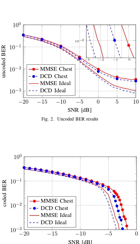
In this section we compare the performance of sequential DCD to MMSE equalization. Since we consider system with low resolution ADCs and channel estimation error, the noise is in general not white. We also tested additional noise whitening for both system, but since no performance gain was observed at an addition computational cost, we only show results without noise whitening. The simulation parameter in Table II shows the most important simulation parameters. It is also important to mention that the bounds for the sequential DCD equalization tightly encloses the QAM constellation.
A. Performance Results
The uncoded and coded Bit Error Rate (BER) results are shown in Fig. 2 and 3. Due to the frequency selective channel and the 2-bit resolution ADCs, the uncoded BER does exhibits a error floor. It is also obvious that error floor of the DCD is lower then the one of the MMSE algorithm w/o ideal channel estimation. As we can see from the zoomed in part around 10−2 BER, the performance of DCD is slightly more robust
TABLE II
SIMULATIONPARAMETERS.
Parameter Value
Reference Signal 3GPP NR OFDM type 1 DMRS Channel Estimation 2x1D MMSE and ideal Number of Users 8
Number of receive antennas 64
Channel model Exponential PDP (no Doppler spreach)
SNR definition Average per user per antenna SNR Channel code LTE turbo code with rate 0.9 MIMO detection algorithms MMSE and DCD-Bound
ADC resolution 2 bit Modulation format 16 QAM
−20 −15 −10 −5 0 5 10
10−3
10−2
10−1
100
SNR [dB]
u
n
co
d
ed
B
E
R
MMSE Chest DCD Chest MMSE Ideal DCD Ideal
−3 −2 −1 0 10−2
Fig. 2. Uncoded BER results
−20 −15 −10 −5 0
10−3
10−2
10−1
100
SNR [dB]
co
d
ed
B
E
R
MMSE Chest DCD Chest MMSE Ideal DCD Ideal
Fig. 3. Coded BER with LTE turbo code rate = 0.9.
10000 1500 2000 2500 3000
2 4 6 ·10
4
Fig. 4. Histogram of the additions require to converge.
TABLE III
COMPLEXITY PER OPERATION.
operation real addi-tions
real multi-plications
logic op-erations
HH
H 8128 8192 19038400
hH
y 2032 2048 5521600
HH
H+I 16 0 2000
(HHH+I)−1 1700 1900 4392500
(HH
H+I)−1hHy 240 256 593200
Sequential DCD with bound
2000 0 250000
B. Computational Complexity Results
Since the DCD algorithm has no multiplications we need to compare the complexity to MMSE by mapping additions and multiplications to logic operations. The work in [15], [16] offer a mapping of real additions and multiplications to logic gates. Assuming 18 bit signed fixed point calculation an addition and a multiplication can be implemented using 125 and 2200 NAND gates with two inputs, respectively. To compare the different algorithms, we compare this number of logic gates as the number of logic operation required to calculate the result. As the sequential DCD algorithm is an iterative procedure we need to investigate the converges of it. The histogram in Fig. 4 shows the number of addition used to process one symbol vector for the simulation parameters presented in the preceding paragraph. The comparisons are implemented as a subtraction followed by checking if the sign bit is set or not. Therefore, they are counted to have equal complexity compared to an addition. The number of comparisons is low compared to additions used for updating the residual vectorr. The average complexity is 1972 real additions. For simplicity we use 2000 for the following analysis.
From the Table III it is easy to see that even just the
TABLE IV
COMPLEXITY RESULTS.
detection algorithm scenario 1 scenario 2
MMSE 29547700 109040100
multiplication with the already inverted matrix is more com-plex the solving the linear system of equations with the Sequential DCD algorithm with bound. It is also obvious that the complexity is dominated by the computation of the Gram matrix (HHH). It is important to mention that for
the calculation of the Gram matrix, we already exploited the symmetry of the resulting matrix to minimize the necessary multiplications and additions. All other computation steps have a much lower complexity. In this investigation, we neglected the necessary complexity for normalization of the signal power and the additional complexity for making the MMSE equalizer unbiased.
To Compare the MMSE equalizer to the algorithm devel-oped here, we compare two scenarios. In the first scenario, the matrix computed to generate the MMSE result is calculated separately for each sub-carrier (scenario 1). In the second case we assume that the matrix can be reused to detect the symbol in 14 consecutive OFDM symbols on the same sub-carrier (scenario 2). There are few common operations to both systems and we assume that this intermediate calculations can be stored and reused for scenario 2. The complexity for both algorithms are shown in Table IV. The overall computational complexity of our approach compared to MMSE is reduced while at the same time the performance is improved. In the first scenario the improvement is about 16% in the second it is in the range of 10%.
V. CONCLUSION
Our investigation showed that a bounded DCD MIMO equalization algorithm does outperform a MMSE based equal-ization. In addition, sequential DCD has a lower computational complexity. But it is important to mention that in contrast to many other papers considering the complexity for massive MIMO we showed that the complexity is dominated by the computation of the gram matrix and not the matrix inversion. This evaluation shows that it is possible to achieve high data rates with digital beamforming mmWave system with low resolution ADCs by considering low complexity algorithms.
ACKNOWLEDGMENT
This work has been performed in the framework of the Hori-zon 2020 project ONE5G (ICT-760809) receiving funds from the European Union. The authors would like to acknowledge the contributions of their colleagues in the project, although the views expressed in this contribution are those of the authors and do not necessarily represent the project.
REFERENCES
[1] IEEE Standard for Information technology–Telecommunications and information exchange between systems–Local and metropolitan area networks–Specific requirements-Part 11: Wireless LAN Medium Access Control (MAC) and Physical Layer (PHY) Specifications Amendment 3: Enhancements for Very High Throughput in the 60 GHz Band, Std., Dec 2012.
[2] K. Roth and J. A. Nossek, “Achievable rate and energy efficiency of hybrid and digital beamforming receivers with low resolution ADC,”
IEEE Journal of Selected Areas in Communications (IEEE JSAC) Special Issue on Millimeter Wave Communications for Future Mobile Networks (JSACMillimeterWave’2017), 2017.
[3] J. Mo et al., “Channel estimation in millimeter wave MIMO systems with one-bit quantization,” inAsilomar Conf. on Signals, Systems and Computers 2014, Pacific Grove, CA, USA, Nov. 2014, pp. 957–961. [4] J. Choi, J. Mo, and R. W. Heath, “Near maximum-likelihood detector
and channel estimator for uplink multiuser massive mimo systems with one-bit adcs,”IEEE Transactions on Communications, vol. 64, no. 5, pp. 2005–2018, May 2016.
[5] Y. Li et al., “Channel estimation and performance analysis of one-bit massive mimo systems,”IEEE Transactions on Signal Processing, vol. 65, no. 15, pp. 4075–4089, Aug 2017.
[6] X. Gao, L. Dai, Y. Hu, Z. Wang, and Z. Wang, “Matrix inversion-less signal detection using sor method for uplink large-scale mimo systems,” in2014 IEEE Global Communications Conference, Dec 2014, pp. 3291– 3295.
[7] M. Wu, C. Dick, J. R. Cavallaro, and C. Studer, “High-throughput data detection for massive mu-mimo-ofdm using coordinate descent,”IEEE Transactions on Circuits and Systems I: Regular Papers, vol. 63, no. 12, pp. 2357–2367, Dec 2016.
[8] E. Eraslan, B. Daneshrad, and C. Y. Lou, “Performance indicator for mimo mmse receivers in the presence of channel estimation error,”IEEE Wireless Communications Letters, vol. 2, no. 2, pp. 211–214, April 2013. [9] S. Gunnarsson et al., “Lousy processing increases energy efficiency in massive MIMO systems,” in European Conference on Networks and Communications (EuCNC) 2017, Oulu, Finland, June 2017, pp. 1–5. [10] 3GPP, “NR; Physical channels and modulation,” 3rd Generation
Partnership Project (3GPP), TS 38.211, 2017. [Online]. Available: http://www.3gpp.org/ftp/Specs/html-info/38211.htm
[11] P. Hoeher, S. Kaiser and P. Robertson, “Two-dimensional pilot-symbol-aided channel estimation by Wiener filtering,” inInt. Conf. on Acoustics, Speech, and Signal Processing (ICASSP) 1997., vol. 3, Munich, Bavaria, Germany, Apr. 1997, pp. 1845–1848 vol.3.
[12] S. Yang and L. Hanzo, “Fifty years of mimo detection: The road to large-scale mimos,”IEEE Communications Surveys Tutorials, vol. 17, no. 4, pp. 1941–1988, Fourthquarter 2015.
[13] Z. Quan, J. Liu, and Y. Zakharov, “Fpga implementation of dcd based cdma multiuser detector,” in 2007 15th International Conference on Digital Signal Processing, July 2007, pp. 319–322.
[14] ——, “Fpga design of box-constrained mimo detector,” inInt. Conf. on Communications (ICC) 2009, Dresden, Germany, June 2009, pp. 1–5. [15] V. K. Kodavalla. Ip gate count estimation
methodology during micro-architecture phase. [Online]. Available: https://www.design-reuse.com/articles/19171/ip-gate-count-estimation-micro-architecture-phase.html