means, electronic or mechanical, including photocopying, recording, or by any information storage or retrieval system without written permission from Course PTR, except for the inclusion of brief quotations in a review.
The Premier Press logo and related trade dress are trademarks of Premier Press and may not be used without written permission.
DirectX is a registered trademark of Microsoft Corporation in the U.S. and/or other countries.
© Microsoft Corporation, 2002. All rights reserved.
All other trademarks are the property of their respective owners.
Important: Course PTR cannot provide software support. Please contact the appropriate software manufacturer’s technical support line or Web site for assistance.
Course PTR and the author have attempted throughout this book to distin-guish proprietary trademarks from descriptive terms by following the capital-ization style used by the manufacturer.
Information contained in this book has been obtained by Course PTR from sources believed to be reliable. However, because of the possibility of human or mechanical error by our sources, Course PTR, or others, the Publisher does not guarantee the accuracy, adequacy, or completeness of any information and is not responsible for any errors or omissions or the results obtained from use of such information. Readers should be particularly aware of the fact that the Internet is an ever-changing entity. Some facts may have changed since this book went to press.
Educational facilities, companies, and organizations interested in multiple copies or licensing of this book should contact the publisher for quantity dis-count information. Training manuals, CD-ROMs, and portions of this book are also available individually or can be tailored for specific needs.
ISBN: 1-59200-349-4
Library of Congress Catalog Card Number: 2004090736 Printed in the United States of America
04 05 06 07 08 BH 10 9 8 7 6 5 4 3 2 1
Course PTR, a division of Course Technology 25 Thomson Place
Manager of Editorial Services:
To my children,
Virginia, Elizabeth, and Ian
Acknowledgments
I
’d definitely like to thank Emi Smith and Karen Gill for working so patiently with me in the writing of this book. I’m very grateful to Joseph Hall for agreeing to do the technical editing. His comments regarding the code samples kept me sane.I’d also like to thank Course PTR for giving me the opportunity to present such a won-derful topic as DirectX.
Finally, I’d like to send a heartfelt thank you to Albert James, my friend and mentor, who helped me embrace my love for programming and allow it to grow.
About the Author
WENDY JONES devoted herself to computers the first time her eyes befell an Apple IIe in
elementary school. From that point on, she spent every free moment learning BASIC and graphics programming, sketching out her ideas on graph paper to type in later. Other computer languages followed, including Pascal, C, Java, and C++.
As Wendy’s career in computers took off, she branched out from DOS, teaching herself Windows programming and then jumping into the dot-com world for a bit. Although Internet companies provided cash, they didn’t provide fulfillment, so Wendy started expanding her programming skills to games, devoting any extra energy to its pursuit.
Wendy’s true passion became apparent when she got the opportunity to work for Atari’s Humongous Entertainment as a game programmer. During her time at Atari, she worked on both PC and console titles, thrilled with the challenge they provided.
Wendy is currently working with PocketPC software and handheld gaming devices.
If you have any comments or questions about this book, you can reach Wendy at [email protected].
Contents at a Glance
Introduction . . . .xv
Part I
Getting Down the Basics . . . .1
Chapter 1 The What, Why, and How of DirectX . . . .3
Chapter 2 Your First DirectX Program . . . .9
Chapter 3 Surfaces, Sprites, and Salmon . . . .35
Part II
It’s a 3D World After All . . . .63
Chapter 4 3D Primer . . . .65
Chapter 5 Matrices, Transforms, and Rotations . . . .87
Chapter 6 Vertex Colors, Texture Mapping, and 3D Lighting . . . .117
Chapter 7 Meshes . . . .147
Chapter 8 Point Sprites, Particles, and Pyrotechnics . . . .177
vii Contents at a Glance
Part III
Additional Needs . . . .199
Chapter 9 Using DirectInput . . . .201
Chapter 10 DirectSound . . . .237
Chapter 11 The Final Project . . . .257
Part IV
Appendixes . . . .293
Appendix A Answers to End-of-Chapter Exercises . . . .295
Appendix B Using the CD-ROM . . . .311
Glossary . . . .315
Contents
Introduction . . . .xv
Part I
Getting Down the Basics . . . .1
Chapter 1 The What, Why, and How of DirectX . . . .3
Chapter 2 Your First DirectX Program . . . .9
What Is DirectX? . . . .3
The Components . . . .4
Why Is DirectX Needed? . . . .4
How Is DirectX Put Together? . . . .5
The Component Object Model . . . .6
The Architecture . . . .6
Chapter Summary . . . .7
Creating the Project . . . .9
Adding the Windows Code . . . .11
WinMain . . . .12
InitWindow . . . .13
WndProc . . . .14
Time for DirectX . . . .16
The Direct3D Object . . . .16
Creating the Rendering Device . . . .17
Clearing the Screen . . . .19
Displaying the Scene . . . .20
xi
Vertex Colors, Texture Mapping, and 3D Lighting . . . .117
Coding the Demo . . . .266
The Game Application Class . . . .266
Creating the Game Timer . . . .267
Hooking the Game Application into WinMain . . . .268
Adding Objects to the World . . . .270
The CGameObject Class . . . .271
The CModel Class . . . .272
The Game Object List . . . .276
Creating the Planet . . . .277
The CPlanet Class . . . .277
Adding the Planet to the Scene . . . .280
Adding a Spaceship . . . .281
Moving in the Universe . . . .283
The Spaceship Move Function . . . .283
Bringing in DirectInput . . . .285
Releasing Your Creation to the World . . . .288
Packaging Your Game for Release . . . .288
What Tools Are Available to Bundle My Game? . . . .289
The DirectX Runtime . . . .289
Shipping the DirectX Runtime with Your Game . . . .289
Installing the DirectX Runtime . . . .290
Chapter Summary . . . .292
Part IV
Appendixes . . . .293
Appendix A Answers to End-of-Chapter Exercises . . . .295
. . . .311
Appendix B Using the CD-ROM What’s on the CD-ROM . . . .311
Installing the DirectX SDK . . . .311
Glossary . . . .315
Introduction
G
ame programming is an exciting job in the computing world. Where else do you get the chance to create virtual worlds that encompass creatures or places nor-mally found only in dreams? You give people the ability to become anyone they want, and provide them with environments that bring their fantasies to life.The game industry is growing by leaps and bounds, and the technology is expanding right along with it. Just a few years ago, video cards with 3D hardware on the consumer level were unheard of. Only expensive SGI workstations were capable of real-time 3D, and OpenGL were in its infancy. As PCs became more popular, OpenGL was ported to this expanding platform, bringing 3D rendering to the masses for the first time.
Windows was still an unpopular platform for games, but that began to change when Microsoft introduced DirectX. DirectX slowly gained popularity until it surpassed OpenGL as the standard way to create 3D graphics under Windows. Today, most PC games on the market are built on DirectX, enabling gamers to experience the latest graph-ics technologies and the most realistic worlds.
How Much Should You Know?
A relatively decent understanding of C++ and object-oriented concepts can help you understand all the lessons presented in this book. Basic math skills are a plus, although most math concepts are explained in detail. Working knowledge of Visual Studio .NET 2003 or any product in the Visual Studio family is helpful. The opening chapters explain what you need to get started.
How to Use This Book
This book is divided into three parts. The first part describes DirectX and how to get your first DirectX program up and running. The second part gives you the basics you need for designing and building 3D worlds, with an introduction to 3D concepts and Direct3D. The third and final part rounds out your DirectX knowledge with an introduction to sound processing with DirectSound and getting input from the user with DirectInput. The book wraps up everything with a final project that shows you how to apply the con-cepts you’ve learned.
Getting Down
the Basics
Chapter 1
The What, Why, and How of DirectX . . . .3
Chapter 2
Your First DirectX Program . . . .9
Chapter 3
Surfaces, Sprites, and Salmon . . . .35
chapter 1
The What, Why,
and How of DirectX
D
irectX is the premier game Application Programming Interface (API) for theWindows platform. Just a few years ago, game makers were struggling with problems stemming from hardware incompatibilities, making it impossible for everyone to enjoy their games. Then Microsoft came along with DirectX. It provided game makers with a single, clean API to write to that would almost guarantee compati-bility across different sets of PC hardware. Over the years since DirectX’s release, the num-ber of games that are running under Windows has increased dramatically.
Here’s what you’ll learn in this chapter:
■ What DirectX is
■ Why DirectX is useful
■ Which components make up the DirectX API
What Is DirectX?
DirectX is the Microsoft collection of APIs that are designed to give game developers a low-level interface to the PC hardware that is running Windows. Currently on version 9.0, each DirectX API component provides access to different aspects of the hardware, includ-ing graphics, sound, and networkinclud-ing, all through a standard interface. This interface allows developers to write their games using one set of functions, regardless of the hard-ware they’re being run on.
The Components
The DirectX API is split into multiple components, each one representing a different aspect of the system. Each API can be used independently, thereby adding only the func-tionality that your game requires. Here are the components:
■ DirectX Graphics. This is the component that handles all graphics output. This API provides functions for handling 2D and 3D graphics drawing, as well as initializing and setting the resolution for your game.
■ DirectInput. All user input is handled through this API. This component includes support for devices such as the keyboard, mouse, gamepad, and joysticks.
DirectInput also now adds support for force-feedback.
■ DirectPlay. Network support for your games is added through DirectPlay. The
networking functions provide communication with other machines, allowing more than one person to play. DirectPlay gives you a high-level interface for networking, keeping you from having to implement every aspect of network communication.
■ DirectSound. When you need to add sound effects or background music, this is the API to use. DirectSound’s functionality allows for the loading and playing of one or more WAV files, while providing complete control over how they’re played.
■ DirectMusic. This component allows you to create a dynamic soundtrack. Sounds
can be played back on a timed schedule or adapted to the gameplay using pitch, tempo, or volume changes.
■ DirectShow. You access cut scenes and streaming audio through this component. AVI, MP3, MPEG, and ASF files are just a few of the formats that DirectShow allows to be played. With DirectShow, the entire file doesn’t have to be loaded into memory; you can stream the file from the hard drive or CD-ROM.
■ DirectSetup. After your game is complete, you’ll want to show it to others. DirectSetup gives you the functionality to install the latest version of DirectX on the user’s computer.
n o t e
The DirectX Graphics component includes all the functionality of both DirectDraw and Direct3D. Version 7 of DirectX was the last version to separate DirectDraw into its own interface.
Why Is DirectX Needed?
5 How Is DirectX Put Together?
between their application code and the hardware it was running on. This had both advan-tages and problems. For example, because there was a direct path between the game code and the hardware, developers could pull every ounce of power out of the machine, giving them complete control over how their games performed. The downside to this included the need to write device drivers themselves for any hardware they wanted their game titles to support. This even included common hardware, such as video and sound cards.
At the time, not all video cards followed the same standard. This made drawing to the screen difficult if you wanted to support a resolution above 320 ×240. Just writing a game
using 640 ×480 resolution caused developers to write directly to video memory and
han-dle the manipulation of video registers themselves. Developers were definitely looking for a better and easier way.
When Windows 3.1 was released, it carried with it the same limitations that DOS had. Because Windows ran on top of DOS, it severely limited the resources available to games and took away the direct access that developers had enjoyed for so long. Most games that were written to support Windows at the time consisted mainly of card games and board games, whereas action games continued to support only DOS.
Previously, Microsoft had attempted to give developers a faster way to access the video adapter through a library called WinG. It predated DirectX and offered only a few func-tions. WinG was a nice attempt, but it still didn’t give developers the much-needed access to the system they enjoyed under DOS.
Microsoft did address a lot of these issues with the release of DirectX 1, called the Game Software Development Kit (SDK). DirectX 1 gave developers a single library to write to, placing a common layer between their games and the PC hardware. Drawing graphics to the screen became easier. The first version of DirectX still didn’t give support for all the hardware out there, but it was a great starting point in giving game developers what they had been waiting for. Over the years, there have been nine releases of DirectX, each one improving and adding support for new technologies such as network play, streaming audio and video, and new kinds of input devices.
How Is DirectX Put Together?
DirectX made life a bit easier for developers who wanted to write games under Windows. Developers had a clear set of libraries and support from Microsoft, who had finally real-ized the importance and market potential of games.
The Component Object Model
The DirectX API is based on the Component Object Model (COM). COM objects consist of a collection of interfaces that expose methods that developers use to access DirectX. COM objects are normally DLL files that have been registered with the system. For DirectX COM objects, this happens during the installation of DirectX. Although they’re similar to C++ objects, COM objects require the use of an interface to access the methods within them. This is actually an advantage over standard objects because multiple versions of an interface can be present within a COM object, allowing for backward compatibility.
For instance, each version of DirectX includes a new DirectDraw interface that is accessi-ble through the API, while still containing the previous version so it doesn’t break exist-ing code. Games that were created usexist-ing DirectX 7 can work with DirectX 9 with no problems.
An additional advantage to COM objects is their ability to work with multiple languages beyond just C++. Developers can use Visual Basic, C++, or C# and still use the same DirectX libraries.
The Architecture
DirectX is based on two layers: the API layer and the Hardware Abstraction Layer (HAL). The API layer communicates with the hardware in the machine by talking to the HAL. The HAL provides a standardized interface to DirectX, while also being able to talk directly to the hardware through its specific device driver. Because the HAL needs to know how the hardware and device driver actually work, the hardware manufacturer writes it. You never interact with the HAL directly while writing your game, but you do access it indirectly through functions that DirectX provides. Figure 1.1 displays how the HAL is layered between Direct3D and the hardware device driver.
7 Chapter Summary
In previous versions, DirectX was split into both the HAL and another layer called the Hardware Emulation Layer (HEL) or RGB device. The HEL emulated some missing func-tionality of the hardware. This allowed both low-end and high-end video cards to seam-lessly provide the same functionality to the DirectX API. Although the functionality of the HEL was the same, the performance was not. Because the HEL did all its rendering in soft-ware, normally the frame rate was significantly lower than with hardware acceleration.
The HEL has since been replaced with the pluggable software device. This device performs software rendering and must be written by the application developer. Most games on the market do not use software rendering anymore and require a video card with 3D hard-ware because most machines now support this.
n o t e
The Direct3D Device Driver Kit (DDK) provides information you need to write your own pluggable software device.
Chapter Summary
chapter 2
Your First
DirectX Program
I
t’s time to get into writing some actual code now. I’m going to take you step-by-stepthrough the process of creating your very first DirectX application. Most examples that come with the DirectX Software Development Kit (SDK) rely on the sample framework, a collection of source files that take care of a lot of the tedious programming for you. In my explanations and examples that follow, however, I will not be using this framework so that you get an idea of everything that’s needed for an actual game.
Here’s what you’ll learn in this chapter:
■ How to create a project
■ How to set up a Windows application
■ How to initialize DirectX
■ How to clear the screen
■ How to present your scene
■ How to take your game full screen
■ How to determine the video modes the system supports
Creating the Project
The first step to any application is the creation of the Visual Studio project. Start by run-ning Visual Studio .NET with no project loaded.
1. Select New, Project from the File menu to bring up the New Project dialog box, shown in Figure 2.1.
Figure 2.1 Creating a new project.
2. Change the project name to example1 and select Win32 Project from the list of pro-ject templates. Click on the OK button when this is complete. The Application Wizard dialog box appears with two option tabs available: Overview and Applica-tion Settings. This dialog box is shown in Figure 2.2.
3. Select the Application Settings tab and make sure the Empty Project option is checked, as shown in Figure 2.3.
4. Click the Finish button.
11 Adding the Windows Code
Figure 2.3 The Application Settings dialog box.
Adding the Windows Code
At this point, Visual Studio will have created an empty project. The next step is to create the source code to initialize the main application window. You start off by adding a blank source file to the project.
1. Select Add New Item from the Project menu. This brings up the Add New Item dialog box, as shown in Figure 2.4.
2. Select the C++ File (.cpp) from the Templates list. 3. Change the name of the file to winmain.cpp.
4. Click the Open button.
WinMain
The first part of any Windows application is always the entry point. In console applica-tions, for example, the entry point function is called main, whereas the entry point func-tion for Windows applicafunc-tions is called WinMain. The WinMain function is used to initialize your application, create the application window, and start the message loop. At this point, you can either type the code that follows or just load the winmain.cpp file from the chap-ter2\example1 directory.
// Include the Windows header file that’s needed for all Windows applications #include <windows.h>
HINSTANCE hInst; // global handle to hold the application instance HWND wndHandle; // global variable to hold the window handle
// forward declarations
bool initWindow( HINSTANCE hInstance );
LRESULT CALLBACK WndProc( HWND, UINT, WPARAM, LPARAM );
// This is winmain, the main entry point for Windows applications int WINAPI WinMain( HINSTANCE hInstance, HINSTANCE hPrevInstance,
LPTSTR lpCmdLine, int nCmdShow ) {
// Initialize the window if ( !initWindow( hInstance ) )
return false;
// main message loop: MSG msg;
ZeroMemory( &msg, sizeof( msg ) ); while( msg.message!=WM_QUIT ) {
// Check the message queue
while (GetMessage(&msg, wndHandle, 0, 0) ) {
TranslateMessage( &msg ); DispatchMessage( &msg ); }
}
13 Adding the Windows Code
The most important part of this function is the main message loop. This is the part of the application that receives messages from the rest of the system, allowing the program to run in the Windows environment. The GetMessage function checks the application’s message queue and determines whether user input or system messages are waiting. If mes-sages are available, the TranslateMessage and DispatchMessage functions are called.
After the WinMain function is complete, it’s time to create the application window.
InitWindow
Before Windows allows an application to create a window on the desktop, the application must register a window class. After the class is registered, the application can create the needed window. The following code example registers a generic window with the system and then uses this class to create a default window.
/****************************************************************************** * bool initWindow( HINSTANCE hInstance )
* initWindow registers the window class for the application, creates the window ******************************************************************************/ bool initWindow( HINSTANCE hInstance )
{
WNDCLASSEX wcex;
// Fill in the WNDCLASSEX structure. This describes how the window // will look to the system
wcex.cbSize = sizeof(WNDCLASSEX); // the size of the structure wcex.style = CS_HREDRAW | CS_VREDRAW; // the class style
wcex.lpfnWndProc = (WNDPROC)WndProc; // the window procedure callback wcex.cbClsExtra = 0; // extra bytes to allocate for this class wcex.cbWndExtra = 0; // extra bytes to allocate for this instance wcex.hInstance = hInstance; // handle to the application instance wcex.hIcon = 0; // icon to associate with the application wcex.hCursor = LoadCursor(NULL, IDC_ARROW);// the default cursor wcex.hbrBackground = (HBRUSH)(COLOR_WINDOW+1); // the background color wcex.lpszMenuName . = NULL; // the resource name for the menu
wcex.lpszClassName = “DirectXExample”; // the class name being created wcex.hIconSm = 0; // the handle to the small icon
RegisterClassEx(&wcex);
CW_USEDEFAULT, // the starting x coordinate CW_USEDEFAULT, // the starting y coordinate
640, // the pixel width of the window
480, // the pixel height of the window
NULL, // the parent window; NULL for desktop NULL, // the menu for the application; NULL for
// none
hInstance, // the handle to the application instance NULL); // no values passed to the window
// Make sure that the window handle that is created is valid if (!wndHandle)
return false;
// Display the window on the screen ShowWindow(wndHandle, SW_SHOW); UpdateWindow(wndHandle); return true;
}
The preceding function is documented in every Windows programming book. I’ll just give a short rundown of what this code does.
Every application that will display a window must first register a window class with the system. The window class describes certain characteristics of the window, such as the background color, the mouse cursor to use, and the icon to associate with the application. The window class is represented by the WNDCLASSEX structure. After the WNDCLASSEX structure is properly filled in, it is passed as a parameter to the function RegisterClassEx.
The RegisterClassEx function takes the information provided within the WNDCLASSEX struc-ture and registers a window class with the system. Now that you have a valid window class registered, you are ready to create the window that your application will use.
Next, the window needs to be created, which is handled through a call to CreateWindow.
The CreateWindow function requires 11 parameters, each one assisting in telling the system what the window will look like when it’s created. Each parameter is documented in the previous code sample.
WndProc
15 Adding the Windows Code
The window procedure in the following example contains only the bare minimum of code needed to end the application.
/****************************************************************************** * LRESULT CALLBACK WndProc(HWND hWnd, UINT message, WPARAM wParam,
* LPARAM lParam)
* The window procedure
******************************************************************************/ LRESULT CALLBACK WndProc(HWND hWnd, UINT message, WPARAM wParam, LPARAM lParam) {
// Check any available messages from the queue switch (message)
{
case WM_DESTROY: PostQuitMessage(0); break;
}
// Always return the message to the default window // procedure for further processing
return DefWindowProc(hWnd, message, wParam, lParam); }
You should be able to compile this application and get a blank window with a white back-ground, as shown in Figure 2.5. You will find this simple application in the chapter2\ example1 directory on the CD-ROM.
Time for DirectX
Before DirectX 8, drawing was split into two separate interfaces: DirectDraw and Direct3D. DirectDraw, which was used for all 2D rendering, is no longer being updated. All 2D rendering must now be handled through the Direct3D API.
You’re going to take the new path and do all drawing through Direct3D. The following steps are needed to get Direct3D up and running:
1. Create the Direct3D object. 2. Create the Direct3D device. 3. Draw to the device.
The Direct3D Object
The Direct3D object provides an interface for functions used to enumerate and determine the capabilities of a Direct3D device. For example, the Direct3D object gives you the abil-ity to query the number of video devices installed in a system and to check the capabili-ties of each one.
The Direct3D object is created using the following call:
IDirect3D9 *Direct3DCreate9( D3D_SDK_VERSION );
n o t e
D3D_SDK_VERSION is the only valid parameter that can be sent to the Direct3DCreate9 function.
This function returns a pointer to an IDirect3D9 interface. If the returned value is NULL, the
call has failed.
Remember when I mentioned that it’s possible to query the number of video devices or adapters in the machine? As an example of the functionality provided by the Direct3D object, you’re going to do just that.
The GetAdapterCount function, defined next, allows you to count the number of video
adapters.
UINT IDirect3D9::GetAdapterCount(VOID);
This function requires no parameters to be passed to it and returns the number of video
adapters in the system. The GetAdapterCount function returns a value of 1 on most end user
17 Time for DirectX
n o t e
If a system has only one video adapter installed, this device is referred to as the primary adapter. If more than one adapter is available, the first card is the primary adapter.
Creating the Rendering Device
The Direct3D device, through the IDirect3DDevice9 interface, provides the methods that applications use to render to the screen. It’s through this interface that all drawing for your game must be done.
The Direct3D device is created with a call to CreateDevice.
HRESULT CreateDevice(
UINT Adapter,
D3DDEVTYPE DeviceType,
HWND hFocusWindow,
DWORD BehaviorFlags,
D3DPRESENT_PARAMETERS *pPresentationParameters,
IDirect3DDevice9** ppReturnedDeviceInterface
);
The resulting device object will be used throughout your game to access the video adapter
for drawing. The CreateDevice function requires a total of six parameters and has a return
value of type HRESULT. If the function call succeeds, it returns a value of D3D_OK; otherwise, there are three possible return values:
■ D3DERR_INVALIDCALL. One of the given parameters may be invalid.
■ D3DERR_NOTAVAILABLE. The device doesn’t support this call.
■ D3DERR_OUTOFVIDEOMEMORY. The video adapter doesn’t have enough video memory to
complete this call.
t i p
Following are the parameters required by CreateDevice:
■ Adapter. Type UINT. This is the number of the video adapter that the device will be
created for. Most game applications send the value D3DADAPTER_DEFAULT, which corre-sponds to the primary video adapter in the machine.
■ DeviceType. Type D3DDEVTYPE. There are three possible device types to choose from:
• D3DDEVTYPE_HAL. The device uses hardware acceleration and rasterization.
• D3DDEVTYPE_REF. The Microsoft reference rasterizer is used.
• D3DDEVTYPE_SW. A pluggable software device is used.
■ hFocusWindow. Type HWND. This is the window to which this device will belong.
■ BehaviorFlags. Type DWORD. This parameter allows multiple flags to be passed that
specify how the device should be created. The examples presented here will only be
using the D3DCREATE_SOFTWARE_VERTEXPROCESSING flag, which specifies that vertex
pro-cessing will be handled in software.
■ PresentationParamters. Type D3DPRESENT_PARAMETERS. This structure controls how the
device will be presented, such as whether this is a windowed application or
whether this device will include a backbuffer. The D3DPRESENT_PARAMETERS structure is
defined like this:
typedef struct _D3DPRESENT_PARAMETERS_ { UINT BackBufferWidth, BackBufferHeight; D3DFORMAT BackBufferFormat;
UINT BackBufferCount;
D3DMULTISAMPLE_TYPE MultiSampleType; DWORD MultiSampleQuality;
D3DSWAPEFFECT SwapEffect; HWND hDeviceWindow; BOOL Windowed;
BOOL EnableAutoDepthStencil; D3DFORMAT AutoDepthStencilFormat; DWORD Flags;
UINT FullScreen_RefreshRateInHz; UINT PresentationInterval; } D3DPRESENT_PARAMETERS;
Table 2.1 describes the preceding parameters in more detail.
■ ppReturnedDeviceInterface. Type IDirect3Ddevice9**. This is the variable that will
contain the valid Direct3D device.
19
D3DFMT_UNKNOWN uses the current display-mode format. BackBufferCount
Windowed TRUE for a windowed application or FALSE for full screen. EnableAutoDepthStencil
TRUE enables Direct3D to manage these buffers for you.
AutoDepthStencilFormat D3DFORMAT.
Flags Unless you’re specifically setting one of the D3DPRESENTFLAG to 0.
FullScreen_RefreshRateInHz
this parameter must be set to 0. PresentationInterval
Table 2.1
D3DPRESENT_PARAMETERS
The width of the backbuffer. The height of the backbuffer.
The format for the backbuffer. This is of type . In windowed mode, passing
The number of backbuffers to create.
The levels of full-scene multisampling. Unless multisampling is being supported specifically, pass
The quality level. Pass 0 to this parameter unless multisampling is
The type of swapping used when switching backbuffers. Examples presented here use D3DSWAPEFFECT_DISCARD.
The window that owns this device. This is
This value controls the depth buffers for the application. Setting this to
The format of the depth buffers. This is of type
, set this
The rate at which the adapter refreshes the screen. In windowed mode,
This controls the rate at which the buffers are swapped.
Clearing the Screen
Now that the Direct3D device has been created, you can render to the screen, be it with an image or a bunch of polygons. The first thing you’ll have to do in your main game loop is clear the screen. Clearing the screen gives you a clean slate to render to for each frame. An updated winmain.cpp file can be found in the chapter2\example2 directory on the CD-ROM.
You can clear the frame with the function call Clear.
Six parameters are required for this function.
The first parameter, Count, is the number of rectangles that you will be clearing. If this value is 0, the second parameter pRects must be NULL. In this instance, the entire viewing area of the screen will be cleared, which is the most common behavior. If count is a num-ber greater than 0, pRects must point to an array of D3DRECT structures designating the rec-tangular areas of the screen to be cleared.
The Flags parameter specifies the buffer to be cleared. There are three possible values for Flags:
■ D3DCLEAR_STENCIL
■ D3DCLEAR_TARGET
■ D3DCLEAR_ZBUFFER
The value you’re going to use at the moment is D3DCLEAR_TARGET, which specifies the render target.
Color is a D3DCOLOR value containing the color to clear the render target to. Multiple macros
are available that can be used to specify this value, such as D3DCOLOR_XRGB.
The Z parameter is the value to store in the depth buffer. This value ranges from 0.0f to
1.0f. I’ll go into more detail on the Z buffer later.
The Stencil parameter holds the value to store in the stencil buffer. When the Stencil
buffer is not in use, the value should be 0.
Displaying the Scene
Now that you’ve cleared the frame, it’s time to display it to the screen. Direct3D uses the
Present function to do this. The Present function performs the page flipping of the back
buffer.
All the drawing that you’ve been doing up to this point has been to the back buffer. The
back buffer is the area of memory where drawing can be completed before being displayed
to the screen. Page flipping is the process of taking the information contained in the back
buffer and displaying it to the screen. Attempting to update the graphics currently being displayed results in screen flicker. To keep your graphics updates smooth, all drawing is done to an offscreen buffer and then copied to the display.
n o t e
21 Time for DirectX
HRESULT Present(
CONST RECT *pSourceRect, CONST RECT *pDestRect, HWND hDestWindowOverride, CONST RGNDATA *pDirtyRegion );
Present requires only four parameters:
■ pSourceRect is a pointer to a RECT structure containing the source rectangle to
dis-play from the backbuffer. This value should be NULL to use the entire backbuffer,
which is the most common behavior.
■ pDestRect is another RECT that contains the destination rectangle.
■ hDestWindowOverride is the destination window to use as the target area. This value
should be NULL to use the window specified earlier in the presentation parameters
structure.
■ pDirtyRegion details the region within the buffer that needs to be updated. Again,
this value should be NULL to update the whole buffer.
Cleaning Up
The final thing to do in any DirectX application is to clean up and release the objects that you’ve used. For instance, at the beginning of your program, you created both a Direct3D object and a Direct3D device. When the application closes, you need to release these objects so that the resources they’ve used are returned to the system for reuse.
COM objects, which DirectX is based on, keep a reference count that tells the system when
it’s safe to remove these objects from memory. By using the Release function, you
decre-ment the reference count for an object. When the reference count reaches 0, the system reclaims these resources.
For example, to release the Direct3D device, you would use the following:
If ( pd3dDevice != NULL ) pd3dDevice->Release( );
The if statement first checks to make sure that the variable pd3dDevice, which was assigned
to the device earlier, is not NULL and then calls the device’s Release function.
t i p
Updating the Code
Now that you’ve seen how to get DirectX up and running, it’s time to add the code to do it yourself. These code additions will be made to the winmain.cpp file that was created earlier.
The first step when writing any DirectX-enabled application is adding the Direct3D header.
#include <d3d9.h>
The following two variables need to be added to the globals section at the top of the code.
LPDIRECT3D9 pD3D; // the Direct3D object
LPDIRECT3DDEVICE9 pd3dDevice; // the Direct3D device
The LPDIRECT3D9 type says that you’re creating a long pointer to the IDirect3D9 interface. The LPDIRECT3DDEVICE9 type is creating a pointer to the IDirect3DDevice9 interface.
Next, you add a call to the initDirect3D function, which you’ll be defining a bit further down in the code. This call should be placed right after the initWindow call within the WinMain function.
// called after creating the window If ( !initDirect3D( ) )
return false;
Changing the Message Loop
Here you need to replace the default Windows message loop with one that is useful for games. The original message loop uses a function call to GetMessage that checks whether messages are waiting for the application; if there are messages, GetMessage waits to return until the message has been posted. PeekMessage checks for messages and returns immedi-ately, allowing your game to call its own functions in the loop.
In this instance, you will add an else clause after the call to PeekMessage to call the game’s render function. The render function takes care of drawing everything to the screen. This function will be defined in a bit.
if( PeekMessage( &msg, NULL, 0U, 0U, PM_REMOVE ) ) {
TranslateMessage ( &msg ); DispatchMessage ( &msg ); }
else {
23 Updating the Code
The Init Function
The initDirect3D function creates the Direct3D object and the device.
/********************************************************************* * initDirect3D
*********************************************************************/ bool initDirect3D(void)
{
pD3D = NULL; pd3dDevice = NULL;
// Create the DirectX object
if( NULL == ( pD3D = Direct3DCreate9( D3D_SDK_VERSION ) ) ) {
return false; }
// Fill the presentation parameters structure D3DPRESENT_PARAMETERS d3dpp;
ZeroMemory( &d3dpp, sizeof( d3dpp ) ); d3dpp.Windowed = TRUE;
d3dpp.SwapEffect = D3DSWAPEFFECT_DISCARD; d3dpp.BackBufferFormat = D3DFMT_UNKNOWN; d3dpp.BackBufferCount = 1;
d3dpp.BackBufferHeight = 480; d3dpp.BackBufferWidth = 640; d3dpp.hDeviceWindow = wndHandle;
// Create a default DirectX device
if( FAILED( pD3D->CreateDevice( D3DADAPTER_DEFAULT, D3DDEVTYPE_REF, wndHandle,
D3DCREATE_SOFTWARE_VERTEXPROCESSING, &d3dpp,
&pd3dDevice ) ) ) {
return false; }
At the beginning of this function, you’re making a call to Direct3DCreate9. This creates the Direct3D object, which in turn allows you to create the device. Next, you fill out the pre-sentation parameters structure. I’m setting this to handle a 640 ×480 window.
Then the CreateDevice function is called, and the structure you just filled in is passed as the second-to-last parameter. Here you’re telling CreateDevice that you want to use the primary video adapter by passing D3DADAPTER_DEFAULT. The D3DDEVTYPE_REF says that you want to create a device that uses the default Direct3D implementation. You’re also using D3DCREATE_SOFTWARE_VERTEXPROCESSING to ensure that your sample runs on most hardware. Hardware vertex processing is available on some of the newer video cards. The final para-meter is &pd3dDevice. This is where CreateDevice stores the Direct3D device that you’ve created.
The Render Function
The render function is where the actual drawing takes place. As you’ll recall from earlier, this function is called from within the main loop and is called once per frame.
/********************************************************************* * render
*********************************************************************/ void render(void)
{
// Check to make sure you have a valid Direct3D device if( NULL == pd3dDevice )
return;// Clear the back buffer to a blue color pd3dDevice->Clear( 0, NULL, D3DCLEAR_TARGET,
D3DCOLOR_XRGB( 0,0,255 ), 1.0f, 0 );
// Present the back buffer contents to the display pd3dDevice->Present( NULL, NULL, NULL, NULL ); }
This is a simple example of a render function. First, you check to make sure that you have a valid Direct3D device by checking it against NULL. If this object has been released before calling the render function, you don’t want further code in here to execute.
25 Updating the Code
You’ll also need to pass a float value of 1.0 into the depth buffer. The depth buffer, which helps Direct3D determine how far away an object is from the viewer, can hold a value any-where from 0.0 to 1.0. The higher the value is, the farther the distance from the viewer.
The stencil buffer allows for the masking of certain areas of an image so they aren’t dis-played. Because the stencil buffer is not currently being used, a value of 0 is passed to this parameter.
The last thing that needs to be done during the render function is to display the contents to the screen. This happens with a call to Present. Again, because you want the whole back buffer flipped to the screen, NULL values are passed for all parameters to the Present func-tion. It’s rare that you would want to flip only a portion of the back buffer.
The cleanUp Function
Of course, after the application ends, you need to release the objects that were created. This is handled with the following code.
void cleanUp (void) {
// Release the device and the Direct3D object if( pd3dDevice != NULL )
pd3dDevice->Release( );
if( pD3D != NULL ) pD3D->Release( ); }
First, you need to make sure that the objects have not been released before by checking whether they are equal to NULL. If they’re not, you call their Release method. The preced-ing code should be added right before the return call at the end of the WinMain function.
Adding the DirectX Libraries
At last, you have all the code you need to create your first DirectX application. Before you can compile and run this, you have to do one more thing: link in the DirectX libraries. For this simple example, you only need to link with d3d9.lib.
1. Select the Properties option from the Project menu. The Property Pages dialog box appears. This dialog box is shown in Figure 2.6.
2. Click the Linker option in the left pane. This expands to show the included options.
Figure 2.6 The Property Pages dialog box.
Figure 2.7 Changing the Linker option in the Property Pages dialog box.
4. Type d3d9.lib into the Additional Dependencies field and click OK.
27 Taking the Game Full Screen
n o t e
Multiple libraries are needed for different DirectX functionality. You only need to link to those spe-cific libraries that you are accessing functions within.
Taking the Game Full Screen
So far, the examples that you’ve gone through all take place in a 640 ×480 window on the
desktop. Although this is fine for applications, when you’re trying to immerse yourself in a virtual world, nothing but full screen will do.
You need to make just a few changes to your code to transform your game from being a window on the desktop to being full screen. One of the biggest changes is within the
CreateWindow function.
If you’ll recall, this is the CreateWindow function you’ve been using.
wndHandle = CreateWindow(“DirectXExample”, “DirectXExample”, WS_OVERLAPPEDWINDOW, CW_USEDEFAULT, CW_USEDEFAULT, 640,
480, NULL, NULL, hInstance, NULL);
The third parameter, the window style, has been set to WS_OVERLAPPEDWINDOW up to this point.
This is the standard style for a desktop application, which includes a title bar, a border, and the Minimize and Close buttons. Before you can create a full-screen window, the window style needs to be changed to this:
WS_EX_TOPMOST | WS_POPUP | WS_VISIBLE
The first part of this new style, WS_EX_TOPMOST, tells this window that it will be created above
all other windows. WS_POPUP creates a window with no border, title bar, or system menus.
The final part, WS_VISIBLE, tells the window to display itself.
The new function call for CreateWindow looks like this:
wndHandle = CreateWindow(“DirectXExample”, “DirectXExample”,
CW_USEDEFAULT, CW_USEDEFAULT, 640,
480, NULL, NULL, hInstance, NULL);
The next step is to make a few minor changes to your initDirect3D function. Within the D3DPRESENT_PARAMETERS structure that is being passed to CreateDevice, you need to modify two items: the Windowed and BackBufferFormat variables. Currently, you’re setting these vari-ables like this:
d3dpp.BackBufferFormat = D3DFMT_UNKNOWN; d3dpp.Windowed = TRUE;
n o t e
Using D3DFMT_UNKNOWN for the BackBufferFormat variable causes Direct3D to use the current dis-play format for the desktop.
To enable full-screen mode within DirectX, the Windowed and BackBufferFormat variables
need to be changed to this:
d3dpp.BackBufferFormat = D3DFMT_X8R8G8B8; d3dpp.Windowed = FALSE;
The obvious change is the d3dpp.Windowed change. Basically, setting this to FALSE lets
CreateDevice know that you want full screen.
The d3dpp.BackBufferFormat change is not so obvious. When you were creating a windowed
application, you didn’t necessarily need to know what format the desktop was using.
Pass-ing D3DFMT_UNKNOWN automatically takes the current setting and uses it. When you want full
screen, you need to specifically tell Direct3D what D3DFORMAT you want to use. The D3DFORMAT
is a value that represents the bit depth of the screen. For example, I chose D3DFMT_X8R8G8B8
as a default format that most video cards should support. D3DFMT_X8R8G8B8 represents a
32-bit format that includes 8 32-bits for the red component, 8 32-bits for the green component, and 8 bits for the blue component. This format also includes 8 bits that are unused.
29 Taking the Game Full Screen
The next section explains how to query the available formats and how to determine which video modes your system supports.
Video Modes and Formats
If a game you write runs only in windowed mode on the desktop, then knowing which video modes the computer supports isn’t that important; however, when you want your game running full screen, it’s vital to know which modes the computer supports. Most computers support a 640 ×480 screen resolution, but what about 800 ×600 or 1024 ×
768? Not all video adapters support these higher resolutions. And if they do, will they give you the bit depth you want? That’s why, when you write a game that supports full screen, it’s best to query the hardware to make sure that it supports what your game needs. To do this, you use the functions provided to you by Direct3D through the IDirect3D9 interface.
The first function you need was actually covered earlier:
UINT IDirect3D9::GetAdapterCount(VOID);
To recap a bit, this function returns an unsigned integer that holds the number of video adapters in the system. DirectX can support multiple video adapters, which allows games to run across multiple screens. To keep things simple, though, you’re going to assume only one video adapter in the following explanations.
Gathering Video Adapter and Driver Information
Most times, it’s useful to have certain information about the video adapter in a machine. For instance, you might want to know the resolutions that the video adapter supports, or the manufacturer of the device. Using the function GetAdapterIdentifier, you can gather this information and much more. GetAdapterIdentifier is defined like this:
HRESULT GetAdapterIdentifier( UINT Adapter
DWORD Flags,
D3DADAPTER_IDENTIFIER9 *pIdentifier );
■ The first parameter is an unsigned integer that specifies which video adapter you
want information for. Because I’m assuming only one adapter right now, the value of D3DADAPTER_DEFAULT, which means the primary video adapter, should be passed.
■ The second parameter, Flags, represents the WHQLLevel of the driver.
■ The third and final parameter is a pointer to a D3DADAPTER_IDENTIFIER9 structure.
The D3DADAPTER_IDENTIFIER9 structure provides the following information:
typedef struct _D3DADAPTER_IDENTIFIER9 { // the name of the driver
char Driver[MAX_DEVICE_IDENTIFIER_STRING]; // a textual description of the device
char Description[MAX_DEVICE_IDENTIFIER_STRING]; // a short text version of the device name char DeviceName[32];
// the version of the driver installed LARGE_INTEGER DriverVersion;
// This value holds the bottom 32 bits of the driver version DWORD DriverVersionLowPart;
// This value holds the upper 32 bits of the driver version DWORD DriverVersionHighPart;
// the ID of the manufacturer DWORD VendorId;
// the ID of the particular device DWORD DeviceId;
// the second part of the device ID DWORD SubSysId;
// the revision level of the device chipset DWORD Revision;
// a unique identifier for the device GUID DeviceIdentifier;
// the level of testing that this driver has gone through DWORD WHQLLevel;
} D3DADAPTER_IDENTIFIER9;
This structure holds all the specific data concerning the adapter and the device driver that’s installed. The full structure is explained in more detail in the DirectX documentation.
Getting the Display Modes for an Adapter
The next step is getting the details on the display modes that the video adapter supports. To do this, you first have to check how many display modes are available. This is done using a function called GetAdapterModeCount, which is defined as follows:
31 Taking the Game Full Screen
The first parameter is the number of the adapter you want to query. Again, you use the value of D3DADAPTER_DEFAULT.
The second parameter is asking for the D3DFORMAT that you want to check for. Earlier I used D3DFMT_X8R8G8B8, which was 8 bits for red, 8 bits for green, 8 bits for blue, and 8 bits that were unused. You can pass in any of the formats that Direct3D defines, and GetAdapterModeCount will return the number of video modes that fit this format. Table 2.2 lists some of the D3DFORMATs that DirectX has available.
Format Description
D3DFMT_R8G8B8 24-bit RGB pixel format with 8 bits per channel. D3DFMT_A8R8G8B8
Table 2.2
D3DFORMATs
32-bit ARGB pixel format with alpha, using 8 bits per channel. 32-bit RGB pixel format, where 8 bits are reserved for each color.
16-bit RGB pixel format with 5 bits for red, 6 bits for green, and 5 bits for blue. 16-bit pixel format, where 5 bits are reserved for each color.
16-bit pixel format, where 5 bits are reserved for each color and 1 bit is reserved
16-bit ARGB pixel format with 4 bits for each channel.
8-bit RGB texture format using 3 bits for red, 3 bits for green, and 2 bits for blue.
The final function that you need to make use of is EnumAdapterModes. This function fills in a D3DDISPLAYMODE structure for each of the modes available. Here’s the definition of the function EnumAdapterModes:
HRESULT EnumAdapterModes(
A Code Example for Querying the Video Adapter
The following bit of code is from example4, located in the chapter2\example4 directory on the CD-ROM. This code sample shows the exact steps and calls needed to display a dia-log box listing the display modes available for a particular D3DFORMAT.
I took the initDirect3D function from previous examples and changed it to gather the needed information from the video adapter.
bool initDirect3D() {
pD3D = NULL;
// Create the DirectX object
if( NULL == ( pD3D = Direct3DCreate9( D3D_SDK_VERSION ) ) ) {
return false; }
First you create the Direct3D object. You’ll use this to access the needed functions.
// This section gets the adapter details D3DADAPTER_IDENTIFIER9 ident;
pD3D->GetAdapterIdentifier(D3DADAPTER_DEFAULT, 0, &ident);
Here I defined a D3DADAPTER_IDENTIFIER9 structure and passed it into the GetAdapterIdentifier function. Using this, I was able to obtain the following details.
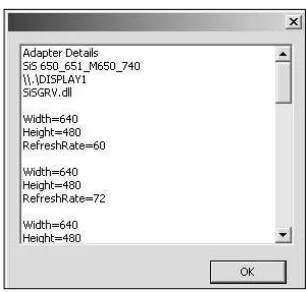
addItemToList(“Adapter Details”); addItemToList(ident.Description); addItemToList(ident.DeviceName); addItemToList(ident.Driver);
I’m calling the addItemToList helper function to add the details to be shown in a dialog box later.
// collects the modes this adapter has UINT numModes = pD3D->GetAdapterModeCount(
D3DADAPTER_DEFAULT, D3DFMT_X8R8G8B8);
Next, I’m using GetAdapterModeCount to get the number of modes. I then use this number in the for loop that follows. Here you start looping through the modes and gathering the details for each one.
for (UINT i=0; I < numModes; i++) {
33 Taking the Game Full Screen
char modeString[255]; // This is a temporary char array // Get the displaymode structure for this adapter mode pD3D->EnumAdapterModes(D3DADAPTER_DEFAULT,
D3DFMT_X8R8G8B8, i,
&mode);
// Draw a blank line in the list box addItemToList(“”);
// Output the width
sprintf(modeString, “Width=%d”,mode.Width); addItemToList(modeString);
// Output the height
sprintf(modeString, “Height=%d”,mode.Height); addItemToList(modeString);
// Output the refresh rate
sprintf(modeString, “Refresh Rate=%d”,mode.RefreshRate); addItemToList(modeString);
}
return true; }
This is a simple helper function that takes one parameter of STL stringand adds it to the end of a vector. By the end of the initDirect3D function, the vector will include all the details concerning the video adapter.
// The adapterDetails variable is a vector that contains strings; each string will // hold the information for the different video modes
std::vector<std::string> adapterDetails; void addItemToList(std::string item) {
adapterDetails.push_back(item); }
Figure 2.8 shows the dialog box and the details that you should get when you run this example. Because everyone has different video cards, expect the details to vary based on the machine that this is run on.
t i p
The Standard Template Library (STL) provides many useful items, such as the string and vector types that you’ve already used, as well as others. Using STL types also eases your work when porting to additional platforms, such as UNIX or gaming consoles.
Chapter Summary
This chapter covered a lot of information, ranging from the beginnings of a project to a workable DirectX application. These examples might not show much, but they are the building blocks for everything you will do going forward.
What You Have Learned
In this chapter, you learned the following:
■ How the Direct3D object and Direct3D device are created
■ The proper method for clearing the screen each frame
■ The changes to a standard message loop that need to be made for games
■ How to add the DirectX libraries to your game projects
■ How to determine the video adapter in a system and what its capabilities are
The next chapter introduces surfaces and the creation of animated sprites.
Review Questions
You can find the answers to Review Questions and On Your Own exercises in Appendix A, “Answers to End-of-Chapter Exercises.”
1. What’s the first DirectX object that needs to be created in any application?
2. What does the GetAdapterCount function do?
3. The D3DFORMAT of D3DFMT_A8R8G8B8 defines how many bits for each color?
4. What DirectX function is required to blank the screen to a specific color? 5. What function do you use to find the number of modes that are available on a
video adapter?
On Your Own
1. Change example 2 on the CD-ROM to clear the screen to green instead of blue. 2. Update example 4 on the CD-ROM to search your system for the display modes
chapter 3
Surfaces, Sprites,
and Salmon
S
prite-based and 2D games still have a big part to play in the game market. Not allgames require the latest in 3D video hardware; fun and timeless games like Tetris
are completely 2D and still immensely popular. This chapter introduces you to some simple ways to use DirectX for the creation of sprite-based games.
Here’s what you’ll learn in this chapter:
■ What surfaces are and how they can be used
■ How to gain access to the back buffer
■ How to create offscreen surfaces
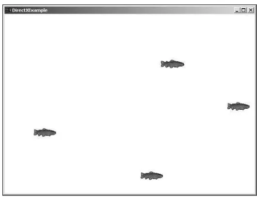
■ How to load a bitmap easily
■ How to create and use sprites
■ How to animate sprites
■ How to use timers for smooth animation
You’ve Just Touched the Surface
Surfaces are an integral part of DirectX. Surfaces are areas within memory that are used for the storage of image information. They store images and textures and are used to rep-resent the display buffers. Surfaces are stored internally as a contiguous block of memory, usually residing on the video card, but occasionally in main system memory.
This chapter covers two specific types of surfaces: display buffers and offscreen surfaces.
The Display Buffers
There are two display buffers that you have to worry about: the front buffer and the back buffer. These are the areas of video memory where your game is drawn.
The front buffer is the surface that represents the viewable area of your game window. Everything that you can see within your application window is considered the front buffer or drawing area. In full-screen mode, the front buffer is expanded to fill the whole screen. The second buffer is the back buffer. As you’ll recall from earlier, the back buffer is where you perform all the drawing. After the drawing to the back buffer is complete, you use the Present function to display its contents.
The back buffer is created during the call to CreateDevice by specifying the BackBufferCount parameter in the D3DPRESENT_PARAMETERS structure.
n o t e
Attempting to draw directly to the front buffer results in your graphics flashing and tearing. Graph-ics should always be drawn to the back buffer first, and then displayed using the Present method.
Offscreen Surfaces
Offscreen surfaces are areas of video or system memory that hold the graphics that your game needs. For instance, if you’re creating an overhead role-playing game, you need an area to store the tiles that represent the different terrain, as well as the graphics for your characters. An off-screen surface would be a perfect choice for this task.
Graphics for use within DirectX are usually bitmaps.
Fig-ure 3.1 shows an example bitmap that would be loaded Figure 3.1 Example tiles for a
for use in your game. 2D role playing game.
n o t e
Some older video cards allow only for the creation of offscreen surfaces that are the same resolu-tion as the primary buffer. Newer video cards allow for crearesolu-tion of larger surfaces.
Offscreen surfaces, represented by the IDirect3DSurface9 interface, are created using the
function CreateOffscreenPlainSurface. You must call this function for each surface you
want to create. The CreateOffscreenPlainSurface function is defined as follows:
HRESULT CreateOffscreenPlainSurface(
UINT Width, // width of the surface
37 You’ve Just Touched the Surface
D3DFORMAT Format, // D3DFORMAT type
DWORD Pool, // memory pool
IDirect3DSurface9** ppSurface, // resulting surface pointer HANDLE* pHandle // always NULL
);
CreateOffscreenPlainSurface has six parameters:
■ Width. This parameter is the width in pixels that the created surface should be.
■ Height. This is the height in pixels of the created surface.
■ Format. This is the D3DFORMAT that the surface should use.
■ Pool. This is the memory location in which the surface will be placed. You can
choose from four types of memory pools:
• D3DPOOL_DEFAULT. The system places the resource in the most appropriate type of
memory. This can be either in video or system memory.
• D3DPOOL_MANAGED. The resource is copied to the appropriate memory when
needed.
• D3DPOOL_SYSTEMMEM. The surface is created in system memory.
• D3DPOOL_SCRATCH. Again, this is created in system memory but is not directly
accessible by DirectX.
■ PpSurface. This is a pointer to an IDirect3DSurface9 interface. This variable holds the
reference to the surface after it is created.
■ pHandle. This is a reserved parameter and should always be NULL.
Next is a sample call to CreateOffscreenPlainSurface. This sample creates a surface that is
640 ×480 resolution and has the display format of D3DFMT_X8R8G8B8.
hResult = CreateOffscreenPlainSurface(
640, // the width of the surface to create 480, // the height of the surface to create D3DFMT_X8R8G8B8, // the surface format D3DPOOL_DEFAULT, // the memory pool to use
&surface, // holds the resulting surface
NULL); // reserved; should be NULL
// Check the return value to make sure that this function call was successful if (FAILED(hResult))
return NULL;
Loading a Bitmap to a Surface
Because bitmaps are commonly used for graphics within Windows, I’ll be using this
for-mat exclusively in the examples. DirectX provides functions within the D3DX library that
D3DX Explained
The D3DX library is a collection of commonly used functions that Microsoft has provided with the DirectX SDK. Included in this collection are functions to do any of the following:
■ Handle loading images
■ Load and manipulate 3D meshes
■ Perform shader effects
■ Make transforms and rotations simpler
You can use functions within the D3DX library by including the d3dx9.h file and linking to
d3dx9.lib.
n o t e
Many image formats are used in game development today. Some companies use common formats such as bitmap or Targa, whereas others create their own proprietary formats to protect their art assets. Rarely are games released with images that are editable by the end user.
The function D3DXLoadSurfaceFromFile performs the loading of a source bitmap into an
off-screen surface. The D3DXLoadSurfaceFromFile function is defined as follows:
HRESULT D3DXLoadSurfaceFromFile( LPDIRECT3DSURFACE9 pDestSurface, CONST PALETTEENTRY* pDestPalette, CONST RECT* pDestRect,
LPCTSTR pSrcFile, CONST RECT* pSrcRect, DWORD Filter,
D3DCOLOR ColorKey, D3DXIMAGE_INFO* pSrcInfo );
D3DXLoadSurfaceFromFile takes eight parameters:
■ pDestSurface. A pointer to the surface that should hold the incoming bitmap image.
■ pDestPalette. A pointer to a PALEETTEENTRY structure. This parameter is used only for
256-color bitmaps. For 16-, 24-, and 32-bit images, this parameter should be set to the value of NULL.
■ pDestRect. A pointer to a RECT structure that represents the rectangular area of the
39 You’ve Just Touched the Surface
■ pSrcFile. A string representing the file name of the bitmap to load.
■ pSrcRect. A pointer to a RECT structure that represents the area of the source bitmap
that should be loaded into the surface.
■ Filter. A D3DX_FILTER type that specifies the type of filtering that should be applied.
■ ColorKey. The D3DCOLOR format of the color that should be used for transparency.
The default color value is 0.
■ pSrcInfo. A pointer to a D3DXIMAGE_INFO structure. This structure holds information
about the source bitmap file, such as width, height, and bit depth.
Here’s an example of a simple call to D3DXLoadSurfaceFromFile, which loads a bitmap called
test.bmp into an offscreen surface. Remember: This surface must first be created with a call
to CreateOffscreenPlainSurface.
IDirect3DSurface9* surface;
hResult = D3DXLoadSurfaceFromFile( surface, NULL, NULL, “test.bmp”, NULL,
D3DX_DEFAULT, 0,
NULL ); if ( FAILED( hResult ) )
return NULL;
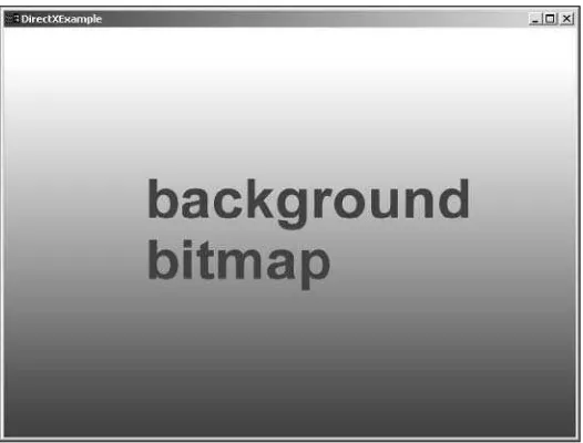
Following this call, the bitmap will reside in memory and be ready for use in your game.
Using DirectX to Render a Bitmap
Now that you’ve seen how to create a surface and how to load a bitmap into it, it’s time to
display it. To do this, you have to make some changes to the Render function that was
cre-ated earlier.
The previous Render function looked like this.
/********************************************************************* * Render(void)
*********************************************************************/ void Render(void)
{
// Check to make sure you have a valid Direct3D device if( NULL == pd3dDevice )
// Clear the back buffer to a blue color pd3dDevice->Clear( 0, NULL, D3DCLEAR_TARGET,
D3DCOLOR_XRGB(0,0,255), 1.0f, 0 ); // Present the back buffer contents to the display pd3dDevice->Present( NULL, NULL, NULL, NULL ); }
To get the bitmap shown on the screen, you’ll need to use the StretchRect function. StretchRect performs rectangular copies between two surfaces.
The StretchRect function is defined as follows:
HRESULT StretchRect(
IDirect3DSurface9 *pSourceSurface, CONST RECT *pSourceRect,
IDirect3DSurface9 *pDestSurface, CONST RECT *pDestRect,
D3DTEXTUREFILTERTYPE Filter );
StretchRect has the following parameters:
■ pSourceSurface. A pointer to the offscreen surface that has already been created.
■ pSourceRect. A pointer to a RECT structure that holds the area to be copied. If this
parameter is NULL, the full source surface is copied.
■ pDestSurface. A pointer to the destination surface. In most cases, this will be a
pointer to the back buffer surface.
■ pDestRect. A pointer to the RECT structure that represents the area on the destination
surface where the copy will be placed. This parameter can be NULL if no destination
RECT is needed.
■ Filter. The filter type to apply to this copy. Sending the value of D3DTEXF_NONE
indi-cates that no filtering should be applied.
You might be wondering how you get a pointer to the back buffer surface. The aptly
named function GetBackBuffer does the trick. A standard call to this function would look
like this:
GetBackBuffer( 0, // a value that represents the swap chain
0, // index of the buffer chain;
// 0 if only one back buffer is available D3DBACKBUFFER_TYPE_MONO, // the only valid type