UNIVERSITI TEKNIKAL MALAYSIA MELAKA
PSM TITLE (High Power Inverter in Ambulance)
This report submitted in accordance with requirement of the Universiti Teknikal Malaysia Melaka (UTeM) for the Bachelor’s Degree in Electrical Engineering
Technology (Industrial Electronic) (Hons.)
by
STUDENT NAME (ABDUL MUHAIMIN BIN ABDUL LATIFF) MATRIX NUMBER (B071210526)
IC NUMBER (900415095085)
UNIVERSITI TEKNIKAL MALAYSIA MELAKA
BORANG PENGESAHAN STATUS LAPORAN PROJEK SARJANA MUDA
TAJUK: High Power Inverter in Ambulance
SESI PENGAJIAN: 2014/15 Semester 2
Saya ABDUL MUHAIMIN BIN ABDUL LATIFF
mengaku membenarkan Laporan PSM ini disimpan di Perpustakaan Universiti Teknikal Malaysia Melaka (UTeM) dengan syarat-syarat kegunaan seperti berikut:
1. Laporan PSM adalah hak milik Universiti Teknikal Malaysia Melaka dan penulis. 2. Perpustakaan Universiti Teknikal Malaysia Melaka dibenarkan membuat salinan
untuk tujuan pengajian sahaja dengan izin penulis.
3. Perpustakaan dibenarkan membuat salinan laporan PSM ini sebagai bahan pertukaran antara institusi pengajian tinggi.
4. **Sila tandakan ( )
SULIT
TERHAD
TIDAK TERHAD
(Mengandungi maklumat yang berdarjah keselamatan atau kepentingan Malaysia sebagaimana yang termaktub dalam AKTA RAHSIA RASMI 1972)
(Mengandungi maklumat TERHAD yang telah ditentukan oleh organisasi/badan di mana penyelidikan dijalankan)
(TANDATANGAN PENULIS)
Tel : +606 234 6623 | Faks : +606 23406526
Rujukan Kami (Our Ref) : Rujukan Tuan (Your Ref) :
16 DEC 2015
Pustakawan
Perpustakaan UTeM
Universiti Teknikal Malaysia Melaka Hang Tuah Jaya,
76100 Durian Tunggal, Melaka.
Tuan/Puan,
PENGKELASAN LAPORAN PSM SEBAGAI SULIT/TERHAD LAPORAN PROJEK SARJANA MUDA TEKNOLOGI KEJURUTERAAN PEMBUATAN (COURSE NAME): ABDUL MUHAIMIN BIN ABDUL LATIFF
Sukacita dimaklumkan bahawa Laporan PSM yang tersebut di atas bertajuk “High Power Inverter in Ambulance” mohon dikelaskan sebagai *SULIT / TERHAD untuk tempoh LIMA (5) tahun dari tarikh surat ini.
2. Hal ini adalah kerana IANYA MERUPAKAN PROJEK YANG DITAJA OLEH SYARIKAT LUAR DAN HASIL KAJIANNYA ADALAH SULIT.
Sekian dimaklumkan. Terima kasih.
Yang benar,
________________
Tandatangan dan Cop Penyelia
* Potong yang tidak berkenaan
NOTA: BORANG INI HANYA DIISI JIKA DIKLASIFIKASIKAN SEBAGAI
SULIT DAN TERHAD. JIKA LAPORAN DIKELASKAN SEBAGAI TIDAK
iv
DECLARATION
I hereby, declared this report entitled “PSM Title” is the results of my own research except as cited in references.
Signature : ……….
Author’s Name : ABDUL MUHAIMIN BIN ABDUL LATIFF
v
APPROVAL
This report is submitted to the Faculty of Engineering Technology of UTeM as a partial fulfillment of the requirements for the degree of Bachelor of Engineering Technology (Industrial Electronic) (Hons.). The member of the supervisory is as follow:
……… (Project Supervisor)
vi
ABSTRAK
Penyongsang elektronik kuasa menjadi lebih popular untuk pelbagai industri yang melibatkan sokongan bekalan kuasa dan aplikasi didalam motor. Pelbagai jenis topologi penyongsang telah dicadangkan dengan kepelbagaian tahap kuasa pada penyongsang samada kuasa tinggi atau penyongsang kuasa yang rendah. Projek ini adalah untuk membangunkan satu penyongsang kuasa tinggi menggunakan komponen elektronik. Projek ini menggabungkan pengetahuan elektrik dan elektronik. Objektif projek ini adalah untuk membangunkan satu litar penyonsang yang akan menukar arus terus (kereta bateri ) kepada voltan arus alternatif ( ). Arus terus akan dipisahkan kepada denyutan digital ( & ) mengunakan bipolar Pusle Witdh Modulation yang menggunakan dua unit �� digabungkan dengan comparator sebelum ia dialirkan ke bahaguan pesuisan mengunakan komponen kuasa yang tinggi untuk mendapatkan voltan alternatif. Hasil keluaran akan meningkat kepada menggunakan kuasa tinggi untuk meningkatkan pengubah untuk dibekalkan ke peralatan elektronik perubatan di dalam ambulans. Komponen yang akan digunakan mempunyai keupayaan kuasa yang tinggi dan ianya boleh meningkatkan kos kerana kesukaran untuk mendapatnya.
vii
ABSTRACT
Power electronic inverters are becoming more and more popular for various industrial for power supply backup and drive application. Many kind of inverter topologies have been proposed with many level of power for inverter such high power and low power inverter. This project is to develop an high power inverter using the electronic component. This project focuses on direct current (DC) to alternating current (AC) power inverters, which aim to efficiently transform a low DC input to high AC output, and this power will be suit for usage of electric equipment in ambulance. The objective of this project is to develop an inverter circuit which will convert the car battery to alternate current ( ). The direct curent will be break into pulses through bipolar pulse width modulation using two unit �� combined with comparator before it flows through switching high power components to obtain alternate current voltage. The output voltage will be increase to
using step-up transformer to supply the medical electronic equipment in ambulance. The components that will be use are high power capability and may increase the cost because hard to obtain in marketplace.
viii
DEDICATION
This project and research work is dedicated to my wife, my beloved parents and siblings for their devoted caring throughout my life, my loving brother and sisters
ix
ACKNOWLEDGEMENT
First of all, I would like to express my sincere thanks and indebted to Mr. IR Nik Azran Bin Abd. Hadi as my supervisor, thank you very much for accept
me as one of your PSM student and the collaborative leadership that you show will
always I remembered. And also special thanks to my co-supervisor Mrs. Raeihah Binti Mohd Zain. I also would like to thank to my PSM 1 panel
Mr. Fareez Ezwan Bin Mohd Sani and Mrs. Halma Binti Johari who gave me more idea on my project.
I would like to express my special thanks and a very down to earth and full with sense of humour-great experience to the Faculty of Engineering Technology (FTK) on putting into practice the Final Year Project as a compulsory chore for the third year students prior to complete their course.
I also wish to extend heartfelt thanks to my friends Fidaus Zainal, Nizam, Ikhwan, Syira Sufian, Ida Fairuz, Ibrahim and my entire classmate for your help and support during this three years in University Technical Malaysia Melaka. The memory we spent together will not I forget.
Finally, I wish to thank to Shahidah Binti Shamsul Babri, my patient wife. Not
forget for my lovely father, Abdul Latiff Bin Nazardin, my lovely mother, Rohayani Binti Hashim, elder brother Muhammad Maahi Bin Abdul Latiff, younger
brother Muhammad Najmuddin Bin Abdul Latiff and my sister in law, Maisarah Binti Mansor for their support. I love you all so much and also a big of
appreciation to all lectures for their encouragement, strength and support.
x
TABLE OF CONTENT
Abstrak vi
Abstract vii
Dedication viii
Acknowledgement ix
Table of Content xi
List of Tables xvi
List of Figures xvii
List Abbreviations, Symbols and Nomenclatures xx
CHAPTER 1: INTRODUCTION
1.1 Introduction 1
1.2 Problem analysis 2
1.3 Project Objective 3
1.4 Project Scope 4
CHAPTER 2: LITERATURE REVIEW
2.1 Direct Current input voltage 5
2.1.1 Batteries (Car Battery) 6
2.1.1.1 Type of Battery
2.1.1.2 Battery capacity rating
2.2 Alternating Current input voltage 8
2.2.1 AC power supply frequencies 2.2.2 AC analysis calculation 2.2.3 AC vs DC
2.3 Inverter 10
2.3.1 Inverter output waveform
xi
TABLE OF CONTENT
2.4 Electronic switch type 13
2.4.1 Transistor 13
2.4.1.1 Advantage of transistor over Vacuum Tubes 2.4.1.2 Type of transistor
2.4.2 Bipolar Junction Transistor (BJT) 14
2.4.3 Field-effect Transistor (FET) 15
2.4.4 Metal Oxide Semiconductor Field Effect Transistor (MOSFET) 16 2.4.4.1 P channel
2.4.4.2 N channel
2.4.4.3 Low Side and High Side
2.4.5 Power MOSFET 17
2.4.5.1 Switch operation of Power MOSFET 2.4.5.2 Self-aligned gate
2.4.5.3 Over voltage drive 2.4.5.4 Threshold voltage
2.5 Output of inverter 19
2.5.1 Modified sine wave 20
2.6 Which part of inverter that’s control the voltage up to 240V? 20 2.6.1 Analysis of transformer equation
2.6.2 Identify formula
2.6.3 Type of transformer 21
2.6.4 Energy losses of transformer
2.6.5 Effect of frequency in transformer 24
2.7 Circuit protection and snubbers 25
xii
TABLE OF CONTENT
CHAPTER 3: METHODOLOGY
3.1 Project Planning 27
3.2 Gantt Chart 29
3.3 Ambulance electronic equipment 30
3.1.1 Power analysis of equipment’s used 31
3.1.2 Total the power usage 31
3.4 Project Development of Inverter 32
3.4.1 Generator Unit 34
3.4.2 Control Unit 38
3.4.3 Output Unit 43
3.5 Inverter input 46
3.5.1 Calculation of Power Input
3.5.2 Runtime of battery
3.6 Snubber & Circuit Protection 47
3.7 PCB layout 48
3.8 Etching Process 50
xiii
TABLE OF CONTENT
CHAPTER 4: RESULT & DISCUSSION
4.1 Hardware implementation and discussion 53
4.1.1 Generator Unit 53
4.1.2 Control Unit 62
4.1.3 Output Unit 70
4.1.4 Complete circuit
CHAPTER 5: CONCLUSION & FUTURE WORK
5.1 Conclusion 75
5.2 Problem 76
5.3 Recommendation 77
5.4 Future work 77
Reference 78
xiv
LIST OF TABLES
2.1 2.2
Comparison between AC and DC input voltage Operation of overdrive voltage
9
List of electronic equipment in ambulance Operation of H-Bridge configuration
Function table for the waveform generator of generator unit Function table for the comparator of generator unit
xv 1.1 Inverter Block Diagram
3 1.2
2.1
Chart of workspace
Block diagram to build an inverter
4
One of inverter that now in market with modified sinusoidal output.
PWM signal generator input and output Type of transistor in marketplace Symbol of BJT NPN and PNP
Symbol of FET n-channel and p-channel
Type of output of inverter that can be produce for AC Inductive Load Circuit with snubber
LC filtering circuit Project Flowchart
Nebulizer compressor ABN and Patient pulse monitor Generator unit circuit connection using IC8038 H-bridge circuit configuration using N-channel MOSFET driver LT1158 pin configuration
The current output of inverter without inductance filtering The current output of inverter with inductance filtering
PCB layout of P-N h-bridge constructed using ARES PROTEUS PCB layout of triangular and sine wave generator with MOSFET driver.
3D visual of H-bridge
3D visual of Generator circuit using PROTEUS Etching Machine
Etching Solution and Container construction Example of drill bit used for drilling hole on PCB Example of soldering station and solder
xvi
PCB board after soldering process IC8038 Top View Pin configuration
Circuit diagram of sine waveform for hardware and simulation Sinusoidal wave output with 50 Hz from oscilloscope view The AC voltage measured through pin 2 ICL8038
The DC output measured through pin 2 ICL8038
Wiring diagram of circuit for modulation signal frequency Triangular waveform output after pin 3 probe to oscilloscope The measured DC and AC voltage of triangular waveform LM393 comparator IG configuration
The PWM output produce from pin 1 of LM393
Combination of two input wave input to comparator circuit. Wiring diagram for LT1158 to make bipolar switching.
The output of LT1158 where the yellow is probe to pin 15 while blue is probe to pin 9.
H-bridge circuit will be control ON/ OFF at two terminal below. The H-bridge output graph effect by VG
Q1 and Q4 is on after Vg is supplied while Q2 and Q3 connect to ground.
The saturation mode and triode mode for MOSFET
The structure of N-channel MOSFET for electron flow operation H-bridge circuit using P-channel and N-channel
PWM output is filter to get sine wave 50 Hz
Transformer input of 12 V, 60A and output 240 V, 3A The complete circuit of High Power Inverter
xvii
LIST OF ABBREVIATIONS, SYMBOLS AND
NOMENCLATURE
W - Watt
AC - Alternative current
DC - Direct current
PWM - Pulse Width Modulation
A / Amp - Ampere
V - Volt
PIC - Programmable Integrated Circuit VDC - Voltage of direct current
VIN - Voltage input
VO - Voltage output
VAC - Voltage of alternative current IDC - Current of direct current IAC - Current of alternative current
L - Inductor
C - Capacitor
BJT - Bipolar junction transistor FET - Field effect transistor
MOSFET - Metal Oxide Semiconductor Effect Transistor
etc - et cetera
H - Hours
Hz - Hertz
< - Less than
> - More than
Q - MOSFET
+VE - POSITIVE
1
1.0 Introduction
Power electronic is a rapidly growing in Electrical Engineering. The field of power electronics deal with application of solid-state electronics to the control and conversion of electric power.[1] It also refers to a subject of research in electronic and electrical engineering which deals with the design, control, computation and integration of nonlinear, time-varying energy-processing electronic systems with fast dynamics.
Electrical power can be converted into two different types of power: direct current (DC) and alternating current (AC). [2] These two types of power can be converted through four different methods. These methods include AC to DC, DC to AC, DC to DC and AC to AC. The conversion of DC to AC can be done through an inverter circuit while a rectifier (full bridge) is an electronic circuit that will convert AC power to DC power. The other two methods require either a DC to DC convert or an AC to AC converter only convert the input to another voltage level for output without changing the type of input. As the world become more innovative, each of four different type of circuit can be further expanded depending on what output are desired.
There are many methods of building inverter such as multilevel inverter, half bridge inverter and full bridge converter (H-bridge) with using low pass LC filter to get the smooth of sinusoidal output. And the only way to control the switching is only using generating signal.
2 For low power inverter, it can be done by combinations of 555 timer and flip flop, also can generate using PIC microcontroller since it has their own PWM in the package. But for high power of inverter, PWM is widely used to control the switching especially for induction motor, photovoltaic solar power and etc. PWM technique is divided into two ways includes unipolar and bipolar inverters method.
1.1 Problem Analysis
The failure of main power supply or the power line causes interruption in emergency situation because of unexpected phenomena happened Malaysia today. This problem is worst when emergency operation need to be done to save the life immediately. Such example undelivered mother needs minor operation to deliver the baby in time but the main power supply cannot be reach at the moment. Besides that, a situation an accident at highway, it will take time to reach to hospital and the patience need to be treat immediately but there are no electrical supply to switch ON the electric medical equipment such as monitoring the pulse and respiratory assistance equipment.
Therefore, the inverter is designed to overcome this problem since every house has one car. [8] The inverter circuit will convert DC voltage from the battery to AC voltage which can be used by the most of medical electronic equipment. These combinations will produce a high power inverter that possibly reach to 1000 watt of power that can last long depend on the power of each equipment needs.
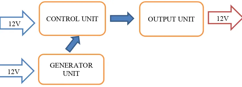
The high power inverter consist three main circuits:
3 Figure 1.1: Inverter block diagram
The control unit and generator unit will be powered by 12 VDC battery. [3] The generator circuit will use PWM method by using generator IC while the control unit will use power MOSFET that capable to handle the max power expected is . The output after filtering will boost up using step-up transformer to the then will supply the electrical equipment wherever the DC supply (12 V car battery) is available.
1.2 Project Objective
The objectives of this project are:
i. To develop an inverter circuit which can convert dc voltage to ac voltage
ii. To boost the output voltage to 240V ac from 12V by using a transformer
iii. To build the inverter that capable to handle the max power of 1000Watt.
CONTROL UNIT
GENERATOR UNIT
OUTPUT UNIT 12V
12V
4
1.3 Project Scope
To realize this project, a few scopes were determined. The project scopes
are very important to make sure that the project is on the right rails. Thescopes
ofthis project are shown in Figure 1.2 below.
Figure 1.2: Chart of workscope
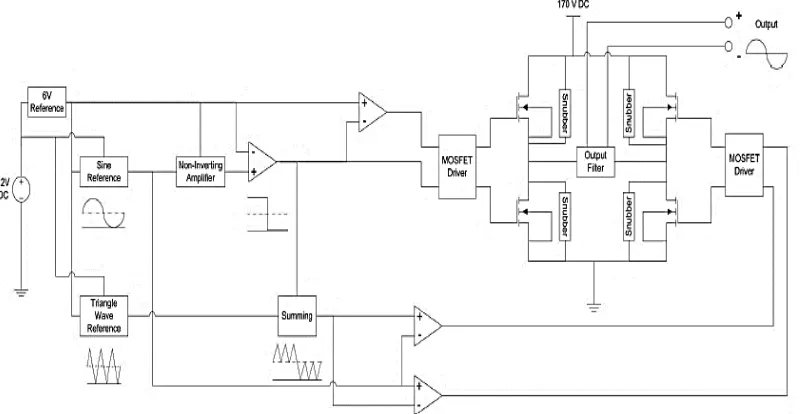
5 To do this research it required focusing on the main point of inverter and absolutely understands for each part of circuit that will be used in project such the diagram show in Figure 2.1 below.
Figure 2.1: Block diagram to build an inverter
2.1 Direct Current Input Voltage
An inverter circuit does not increase any of power; it will only change the polarity of input. The power is controlled by input DC battery which the voltage of car battery is and the different of each model is the capacity of current. [2] By conservation of energy of real and reactive this said that:
� � � = � ... (2.1)
6
A DC power supply is one that supplies a voltage of fixed polarity (either positive or negative) to its load. Direct current is the unidirectional flow of electric charge with other means that the current flowing in one direction only from positive (+) to negative (-). In DC analysis we basically know the basic of formula are:
��� = � � � � � � �� ... (2.2)
� = � � � ��� ... (2.3)
Direct current is produced by sources such as batteries, thermocouples, solar cells, commutator-type electric machines of the dynamo type and generator.
2.1.1.1 Car Battery
A lead-acid storage battery is an electrochemical device that produces voltage and delivers electrical current. [4] The battery is the primary “source” of electrical energy used in vehicles today. It’s important to remember that a battery does not store electricity rather it stress a series of chemicals, and through a chemical process electricity is produced. Basically, two different types of lead in an acid mixture react to produce electrical pressure called voltage. This electrochemical reaction changes chemical energy to electrical energy and is the basic for the all automotive batteries.