i
“I/We admitted had read this report and from my/our view, this report is eligible in scope and quality for the purpose of fulfilling the requirement for the Bachelor of
Mechanical Engineering (Design and Innovation)”
Signature :………..
First supervisor :………..
Date :………..
Signature :………..
Second supervisor :………..
ii
“I hereby declared that this thesis titled
„The Design of a Pre-Assembly of Blood Collection Tube Mechanism‟ is the result of my own effort except as cited in references”.
iii
ACKNOWLEDGEMENTS
Thanks dear Lord the most merciful for this opportunity that allowing me to finish my PSM 1 report with ease.
A million thanks to Mr. Nazim (supervisor), lab technicians, and fellow lecturers who had guided and supported me throughout the whole process of completing my PSM report. Lastly, I also would like to thank all of my colleagues whether in UTeM or not for their contribution in sources, journal and a whole lot of studying tools provided by them.I am gratified to the Head of Department of Mechanical Engineering (Design and Innovation) and the members of the staff at the University the constant encouragement and the valuable inputs from time to time throughout the completion of this report.
iv
ABSTRACT
v
ABSTRAK
vi
CONTENTS
CHAPTER CONTENTS PAGE
DECLARATION i
ACKNOWLEDGEMENT ii
ABSTRACT iii
CONTENT v
LIST OF FIGURE ix
LIST OF TABLE xiv
LIST OF APPENDIX xv
CHAPTER 1 INTRODUCTION
1.1 Introduction 1
1.2 Problem Statement 2
1.3 Objectives 3
1.4 Scope 3
CHAPTER 2 LITERATURE REVIEW
2.1 Introduction to Blood Collection Tube Assemblies 4
2.2 Venipuncture 5
2.3 Equipment Used 6
vii
2.4.1 Principles of vacutainer 7
2.5 Blood Collection Tubes Studies 8 2.5.1 Process involved into assembling all the parts 9 2.5.2 Converting the process from manual into 11
an automated system
2.5.3 Process flow of the blood collection tube assembly 14
2.6 Pneumatic Stepper Motor 15
2.6.1 Types of stepper motor 16
2.6.2 Applications of stepping motor 17
2.7 Vibratory Bowl Feeder 19
CHAPTER 3 METHODOLOGY
3.1 Introduction 21
3.2 Project flow 22
3.3 Research 24
3.4 Data Analysis 24
3.5 Define Design Needs 25
3.6 Product Design Specification 26
3.7 Concept Generation 27
3.7.1 Morphology chart for assembly (a) 28 3.7.2 Morphology chart for assembly (b) 29
3.8 Concept for Assembly (A) 30
3.8.1 Concept 1(a) 30
3.8.2 Concept 2(a) 31
viii
3.9 Concept for Assembly (b) 33
3.9.1 Concept 1(b) 33
3.9.2 Concept 2(b) 34
3.9.3 Concept 3(b) 35
3.10 Concept Selection 36
3.10.1 Matrix selection 37
3.10.2 Selected concepts 39
3.10.2.1Assembly (a) 39
3.10.2.2Assembly (b) 40
CHAPTER 4 RESULT
4.1 Detail Design 42
4.2 Alignment Section 42
4.2.1 Bowl Feeder System 43
4.2.2 Riser System 44
4.2.3 Camera System 45
4.2.4 Stopper System 46
4.3 Transfer Section 46
4. 4 Hammer Section 47
CHAPTER 5 ANALYSIS AND DISCUSSION
5.1 Specification of the Vibrating Bowl Feeder 49
5.2 System Flow 50
5.3 How The System Works? 52
ix 5.3.1.1 Ensuring Only Parts with Correct 55
Orientation Makes It Way Out Of the Bowl.
5.3.2 Parts Transfer System 60
5.3.3 Hammer Section 61
5.4 Parts of the Bowl Feeder System 67
5.4.1 The Alignment Section 68
5.4.1.1 Bowl Feeder System 69
5.4.1.2 Stopper System 71
5.4.1.3 Camera System 73
5.4.1.4 Riser System 78
5.4.1.5 Air Jet 79
5.4.2 Transfer Section 80
5.4.2.1 Gravity Track 81
5.4.1.2 Tube Magazine 82
5.4.3 Hammer Section 83
5.4.3.1 Hammer Base and Tube Holder 84 5.4.3.2 Angular Stepper Motor 85
5.4.3.3 Pneumatic Hammer 86
CHAPTER 6 CONCLUSION AND RECOMMENDATION
6.1 Conclusion 87
6.2 Future of the design 88
REFERENCES 90
x
LIST OF FIGURES
NO. FIGURE PAGE
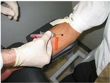
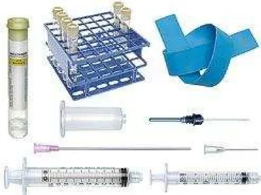
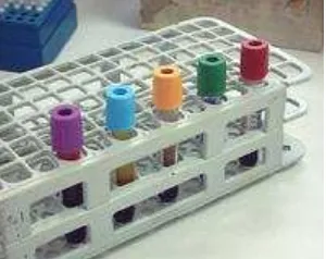
Figure 2.1: Venipuncture procedure (source: Wikipedia.com) 5 Figure 2.2: blood collection kit (source: salvin.com) 6 Figure 2.3: vacutainers on a rack (source: Wikipedia.com) 7
Figure2.4: both parts facing upward 9
Figure2.5: placing the rubber stopper onto the top cap 9
Figure2.6: assembled top half 9
Figure2.7: placing the top half onto the tube 9 Figure2.8: assembled blood collection tube 10 Figure2.8: assembled blood collection tube 10
Figure2.9: both parts facing upward 11
Figure2.10: placing the rubber valve onto the top cap 11
Figure2.11: assembled top half 12
xi Figure2.18: typical vibratory bowl feeder 19
Figure3.1: process flow of blood collection tube assembly project 23
Figure 3.1: assembled top half 27
Figure 3.2: placing the top half onto the tube 27
Figure 3.3: Assembly (a) 28
Figure 3.4: Assembly (b) 29
Figure 3.5: Concept 1(a) 30
Figure 3.6: Concept 2(a) 31
Figure 3.7: Concept 3(a) 32
Figure 3.8: Concept 1(b) 33
Figure 3.9: Concept 2(b) 34
Figure3.10: concept 3(b) 35
Figure 3.11: Concept 1(a) 39
Figure3.12: concept 3(b) 40
Figure 4.1: the full blood collection tube pre-assembly system design 42
Figure 4.2: alignment section 42
Figure 4.3: bowl feeder 43
Figure 4.4: base 43
Figure 4.5: guard rail 43
Figure 4.6: leaf spring 43
Figure 4.7: back view of alignment section + riser and air jet system 44
Figure 4.8: the riser unit 44
Figure 4.9: whole camera system 45
Figure 4.10: rod 1 45
Figure 4.11: rod 2 45
Figure 4.12: camera holder 45
xii
Figure 4.14: tube magazine 46
Figure 4.15: gravity track 46
Figure 4.16: hammer section 47
Figure 4.17: hammer section assemblies 47
Figure 4.18: hammer base 47
Figure 4.19: pneumatic hammer 47
Figure 4.20: tube holder 47
Figure 5.1: vibrating bowl unit 48
Figure5.2: flow chart of system flow 50
Figure5.3: assembled top half 52
Figure5.4: electromagnet pulling the bowl downward 53 Figure5.5: feeder twisting effect on the bowl feeder 53
Figure5.6: bowl upward motion 54
Figure5.7: parts movement inside the bowl 55
Figure 5.8: track design 55
Figure 5.9: orientation (a) and orientation (b) 56 Figure 5.10: the Vision system in the design compared 56 with the real life design of industrial camera for Vision system.
Figure 5.11: position of riser 57
Figure 5.12: riser stopping part from moving 57
Figure 5.13: riser mechanism 58
Figure 5.14: correct orientation 58
Figure 5.15: wrong orientation 59
Figure 5.16: part blown by air jet 59
Figure 5.17: the air jet system 59
xiii Figure 5.20: tube being loaded into the tube magazine 61
Figure 5.21: hammer section and tube holder mechanism 62
Figure 5.22: original position 62
Figure 5.23: insertion position 63
Figure 5.24: parts in hammer position 63
Figure 5.25: hammer released 64
Figure 5.26: length of stroke is determined to ensure a working product. 64 Figure 5.27: maximum product length is 86.15mm 65
Figure 5.28: ejecting position 65
Figure 5.29: finished product falls down into container provided below. 66 Figure 5.30: the whole blood collection tube pre-assembly 67 automated system
Figure 5.31: front and back view of the bowl feeder mechanism 68 Figure 5.32: the bowl feeder system, without guard rail 69 Figure 5.33: real industrial bowl feeder 69 Figure 5.34: stopper in the design and the real industrial 71
stopper for screw manufacturing. 71
Figure 5.35: stopper dimensions 72
Figure 5.36: the camera system 72
Figure 5.37: camera system implementation 73 Figure 5.38: camera range of capture inside the box drawn 73 Figure 5.39 Point Gray Camera Flea®2 74
Figure 5.40: flow of camera and riser 74
Figure 5.41: riser system 75
Figure 5.42: the air jet system 78
Figure 5.42: parts that involves in the transfer section 79
xiv Figure 5.44: tube magazine dimensions and positioning 81
Figure 5.45: hammer section assemblies 82 Figure 5.46: hammer base and tube holder assembly 83 Figure 5.47: tube holder motor dimensions 84 Figure 5.48: BPS pneumatic stepping motor (source:www.bibus.ch) 85 Figure 5.49: pneumatic hammer dimensions 85 Figure 5.50: round cylinder, Series CPC 86
xv
LIST OF TABLES
NO. TABLE PAGE
Table 2.1: parts of blood collection tube 8
Table 2.2: Types of stepper motor 16
Table 2.3: Applications of stepping motor 17
Table3.1: design needs 25
xvi
LIST OF APPENDIX
A Drafting
B Gantt chart for PSM 1 and PSM 2 C Flow chart of PSM 1
1
CHAPTER 1
INTRODUCTION
1.1 Project Background
„Projek Sarjana Muda‟ is a compulsory syllabus needed for each student of Universiti Teknikal Malaysia Melaka, (UTeM) to participate and contribute their knowledge in order for them to receive their bachelor‟s degree in mechanical engineering. This goes for the PSM where students will be given a chance to prove themselves through series of theories, research, experiments, analysis, optimization and a whole lots more method known to the engineering world.
The project decided for my PSM is to design and possibly fabricate an assembly process of blood collection tube to be inserted into a vacuum chamber machine. The machine had been designed and fabricated within UTeM laboratory with collaboration from UPM.
2
phlebotomy. It is commonly vacuumed so the usage of syringes as in traditional method of phlebotomy is not needed.
By using a syringe, the patient‟s skin need to be punctured and by pulling the lever on the syringe, the blood is collected and then the collected blood will be inserted into a test tube where it will be stored for testing. When using a vacutainer, the process is a bit different where the blood does need to be transferred into another vessel after being taken but it is taken directly into the test tube that will hold it for further testing.
1.2 Problem Statement
Currently the tubes were assembled by hand and it will be arranged into its holder manually. It is a right option considering only a few blood collection tubes will be processed in a single run. The problem lies when we had designed a holder mechanism that could contain 100 tubes at a time. The process need to be automated where all the manual process before need to be converted to mechanical machineries.
Our concern in this PSM is the process on how the tube will be assembled. The tube itself consists of three different parts: the tube itself, stopper and the color coded cap. A process flow is need to be constructed and what types of machineries or devices to handle the process flow need to be decided.
3 Arrangements of the tubes into the holder also considered as a crucial part. 100 tubes need to be arranged into the holder into each of their slot provided without any manual process.
Sorting devices, positioning devices, mechanical insertion devices and a lot of sensors need to be considered in making this process cycle.
1.3 Objectives
To study and design a pre-assembly for blood collection tubes before the vacuum process takes place.
1.4 Scope
Conduct literature study regarding the topic given.
4
CHAPTER 2
LITERATURE REVIEW
2.1 Introduction to Blood Collection Tube Assemblies
The usage of an assembly line to assemble blood collection tube is still being kept a secret and one could only guess how the process look like and for that reason, the studies on this topic is going to be more to an assumption and we will find the most logical and appropriate way to assemble the blood collection to prepare them to be vacuumed. Even though the sources may be scarce but the main idea could still be found which is;
We will study the basic concept of a blood collection tube and how it works along with the biological knowledge alongside the devices. The standards of blood collection tube, dimensions and constraints manufacturers need to follow when making a blood collection tube.
5 other blood collection tube as well and our future ambition is to produce a process that could be used universally on all types of blood collection tube.
2.2 Venipuncture
In medicine, venipuncture or venepuncture is a process of subtracting intravenous access for the purpose of intravenous therapy or obtaining a sample of venous blood. The procedure usually performed by medical practitioners, including paramedic staffs, nurses or doctors.
Blood is most commonly obtained from the median cubital vein, on the anterior forearm (the side within the fold of the elbow). This vein lies close to the surface of the skin, and there is not a large nerve supply.
Phlebotomy (incision into a vein) is also the treatment of certain diseases such as hemochromatosis and primary and secondary polycythemia.
6
2.3 Equipment Used
There are many ways in which blood can be drawn from a vein. The best method varies with the age of the patient, equipment available and tests required.
Most blood collection in the US and UK is done with an evacuated tube system, such as the BD Vacutainer system or similar blood collection equipment consisting of a plastic hub, a hypodermic needle, and a vacuum tube. Under certain circumstances, a syringe may be used, usually with a butterfly needle, which is a plastic catheter attached to a short needle. In the developing world, where medical supply is crucial, a needle and syringe are still the most common method of drawing blood.
7
2.4 Vacutainer
Vacutainer is a registered brand of test tube specifically designed for venipuncture. It was developed in 1947 by Joseph Kleiner and is currently marketed by Becton, Dickinson and company. (Source: howstuffworks.com)
Figure 2.3: Vacutainers on a rack (source: Wikipedia.com)
2.4.1 Principles of Vacutainer
8
2.5 Blood Collection Tubes Studies
Chosen subject; UPM blood collection tube prototype Parts involved in the blood collection tube;
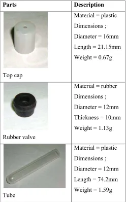
Table 2.1: Parts of blood collection tube
Parts Description
Top cap
Material = plastic Dimensions ; Diameter = 16mm Length = 21.15mm Weight = 0.67g
Rubber valve
Material = rubber Dimensions ; Diameter = 12mm Thickness = 10mm Weight = 1.13g
Tube