Theory and Problems of
ELECTRIC
CIRCUITS
Fourth Edition
MAHMOOD NAHVI, Ph.D.
Professor of Electrical Engineering
California Polytechnic State University
JOSEPH A. EDMINISTER
Professor Emeritus of Electrical Engineering
The University of Akron
sion of the publisher. 0-07-142582-9
The material in this eBook also appears in the print version of this title: 0-07-139307-2.
All trademarks are trademarks of their respective owners. Rather than put a trademark symbol after every occurrence of a trademarked name, we use names in an editorial fashion only, and to the benefit of the trademark owner, with no intention of infringement of the trademark. Where such designations appear in this book, they have been printed with initial caps. McGraw-Hill eBooks are available at special quantity discounts to use as premiums and sales promotions, or for use in cor-porate training programs. For more information, please contact George Hoare, Special Sales, at [email protected] or (212) 904-4069.
TERMS OF USE
This is a copyrighted work and The McGraw-Hill Companies, Inc. (“McGraw-Hill”) and its licensors reserve all rights in and to the work. Use of this work is subject to these terms. Except as permitted under the Copyright Act of 1976 and the right to store and retrieve one copy of the work, you may not decompile, disassemble, reverse engineer, reproduce, modify, create derivative works based upon, transmit, distribute, disseminate, sell, publish or sublicense the work or any part of it without McGraw-Hill’s prior consent. You may use the work for your own noncommercial and personal use; any other use of the work is strictly prohibited. Your right to use the work may be terminated if you fail to comply with these terms. THE WORK IS PROVIDED “AS IS”. McGRAW-HILL AND ITS LICENSORS MAKE NO GUARANTEES OR WAR-RANTIES AS TO THE ACCURACY, ADEQUACY OR COMPLETENESS OF OR RESULTS TO BE OBTAINED FROM USING THE WORK, INCLUDING ANY INFORMATION THAT CAN BE ACCESSED THROUGH THE WORK VIA HYPERLINK OR OTHERWISE, AND EXPRESSLY DISCLAIM ANY WARRANTY, EXPRESS OR IMPLIED, INCLUDING BUT NOT LIMITED TO IMPLIED WARRANTIES OF MERCHANTABILITY OR FITNESS FOR A PAR-TICULAR PURPOSE. McGraw-Hill and its licensors do not warrant or guarantee that the functions contained in the work will meet your requirements or that its operation will be uninterrupted or error free. Neither McGraw-Hill nor its licensors shall be liable to you or anyone else for any inaccuracy, error or omission, regardless of cause, in the work or for any dam-ages resulting therefrom. McGraw-Hill has no responsibility for the content of any information accessed through the work. Under no circumstances shall McGraw-Hill and/or its licensors be liable for any indirect, incidental, special, punitive, con-sequential or similar damages that result from the use of or inability to use the work, even if any of them has been advised of the possibility of such damages. This limitation of liability shall apply to any claim or cause whatsoever whether such claim or cause arises in contract, tort or otherwise.
standard texts and can be used by electrical engineering students as well as other engineereing and technology students. Emphasis is placed on the basic laws, theorems, and problem-solving techniques which are common to most courses.
The subject matter is divided into 17 chapters covering duly-recognized areas of theory and study. The chapters begin with statements of pertinent definitions, principles, and theorems together with illustrative examples. This is followed by sets of solved and supplementary problems. The problems cover a range of levels of difficulty. Some problems focus on fine points, which helps the student to better apply the basic principles correctly and confidently. The supplementary problems are generally more numerous and give the reader an opportunity to practice problem-solving skills. Answers are provided with each supplementary problem.
The book begins with fundamental definitions, circuit elements including dependent sources, circuit laws and theorems, and analysis techniques such as node voltage and mesh current methods. These theorems and methods are initially applied to DC-resistive circuits and then extended to RLC circuits by the use of impedance and complex frequency. Chapter 5 on amplifiers and op amp circuits is new. The op amp examples and problems are selected carefully to illustrate simple but practical cases which are of interest and importance in the student’s future courses. The subject of waveforms and signals is also treated in a new chapter to increase the student’s awareness of commonly used signal models.
Circuit behavior such as the steady state and transient response to steps, pulses, impulses, and exponential inputs is discussed for first-order circuits in Chapter 7 and then extended to circuits of higher order in Chapter 8, where the concept of complex frequency is introduced. Phasor analysis, sinuosidal steady state, power, power factor, and polyphase circuits are thoroughly covered. Network functions, frequency response, filters, series and parallel resonance, two-port networks, mutual induc-tance, and transformers are covered in detail. Application of Spice and PSpice in circuit analysis is introduced in Chapter 15. Circuit equations are solved using classical differential equations and the Laplace transform, which permits a convenient comparison. Fourier series and Fourier transforms and their use in circuit analysis are covered in Chapter 17. Finally, two appendixes provide a useful summary of the complex number system, and matrices and determinants.
This book is dedicated to our students from whom we have learned to teach well. To a large degree it is they who have made possible our satisfying and rewarding teaching careers. And finally, we wish to thank our wives,Zahra NahviandNina Edministerfor their continuing support, and for whom all these efforts were happily made.
CHAPTER 1
Introduction
1
1.1 Electrical Quantities and SI Units 1
1.2 Force, Work, and Power 1
1.3 Electric Charge and Current 2
1.4 Electric Potential 3
1.5 Energy and Electrical Power 4
1.6 Constant and Variable Functions 4
CHAPTER 2
Circuit Concepts
7
2.1 Passive and Active Elements 7
2.2 Sign Conventions 8
2.3 Voltage-Current Relations 9
2.4 Resistance 10
2.5 Inductance 11
2.6 Capacitance 12
2.7 Circuit Diagrams 12
2.8 Nonlinear Resistors 13
CHAPTER 3
Circuit Laws
24
3.1 Introduction 24
3.2 Kirchhoff’s Voltage Law 24
3.3 Kirchhoff’s Current Law 25
3.4 Circuit Elements in Series 25
3.5 Circuit Elements in Parallel 26
3.6 Voltage Division 28
3.7 Current Division 28
CHAPTER 4
Analysis Methods
37
4.1 The Branch Current Method 37
4.2 The Mesh Current Method 38
4.3 Matrices and Determinants 38
4.4 The Node Voltage Method 40
4.5 Input and Output Resistance 41
4.6 Transfer Resistance 42
4.7 Network Reduction 42
4.8 Superposition 44
4.9 The´venin’s and Norton’s Theorems 45
4.10 Maximum Power Transfer Theorem 47
CHAPTER 5
Amplifiers and Operational Amplifier Circuits
64
5.1 Amplifier Model 64
5.2 Feedback in Amplifier Circuits 65
5.3 Operational Amplifiers 66
5.4 Analysis of Circuits Containing Ideal Op Amps 70
5.5 Inverting Circuit 71
5.6 Summing Circuit 71
5.7 Noninverting Circuit 72
5.8 Voltage Follower 74
5.9 Differental and Difference Amplifiers 75
5.10 Circuits Containing Several Op Amps 76
5.11 Integrator and Differentiator Circuits 77
5.12 Analog Computers 80
5.13 Low-Pass Filter 81
5.14 Comparator 82
CHAPTER 6
Waveforms and Signals
101
6.1 Introduction 101
6.2 Periodic Functions 101
6.3 Sinusoidal Functions 103
6.4 Time Shift and Phase Shift 103
6.5 Combinations of Periodic Functions 106
6.6 The Average and Effective (RMS) Values 107
6.7 Nonperiodic Functions 108
6.8 The Unit Step Function 109
6.9 The Unit Impulse Function 110
6.10 The Exponential Function 112
6.11 Damped Sinusoids 114
6.12 Random Signals 115
CHAPTER 7
First-Order Circuits
127
7.1 Introduction 127
7.2 Capacitor Discharge in a Resistor 127
7.3 Establishing a DC Voltage Across a Capacitor 129
7.4 The Source-FreeRLCircuit 130
7.5 Establishing a DC Current in an Inductor 132
7.6 The Exponential Function Revisited 132
7.7 Complex First-OrderRLandRC Circuits 134
7.8 DC Steady State in Inductors and Capacitors 136
7.9 Transitions at Switching Time 136
7.10 Response of First-Order Circuits to a Pulse 139
7.11 Impulse Response ofRCandRLCircuits 140
7.12 Summary of Step and Impulse Responses inRC andRLCircuits 141 7.13 Response ofRC andRLCircuits to Sudden Exponential Excitations 141 7.14 Response ofRC andRLCircuits to Sudden Sinusoidal Excitations 143 7.15 Summary of Forced Response in First-Order Circuits 143
7.16 First-Order Active Circuits 143
CHAPTER 8
Higher-Order Circuits and Complex Frequency
161
8.2 SeriesRLC Circuit 161
8.3 Parallel RLC Circuit 164
8.4 Two-Mesh Circuit 167
8.5 Complex Frequency 168
8.6 Generalized Impedance ðR;L;CÞins-Domain 169
8.7 Network Function and Pole-Zero Plots 170
8.8 The Forced Response 172
8.9 The Natural Response 173
8.10 Magnitude and Frequency Scaling 174
8.11 Higher-Order Active Circuits 175
CHAPTER 9
Sinusoidal Steady-State Circuit Analysis
191
9.1 Introduction 191
9.2 Element Responses 191
9.3 Phasors 194
9.4 Impedance and Admittance 196
9.5 Voltage and Current Division in the Frequency Domain 198
9.6 The Mesh Current Method 198
9.7 The Node Voltage Method 201
9.8 The´venin’s and Norton’s Theorems 201
9.9 Superposition of AC Sources 202
CHAPTER 10
AC Power
219
10.1 Power in the Time Domain 219
10.2 Power in Sinusoudal Steady State 220
10.3 Average or Real Power 221
10.4 Reactive Power 223
10.5 Summary of AC Power inR,L, andC 223
10.6 Exchange of Energy Between an Inductor and a Capacitor 224 10.7 Complex Power, Apparent Power, and Power Triangle 226
10.8 Parallel-Connected Networks 230
10.9 Power Factor Improvement 231
10.10 Maximum Power Transfer 233
10.11 Superposition of Average Powers 234
CHAPTER 11
Polyphase Circuits
248
11.1 Introduction 248
11.2 Two-Phase Systems 248
11.3 Three-Phase Systems 249
11.4 Wye and Delta Systems 251
11.5 Phasor Voltages 251
11.6 Balanced Delta-Connected Load 252
11.7 Balanced Four-Wire, Wye-Connected Load 253
11.8 Equivalent Y and -Connections 254
11.9 Single-Line Equivalent Circuit for Balanced Three-Phase Loads 255
11.10 Unbalanced Delta-Connected Load 255
11.11 Unbalanced Wye-Connected Load 256
11.12 Three-Phase Power 258
11.13 Power Measurement and the Two-Wattmeter Method 259
CHAPTER 12
Frequency Response, Filters, and Resonance
273
12.2 High-Pass and Low-Pass Networks 274
12.3 Half-Power Frequencies 278
12.4 Generalized Two-Port, Two-Element Networks 278
12.5 The Frequency Response and Network Functions 279
12.6 Frequency Response from Pole-Zero Location 280
12.7 Ideal and Practical Filters 280
12.8 Passive and Active Filters 282
12.9 Bandpass Filters and Resonance 283
12.10 Natural Frequency and Damping Ratio 284
12.11RLC Series Circuit; Series Resonance 284
12.12 Quality Factor 286
12.13RLC Parallel Circuit; Parallel Resonance 287
12.14 PracticalLCParallel Circuit 288
12.15 Series-Parallel Conversions 289
12.16 Locus Diagrams 290
12.17 Scaling the Frequency Response of Filters 292
CHAPTER 13
Two-port Networks
310
13.1 Terminals and Ports 310
13.2Z-Parameters 310
13.3 T-Equivalent of Reciprocal Networks 312
13.4Y-Parameters 312
13.5 Pi-Equivalent of Reciprocal Networks 314
13.6 Application of Terminal Characteristics 314
13.7 Conversion BetweenZ- andY-Parameters 315
13.8h-Parameters 316
13.9g-Parameters 317
13.10 Transmission Parameters 317
13.11 Interconnecting Two-Port Networks 318
13.12 Choice of Parameter Type 320
13.13 Summary of Terminal Parameters and Conversion 320
CHAPTER 14
Mutual Inductance and Transformers
334
14.1 Mutual Inductance 334
14.2 Coupling Coefficient 335
14.3 Analysis of Coupled Coils 336
14.4 Dot Rule 338
14.5 Energy in a Pair of Coupled Coils 338
14.6 Conductively Coupled Equivalent Circuits 339
14.7 Linear Transformer 340
14.8 Ideal Transformer 342
14.9 Autotransformer 343
14.10 Reflected Impedance 344
CHAPTER 15
Circuit Analysis Using Spice and Pspice
362
15.1 Spice and PSpice 362
15.2 Circuit Description 362
15.3 Dissecting a Spice Source File 363
15.4 Data Statements and DC Analysis 364
15.5 Control and Output Statements in DC Analysis 367
15.6 The´venin Equivalent 370
15.8 AC Steady State and Frequency Response 373
15.9 Mutual Inductance and Transformers 375
15.10 Modeling Devices with Varying Parameters 375
15.11 Time Response and Transient Analysis 378
15.12 Specifying Other Types of Sources 379
15.13 Summary 382
CHAPTER 16
The Laplace Transform Method
398
16.1 Introduction 398
16.2 The Laplace Transform 398
16.3 Selected Laplace Transforms 399
16.4 Convergence of the Integral 401
16.5 Initial-Value and Final-Value Theorems 401
16.6 Partial-Fractions Expansions 402
16.7 Circuits in thes-Domain 404
16.8 The Network Function and Laplace Transforms 405
CHAPTER 17
Fourier Method of Waveform Analysis
420
17.1 Introduction 420
17.2 Trigonometric Fourier Series 421
17.3 Exponential Fourier Series 422
17.4 Waveform Symmetry 423
17.5 Line Spectrum 425
17.6 Waveform Synthesis 426
17.7 Effective Values and Power 427
17.8 Applications in Circuit Analysis 428
17.9 Fourier Transform of Nonperiodic Waveforms 430
17.10 Properties of the Fourier Transform 432
17.11 Continuous Spectrum 432
APPENDIX A
Complex Number System
451
A1 Complex Numbers 451
A2 Complex Plane 451
A3 Vector Operator j 452
A4 Other Representations of Complex Numbers 452
A5 Sum and Difference of Complex Numbers 452
A6 Multiplication of Complex Numbers 452
A7 Division of Complex Numbers 453
A8 Conjugate of a Complex Number 453
APPENDIX B
Matrices and Determinants
455
B1 Simultenaneous Equations and the Characteristic Matrix 455
B2 Type of Matrices 455
B3 Matrix Arithmetic 456
B4 Determinant of a Square Matrix 458
B5 Eigenvalues of a Square Matrix 460
1
Introduction
1.1 ELECTRICAL QUANTITIES AND SI UNITS
The International System of Units (SI) will be used throughout this book. Four basic quantities and their SI units are listed in Table 1-1. The other three basic quantities and corresponding SI units, not shown in the table, are temperature in degrees kelvin (K), amount of substance in moles (mol), and luminous intensity in candelas (cd).
All other units may be derived from the seven basic units. The electrical quantities and their symbols commonly used in electrical circuit analysis are listed in Table 1-2.
Two supplementary quantities are plane angle (also called phase angle in electric circuit analysis) and solid angle. Their corresponding SI units are the radian (rad) and steradian (sr).
Degrees are almost universally used for the phase angles in sinusoidal functions, for instance, sinð!tþ308Þ. Since!tis in radians, this is a case of mixed units.
The decimal multiples or submultiples of SI units should be used whenever possible. The symbols given in Table 1-3 are prefixed to the unit symbols of Tables 1-1 and 1-2. For example, mV is used for millivolt, 103V, and MW for megawatt, 106W.
1.2 FORCE, WORK, AND POWER
The derived units follow the mathematical expressions which relate the quantities. From ‘‘force equals mass times acceleration,’’ the newton (N) is defined as the unbalanced force that imparts an acceleration of 1 meter per second squared to a 1-kilogram mass. Thus, 1 N¼1 kgm=s2.
Work results when a force acts over a distance. Ajouleof work is equivalent to anewton-meter: 1 J¼1 Nm. Work and energy have the same units.
Power is the rate at which work is done or the rate at which energy is changed from one form to another. The unit of power, thewatt(W), is one joule per second (J/s).
Table 1-1
Quantity Symbol SI Unit Abbreviation
length L;l meter m
mass M;m kilogram kg
time T;t second s
current I;i ampere A
EXAMPLE 1.1. In simple rectilinear motion a 10-kg mass is given a constant acceleration of 2.0 m/s2. (a) Find the acting forceF. (b) If the body was at rest att¼0,x¼0, find the position, kinetic energy, and power fort¼4 s.
F ¼ma¼ ð10 kgÞð2:0 m=s2Þ ¼20:0 kgm=s2¼20:0 N
ðaÞ
x¼12at2¼12ð2:0 m=s2Þð4 sÞ2¼16:0 m
ðbÞ Att¼4 s;
KE¼Fx¼ ð20:0 NÞð16:0 mÞ ¼3200 Nm¼3:2 kJ
P¼KE=t¼3:2 kJ=4 s¼0:8 kJ=s¼0:8 kW
1.3 ELECTRIC CHARGE AND CURRENT
The unit of current, theampere(A), is defined as the constant current in two parallel conductors of infinite length and negligible cross section, 1 meter apart in vacuum, which produces a force between the conductors of 2:0107 newtons per meter length. A more useful concept, however, is that current results from charges in motion, and 1 ampere is equivalent to 1 coulomb of charge moving across a fixed surface in 1 second. Thus, in time-variable functions,iðAÞ ¼dq=dtðC/s). The derived unit of charge, thecoulomb(C), is equivalent to an ampere-second.
The moving charges may be positive or negative. Positive ions, moving to the left in a liquid or plasma suggested in Fig. 1-1(a), produce a currenti, also directed to the left. If these ions cross the plane surfaceSat the rate ofone coulomb per second, then the resulting current is 1 ampere. Negative ions moving to the right as shown in Fig. 1-1(b) also produce a current directed to the left.
Table 1-2
Quantity Symbol SI Unit Abbreviation
electric charge Q;q coulomb C
electric potential V;v volt V
resistance R ohm
conductance G siemens S
inductance L henry H
capacitance C farad F
frequency f hertz Hz
force F;f newton N
energy, work W;w joule J
power P;p watt W
magnetic flux weber Wb
magnetic flux density B tesla T
Table 1-3
Prefix Factor Symbol
pico 1012 p
nano 109 n
micro 106 m
milli 103 m
centi 102 c
deci 101 d
kilo 103 k
mega 106 M
giga 109 G
Of more importance in electric circuit analysis is the current in metallic conductors which takes place through the motion of electrons that occupy the outermost shell of the atomic structure. In copper, for example, one electron in the outermost shell is only loosely bound to the central nucleus and moves freely from one atom to the next in the crystal structure. At normal temperatures there is constant, random motion of these electrons. A reasonably accurate picture of conduction in a copper conductor is that approximately 8:51028 conductionelectrons per cubic meter are free to move. The electron charge is e¼ 1:6021019C, so that for a current of one ampere approximately 6:241018 elec-trons per second would have to pass a fixed cross section of the conductor.
EXAMPLE 1.2. A conductor has a constant current of five amperes. How many electrons pass a fixed point on the conductor in one minute?
5 A¼ ð5 C=sÞð60 s=minÞ ¼300 C=min 300 C=min
1:6021019C=electron¼1:8710
21electrons =min
1.4 ELECTRIC POTENTIAL
An electric charge experiences a force in an electric field which, if unopposed, will accelerate the particle containing the charge. Of interest here is the work done to move the charge against the field as suggested in Fig. 1-2(a). Thus, if1 jouleof work is required to move the chargeQ,1 coulomb from position 0 to position 1, then position 1 is at a potential of1 voltwith respect to position 0; 1 V¼1 J=C. This electric potential is capable of doing work just as the mass in Fig. 1-2(b), which was raised against the gravitational forcegto a heighthabove the ground plane. The potential energymghrepresents an ability to do work when the massmis released. As the mass falls, it accelerates and this potential energy is converted to kinetic energy.
Fig. 1-1
EXAMPLE 1.3. In an electric circuit an energy of 9.25mJ is required to transport 0.5mC from pointato pointb. What electric potential difference exists between the two points?
1 volt¼1 joule per coulomb V¼9:2510 6
J
0:5106C¼18:5 V
1.5 ENERGY AND ELECTRICAL POWER
Electric energy in joules will be encountered in later chapters dealing with capacitance and induc-tance whose respective electric and magnetic fields are capable of storing energy. The rate, injoules per second, at which energy is transferred is electric power inwatts. Furthermore, the product of voltage and current yields the electric power, p¼vi; 1 W¼1 V1 A. Also, VA¼ ðJ=CÞ ðC=sÞ ¼J=s¼W. In a more fundamental sense power is the time derivative p¼dw=dt, so that instantaneous powerp is generally a function of time. In the following chapters time average powerPavgand a root-mean-square (RMS) value for the case where voltage and current are sinusoidal will be developed.
EXAMPLE 1.4. A resistor has a potential difference of 50.0 V across its terminals and 120.0 C of charge per minute
passes a fixed point. Under these conditions at what rate is electric energy converted to heat?
ð120:0 C=minÞ=ð60 s=minÞ ¼2:0 A P¼ ð2:0 AÞð50:0 VÞ ¼100:0 W Since 1 W¼1 J/s, the rate of energy conversion is one hundred joules per second.
1.6 CONSTANT AND VARIABLE FUNCTIONS
To distinguish between constant and time-varying quantities, capital letters are employed for the constant quantity and lowercase for the variable quantity. For example, a constant current of 10 amperes is writtenI¼10:0 A, while a 10-ampere time-variable current is writteni¼10:0fðtÞA. Exam-ples of common functions in circuit analysis are the sinusoidal function i¼10:0 sin!tðAÞ and the exponential functionv¼15:0eat(V).
Solved Problems
1.1 The force applied to an object moving in the x direction varies according to F¼12=x2 (N). (a) Find the work done in the interval 1 mx3 m. (b) What constant force acting over the same interval would result in the same work?
dW¼F dx so W¼
ð3
1
12
x2dx¼12 1
x
3
1 ¼8 J
ðaÞ
8 J¼Fcð2 mÞ or Fc¼4 N
ðbÞ
1.2 Electrical energy is converted to heat at the rate of 7.56kJ/min in a resistor which has 270 C/min passing through. What is the voltage difference across the resistor terminals?
FromP¼VI,
V¼P I ¼
7:56103J=min
1.3 A certain circuit element has a currenti¼2:5 sin!t (mA), where!is the angular frequency in rad/s, and a voltage differencev¼45 sin!t(V) between terminals. Find the average powerPavg
and the energyWT transferred in one period of the sine function.
Energy is the time-integral of instantaneous power:
WT¼
ð2=!
0
vi dt¼112:5 ð2=!
0
sin2!t dt¼112:5 ! ðmJÞ
The average power is then
Pavg¼ WT
2=!¼56:25 mW
Note thatPavgis independent of!.
1.4 The unit of energy commonly used by electric utility companies is the kilowatt-hour (kWh). (a) How many joules are in 1 kWh? (b) A color television set rated at 75 W is operated from 7:00 p.m. to 11:30 p.m. What total energy does this represent in kilowatt-hours and in mega-joules?
(a) 1 kWh¼ ð1000 J=sÞð3600 s=hÞ ¼3:6 MJ (b) ð75:0 WÞð4:5 hÞ ¼337:5 Wh¼0:3375 kWh
ð0:3375 kWhÞð3:6 MJ=kWhÞ ¼1:215 MJ
1.5 An AWG #12 copper wire, a size in common use in residential wiring, contains approximately 2:771023 free electrons per meter length, assuming one free conduction electron per atom. What percentage of these electrons will pass a fixed cross section if the conductor carries a constant current of 25.0 A?
25:0 C=s
1:6021019C=electron¼1:5610
20electron=s
ð1:561020 electrons=sÞð60 s=minÞ ¼9:361021electrons=min 9:361021
2:771023ð100Þ ¼3:38%
1.6 How many electrons pass a fixed point in a 100-watt light bulb in 1 hour if the applied constant voltage is 120 V?
100 W¼ ð120 VÞ IðAÞ I¼5=6 A
ð5=6 C=sÞð3600 s=hÞ
1:6021019C=electron¼1:8710
22electrons per hour
1.7 A typical 12 V auto battery is rated according toampere-hours. A 70-Ah battery, for example, at a discharge rate of 3.5 A has a life of 20 h. (a) Assuming the voltage remains constant, obtain the energy and power delivered in a complete discharge of the preceding batttery. (b) Repeat for a discharge rate of 7.0 A.
(a) ð3:5 AÞð12 VÞ ¼42:0 W (or J/s)
ð42:0 J=sÞð3600 s=hÞð20 hÞ ¼3:02 MJ (b) ð7:0 AÞð12 VÞ ¼84:0 W
The ampere-hour rating is a measure of the energy the battery stores; consequently, the energy trans-ferred for total discharge is the same whether it is transtrans-ferred in 10 hours or 20 hours. Since power is the rate of energy transfer, the power for a 10-hour discharge is twice that in a 20-hour discharge.
Supplementary Problems
1.8 Obtain the work and power associated with a force of 7:5104N acting over a distance of 2 meters in an elapsed time of 14 seconds. Ans. 1.5 mJ, 0.107 mW
1.9 Obtain the work and power required to move a 5.0-kg mass up a frictionless plane inclined at an angle of 308
with the horizontal for a distance of 2.0 m along the plane in a time of 3.5 s. Ans. 49.0 J, 14.0 W
1.10 Work equal to 136.0 joules is expended in moving 8:51018 electrons between two points in an electric circuit. What potential difference does this establish between the two points? Ans. 100 V
1.11 A pulse of electricity measures 305 V, 0.15 A, and lasts 500ms. What power and energy does this represent?
Ans. 45.75 W, 22.9 mJ
1.12 A unit of power used for electric motors is thehorsepower(hp), equal to 746 watts. How much energy does a 5-hp motor deliver in 2 hours? Express the answer in MJ. Ans. 26.9 MJ
1.13 Fort0,q¼ ð4:0104Þð1e250tÞ(C). Obtain the current att¼3 ms. Ans. 47.2 mA
1.14 A certain circuit element has the current and voltage
i¼10e5000tðAÞ v¼50ð1e5000tÞ ðVÞ
Find the total energy transferred duringt0. Ans. 50 mJ
1.15 Thecapacitanceof a circuit element is defined asQ=V, whereQis the magnitude of charge stored in the element and V is the magnitude of the voltage difference across the element. The SI derived unit of capacitance is thefarad(F). Express the farad in terms of the basic units.
7
Circuit Concepts
2.1 PASSIVE AND ACTIVE ELEMENTS
An electrical device is represented by a circuit diagram or network constructed from series and parallel arrangements of two-terminal elements. The analysis of the circuit diagram predicts the perfor-mance of the actual device. A two-terminal element in general form is shown in Fig. 2-1, with a single device represented by the rectangular symbol and two perfectly conducting leads ending at connecting pointsAandB.Activeelements are voltage or current sources which are able to supply energy to the network. Resistors, inductors, and capacitors arepassiveelements which take energy from the sources and either convert it to another form or store it in an electric or magnetic field.
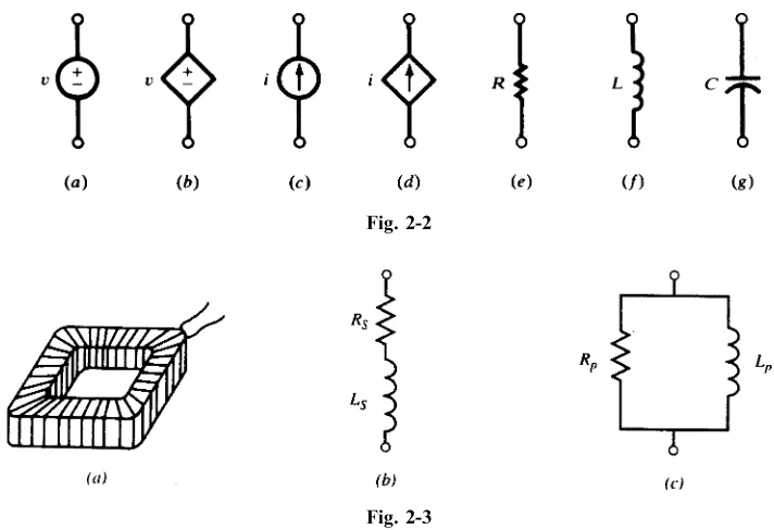
Figure 2-2 illustrates seven basic circuit elements. Elements (a) and (b) are voltage sources and (c) and (d) are current sources. A voltage source that is not affected by changes in the connected circuit is an
independentsource, illustrated by the circle in Fig. 2-2(a). Adependentvoltage source which changes in some described manner with the conditions on the connected circuit is shown by the diamond-shaped symbol in Fig. 2-2(b). Current sources may also be either independent or dependent and the correspond-ing symbols are shown in (c) and (d). The three passive circuit elements are shown in Fig. 2-2(e), (f), and (g).
The circuit diagrams presented here are termedlumped-parametercircuits, since a single element in one location is used to represent a distributed resistance, inductance, or capacitance. For example, a coil consisting of a large number of turns of insulated wire has resistance throughout the entire length of the wire. Nevertheless, a single resistance lumped at one place as in Fig. 2-3(b) or (c) represents the dis-tributed resistance. The inductance is likewise lumped at one place, either in series with the resistance as in (b) or in parallel as in (c).
Fig. 2-1
In general, a coil can be represented by either a series or a parallel arrangement of circuit elements. The frequency of the applied voltage may require that one or the other be used to represent the device.
2.2 SIGN CONVENTIONS
A voltage function and a polarity must be specified to completely describe a voltage source. The polarity marks,þand, are placed near the conductors of the symbol that identifies the voltage source. If, for example,v¼10:0 sin!tin Fig. 2-4(a), terminalAis positive with respect toBfor 0> !t> , and Bis positive with respect toAfor > !t>2for the first cycle of the sine function.
Similarly, a current source requires that a direction be indicated, as well as the function, as shown in Fig. 2-4(b). For passive circuit elementsR,L, andC, shown in Fig. 2-4(c), the terminal where the current enters is generally treated as positive with respect to the terminal where the current leaves.
The sign on power is illustrated by the dc circuit of Fig. 2-5(a) with constant voltage sources VA¼20:0 V andVB¼5:0 V and a single 5-resistor. The resulting current of 3.0 A is in the clockwise direction. Considering now Fig. 2-5(b), power is absorbed by an element when the current enters the element at the positive terminal. Power, computed by VI or I2R, is therefore absorbed by both the resistor and the VB source, 45.0 W and 15 W respectively. Since the current enters VA at the negative terminal, this element is the power source for the circuit. P¼VI ¼60:0 W confirms that the power absorbed by the resistor and the sourceVB is provided by the sourceVA.
Fig. 2-2
Fig. 2-3
2.3 VOLTAGE-CURRENT RELATIONS
The passive circuit elements resistance R, inductance L, and capacitance C are defined by the manner in which the voltage and current are related for the individual element. For example, if the voltagev and currenti for a single element are related by a constant, then the element is a resistance, Ris the constant of proportionality, and v¼Ri. Similarly, if the voltage is the time derivative of the current, then the element is an inductance, L is the constant of proportionality, and v¼L di=dt. Finally, if the current in the element is the time derivative of the voltage, then the element is a capacitance, C is the constant of proportionality, and i¼C dv=dt. Table 2-1 summarizes these rela-tionships for the three passive circuit elements. Note the current directions and the corresponding polarity of the voltages.
Fig. 2-5
Table 2-1
Circuit element Units Voltage Current Power
Resistance
ohms () v¼Ri (Ohms’s law)
i¼ v
R p¼vi¼i 2R
Inductance
henries (H) v¼Ldi
dt i¼ 1 L ð
v dtþk1 p¼vi¼Li di dt
Capacitance
farads (F) v¼ 1 C ð
i dtþk2 i¼C dv
2.4 RESISTANCE
All electrical devices that consume energy must have a resistor (also called a resistance) in their circuit model. Inductors and capacitors may store energy but over time return that energy to the source or to another circuit element. Power in the resistor, given byp¼vi¼i2R¼v2=R, is always positive as illustrated in Example 2.1 below. Energy is then determined as the integral of the instantaneous power
w¼ ðt2
t1
p dt¼R ðt2
t1
i2dt¼1 R
ðt2
t1 v2dt
EXAMPLE 2.1. A 4.0-resistor has a currenti¼2:5 sin!t (A). Find the voltage, power, and energy over one cycle. !¼500 rad/s.
v¼Ri¼10:0 sin!tðVÞ
p¼vi¼i2R¼25:0 sin2!tðWÞ
w¼ ðt
0
p dt¼25:0 t 2
sin 2!t 4!
ðJÞ
The plots ofi,p, and wshown in Fig. 2-6 illustrate thatpis always positive and that the energyw, although a function of time, is always increasing. This is the energy absorbed by the resistor.
2.5 INDUCTANCE
The circuit element that stores energy in a magnetic field is an inductor (also called aninductance). With time-variable current, the energy is generally stored during some parts of the cycle and then returned to the source during others. When the inductance is removed from the source, the magnetic field will collapse; in other words, no energy is stored without a connected source. Coils found in electric motors, transformers, and similar devices can be expected to have inductances in their circuit models. Even a set of parallel conductors exhibits inductance that must be considered at most frequencies. The power and energy relationships are as follows.
p¼vi¼Ldi dti¼
d dt
1 2 Li
2
wL¼ ðt2
t1 p dt¼
ðt2
t1
Li dt¼1 2L½i
2 2i21
Energy stored in the magnetic field of an inductance iswL¼12Li 2
.
EXAMPLE 2.2. In the interval 0>t>ð=50Þs a 30-mH inductance has a currenti¼10:0 sin 50t(A). Obtain the voltage, power, and energy for the inductance.
v¼Ldi
dt¼15:0 cos 50tðVÞ p¼vi¼75:0 sin 100tðWÞ wL¼ ðt
0
p dt¼0:75ð1cos 100tÞ ðJÞ
As shown in Fig. 2-7, the energy is zero att¼0 andt¼ ð=50Þs. Thus, while energy transfer did occur over the interval, this energy was first stored and later returned to the source.
2.6 CAPACITANCE
The circuit element that stores energy in an electric field is a capacitor (also called capacitance). When the voltage is variable over a cycle, energy will be stored during one part of the cycle and returned in the next. While an inductance cannot retain energy after removal of the source because the magnetic field collapses, the capacitor retains the charge and the electric field can remain after the source is removed. This charged condition can remain until a discharge path is provided, at which time the energy is released. The charge, q¼Cv, on a capacitor results in an electric field in the dielectric which is the mechanism of the energy storage. In the simple parallel-plate capacitor there is an excess of charge on one plate and a deficiency on the other. It is the equalization of these charges that takes place when the capacitor is discharged. The power and energy relationships for the capa-citance are as follows.
p¼vi¼Cvdv dt¼
d dt
1 2 Cv
2
wC¼ ðt2
t1 p dt¼
ðt2
t1
Cv dv¼1 2C½v
2 2v21
The energy stored in the electric field of capacitance iswC¼12Cv 2
.
EXAMPLE 2.3. In the interval 0>t>5ms, a 20-mF capacitance has a voltagev¼50:0 sin 200t(V). Obtain the charge, power, and energy. PlotwCassumingw¼0 att¼0.
q¼Cv¼1000 sin 200tðmCÞ
i¼Cdv
dt¼0:20 cos 200tðAÞ p¼vi¼5:0 sin 400tðWÞ
wC¼ ðt2
t1
p dt¼12:5½1cos 400t ðmJÞ
In the interval 0>t>2:5ms the voltage and charge increase from zero to 50.0 V and 1000mC, respectively. Figure 2-8 shows that the stored energy increases to a value of 25 mJ, after which it returns to zero as the energy is returned to the source.
2.7 CIRCUIT DIAGRAMS
Every circuit diagram can be constructed in a variety of ways which may look different but are in fact identical. The diagram presented in a problem may not suggest the best of several methods of solution. Consequently, a diagram should be examined before a solution is started and redrawn if necessary to show more clearly how the elements are interconnected. An extreme example is illustrated in Fig. 2-9, where the three circuits are actually identical. In Fig. 2-9(a) the three ‘‘junctions’’ labeledA
are shown as two ‘‘junctions’’ in (b). However, resistor R4 is bypassed by a short circuit and may be removed for purposes of analysis. Then, in Fig. 2-9(c) the single junction A is shown with its three meeting branches.
2.8 NONLINEAR RESISTORS
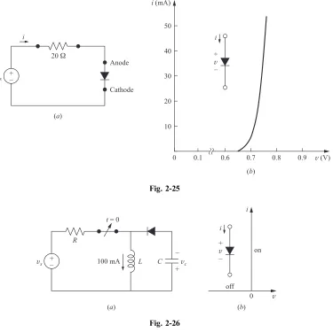
The current-voltage relationship in an element may be instantaneous but not necessarily linear. The element is then modeled as a nonlinear resistor. An example is a filament lamp which at higher voltages draws proportionally less current. Another important electrical device modeled as a nonlinear resistor is a diode. A diode is a two-terminal device that, roughly speaking, conducts electric current in one direction (from anode to cathode, called forward-biased) much better than the opposite direction (reverse-biased). The circuit symbol for the diode and an example of its current-voltage characteristic are shown in Fig. 2-25. The arrow is from the anode to the cathode and indicates the forward direction ði>0Þ. A small positive voltage at the diode’s terminal biases the diode in the forward direction and can produce a large current. A negative voltage biases the diode in the reverse direction and produces little current even at large voltage values. An ideal diode is a circuit model which works like a perfect switch. See Fig. 2-26. Itsði;vÞcharacteristic is
v¼0 wheni0 i¼0 whenv0
Thestatic resistanceof a nonlinear resistor operating atðI;VÞisR¼V=I. Itsdynamic resistanceis r¼V=I which is the inverse of the slope of the current plotted versus voltage. Static and dynamic resistances both depend on the operating point.
EXAMPLE 2.4. The current and voltage characteristic of a semiconductor diode in the forward direction is measured and recorded in the following table:
v(V) 0.5 0.6 0.65 0.66 0.67 0.68 0.69 0.70 0.71 0.72 0.73 0.74 0.75
i(mA) 2104 0.11 0.78 1.2 1.7 2.6 3.9 5.8 8.6 12.9 19.2 28.7 42.7
In the reverse direction (i.e., when v<0), i¼41015 A. Using the values given in the table, calculate the static and dynamic resistances (R and r) of the diode when it operates at 30 mA, and find its power consumptionp.
From the table
R¼V I
0:74
28:7103¼25:78
r¼V I
0:750:73
ð42:719:2Þ 103¼0:85 p¼VI 0:7428:7103W¼21:238 mW
EXAMPLE 2.5. The current and voltage characteristic of a tungsten filament light bulb is measured and recorded in the following table. Voltages are DC steady-state values, applied for a long enough time for the lamp to reach thermal equilibrium.
v(V) 0.5 1 1.5 2 3 3.5 4 4.5 5 5.5 6 6.5 7 7.5 8
i(mA) 4 6 8 9 11 12 13 14 15 16 17 18 18 19 20
Find the static and dynamic resistances of the filament and also the power consumption at the operating points (a) i¼10 mA; (b) i¼15 mA.
R¼V
I ; r¼ V
I; p¼VI
ðaÞ R 2:5
10103¼250;r
32
ð119Þ 103¼500;p2:51010
3W¼25 mW
ðbÞ R 5
15103¼333;r
5:54:5
ð1614Þ 103¼500;p51510
3W¼75 mW
Solved Problems
2.1 A 25.0-resistance has a voltage v¼150:0 sin 377t(V). Find the corresponding current i and powerp.
i¼ v
R¼6:0 sin 377tðAÞ p¼vi¼900:0 sin
2377tðWÞ
2.2 The current in a 5-resistor increases linearly from zero to 10 A in 2 ms. At t¼2þ ms the current is again zero, and it increases linearly to 10 A att¼4 ms. This pattern repeats each 2 ms. Sketch the correspondingv.
Sincev¼Ri, the maximum voltage must beð5Þð10Þ ¼50 V. In Fig. 2-10 the plots ofiandvare shown. The identical nature of the functions is evident.
2.3 An inductance of 2.0 mH has a currenti¼5:0ð1e5000tÞ(A). Find the corresponding voltage and the maximum stored energy.
v¼Ldi dt¼50:0e
5000tðVÞ
In Fig. 2-11 the plots ofiandvare given. Since the maximum current is 5.0 A, the maximum stored energy is
Wmax¼ 1 2LI
2
2.4 An inductance of 3.0 mH has a voltage that is described as follows: for 0>t>2 ms,V¼15:0 V and, for 2>t>4 ms,V¼ 30:0 V. Obtain the corresponding current and sketchvLandifor the given intervals.
For 0>t>2 ms,
i¼1 L
ðt
0
v dt¼ 1 3103
ðt
0
15:0dt¼5103tðAÞ
Fort¼2 ms,
i¼10:0 A
For 2>t>4 ms,
i¼1 L
ðt
2103
v dtþ10:0þ 1 3103
ðt
2103
30:0dt
¼10:0þ 1
3103½30:0tþ ð60:010 3Þ ðAÞ
¼30:0 ð10103tÞ ðAÞ
See Fig. 2-12.
2.5 A capacitance of 60.0mF has a voltage described as follows: 0>t>2 ms, v¼25:0103t (V).
Sketchi,p, andwfor the given interval and findWmax.
For 0>t>2 ms,
Fig. 2-10
i¼Cdv
dt¼6010
6 d
dtð25:010 3
tÞ ¼1:5 A
p¼vi¼37:5103tðWÞ
wC¼ ðt
0
p dt¼1:875104t2ðmJÞ
See Fig. 2-13.
Wmax¼ ð1:875104Þð2103Þ2¼75:0 mJ
Wmax¼1 2CV
2 max¼
1
2ð60:010
6Þð50:0Þ2¼75:0 mJ or
2.6 A 20.0-mF capacitance is linearly charged from 0 to 400mC in 5.0 ms. Find the voltage function
andWmax.
q¼ 40010 6
5:0103 !
t¼8:0102tðCÞ
v¼q=C¼4:0103tðVÞ
Vmax¼ ð4:0103Þð5:0103Þ ¼20:0 V Wmax¼ 1 2CV
2
max¼4:0 mJ
2.7 A series circuit withR¼2,L¼2 mH, andC¼500mF has a current which increases linearly
from zero to 10 A in the interval 0t1 ms, remains at 10 A for 1 mst2 ms, and decreases linearly from 10 A att¼2 ms to zero att¼3 ms. SketchvR,vL, andvC.
vRmust be a time function identical toi, withVmax¼2ð10Þ ¼20 V. For 0<t<1 ms,
di
dt¼1010
3A=s and v
L¼L
di dt¼20 V
Whendi=dt¼0, for 1 ms<t<2 ms,vL¼0. Fig. 2-12
Assuming zero initial charge on the capacitor,
vC¼ 1 C ð
i dt
For 0t1 ms,
vC¼ 1 5104
ðt
0
104t dt¼107t2ðVÞ
This voltage reaches a value of 10 V at 1 ms. For 1 ms<t<2 ms,
vC¼ ð20103Þðt103Þ þ10ðVÞ
See Fig. 2-14.
2.8 A single circuit element has the current and voltage functions graphed in Fig. 2-15. Determine the element.
Fig. 2-14
The element cannot be a resistor since v andi are not proportional. v is an integral of i. For 2 ms<t<4 ms,i6¼0 butvis constant (zero); hence the element cannot be a capacitor. For 0<t<2 ms,
di
dt¼510
3A=s and v¼15 V
Consequently,
L¼v
di dt¼3 mH
(Examine the interval 4 ms<t<6 ms;Lmust be the same.)
2.9 Obtain the voltage v in the branch shown in Fig. 2-16 for (a) i2¼1 A, (b) i2¼ 2 A, (c) i2¼0 A.
Voltagevis the sum of the current-independent 10-V source and the current-dependent voltage source vx. Note that the factor 15 multiplying the control current carries the units.
v¼10þvx¼10þ15ð1Þ ¼25 V ðaÞ
v¼10þvx¼10þ15ð2Þ ¼ 20 V ðbÞ
v¼10þ15ð0Þ ¼10 V ðcÞ
2.10 Find the power absorbed by the generalized circuit element in Fig. 2-17, for (a) v¼50 V, (b) v¼ 50 V.
Since the current enters the element at the negative terminal,
p¼ vi¼ ð50Þð8:5Þ ¼ 425 W ðaÞ
p¼ vi¼ ð50Þð8:5Þ ¼425 W ðbÞ
2.11 Find the power delivered by the sources in the circuit of Fig. 2-18.
i¼2050
3 ¼ 10 A
The powersabsorbedby the sources are:
Fig. 2-16
pa¼ vai¼ ð20Þð10Þ ¼200 W pb¼vbi¼ ð50Þð10Þ ¼ 500 W
Since power delivered is the negative of power absorbed, sourcevbdelivers 500 W and sourceva absorbs 200 W. The power in the two resistors is 300 W.
2.12 A 25.0-resistance has a voltagev¼150:0 sin 377t(V). Find the powerpand the average power pavg over one cycle.
i¼v=R¼6:0 sin 377tðAÞ
p¼vi¼900:0 sin2377tðWÞ
The end of one period of the voltage and current functions occurs at 377t¼2. For Pavg the integration is taken over one-half cycle, 377t¼. Thus,
Pavg¼ 1
ð
0
900:0 sin2ð377tÞdð377tÞ ¼450:0ðWÞ
2.13 Find the voltage across the 10.0-resistor in Fig. 2-19 if the control currentixin the dependent source is (a) 2 A and (b) 1 A.
i¼4ix4:0; vR¼iR¼40:0ix40:0ðVÞ ix¼2; vR¼40:0 V
ix¼ 1; vR¼ 80:0 V
Supplementary Problems
2.14 A resistor has a voltage ofV¼1:5 mV. Obtain the current if the power absorbed is (a) 27.75 nW and (b) 1.20mW. Ans. 18.5mA, 0.8 mA
Fig. 2-18
2.15 A resistance of 5.0has a currenti¼5:0103t(A) in the interval 0t2 ms. Obtain the instantaneous and average power. Ans. 125.0t2(W), 167.0 (W)
2.16 Currentienters a generalized circuit element at the positive terminal and the voltage across the element is 3.91 V. If the powerabsorbedis25:0 mW, obtain the current. Ans. 6:4 mA
2.17 Determine the single circuit element for which the current and voltage in the interval 0103tare given byi¼2:0 sin 103t(mA) andv¼5:0 cos 103t(mV). Ans. An inductance of 2.5 mH
2.18 An inductance of 4.0 mH has a voltagev¼2:0e103t(V). Obtain the maximum stored energy. Att¼0, the current is zero. Ans. 0.5 mW
2.19 A capacitance of 2.0mF with an initial charge Q0 is switched into a series circuit consisting of a 10.0-resistance. FindQ0if the energy dissipated in the resistance is 3.6 mJ. Ans. 120.0mC
2.20 Given that a capactance ofCfarads has a current i¼ ðVm=RÞet=ðRcÞ(A), show that the maximum stored energy is1
2CV 2
m. Assume the initial charge is zero.
2.21 The current aftert¼0 in a single circuit element is as shown in Fig. 2-20. Find the voltage across the element att¼6:5ms, if the element is (a) 10 k, (b) 15 mH, (c) 0.3 nF withQð0Þ ¼0.
Ans. (a) 25 V; (b) 75 V; (c) 81.3 V
2.22 The 20.0-mF capacitor in the circuit shown in Fig. 2-21 has a voltage fort>0,v¼100:0et=0:015(V). Obtain the energy function that accompanies the discharge of the capacitor and compare the total energy to that which is absorbed by the 750-resistor. Ans. 0.10ð1et=0:0075Þ(J)
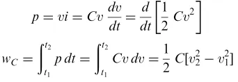
2.23 Find the currentiin the circuit shown in Fig. 2-22, if the controlv2of the dependent voltage source has the value (a) 4 V, (b) 5 V, (c) 10 V. Ans. (a) 1 A; (b) 0 A; (c) 5 A
2.24 In the circuit shown in Fig. 2-23, find the current, i, given (a) i1¼2 A, i2¼0; (b) i1¼ 1 A;i2¼4 A; (c) i1¼i2¼1 A. Ans. (a) 10 A; (b) 11 A; (c) 9A
2.25 A 1-mF capacitor with an initial charge of 104C is connected to a resistor R att¼0. Assume discharge current during 0<t<1 ms is constant. Approximate the capacitor voltage drop at t¼1 ms for
Fig. 2-20
(a) R¼1M; (b) R¼100k; (c) R¼10k. Hint: Compute the charge lost during the 1-ms period. Ans. (a) 0.1 V; (b) 1 V; (b) 10 V
2.26 The actual discharge current in Problem 2.25 isi¼ ð100=RÞe106t=RA. Find the capacitor voltage drop at 1 ms after connection to the resistor for (a) R¼1M; (b) R¼100k; (c) R¼10k.
Ans. (a) 0.1 V; (b) 1 V; (c) 9.52 V
2.27 A 10-mF capacitor discharges in an element such that its voltage isv¼2e1000t. Find the current and power delivered by the capacitor as functions of time.
Ans. i¼20e1000tmA,p¼vi¼40e1000tmJ
2.28 Find voltagev, currenti, and energyWin the capacitor of Problem 2.27 at timet¼0, 1, 3, 5, and 10 ms. By integrating the power delivered by the capacitor, show that the energy dissipated in the element during the interval from 0 totis equal to the energy lost by the capacitor.
t v i W
0 2 V 20 mA 20mJ
1 ms 736 mV 7.36 mA 2.7mJ
3 ms 100 mV 1 mA 0.05mJ
5 ms 13.5 mV 135mA 0:001mJ
10 ms 91mV 0.91mA 0
2.29 The current delivered by a current source is increased linearly from zero to 10 A in 1-ms time and then is decreased linearly back to zero in 2 ms. The source feeds a 3-kresistor in series with a 2-H inductor (see Fig. 2-24). (a) Find the energy dissipated in the resistor during the rise time ðW1Þ and the fall time ðW2Þ. (b) Find the energy delivered to the inductor during the above two intervals. (c) Find the energy delivered by the current source to the series RL combination during the preceding two intervals. Note: Series elements have the same current. The voltage drop across their combination is the sum of their individual voltages.
Ans. ðaÞ W1¼100;W2¼200; (b) W1¼200;W2¼ 200; (c) W1¼300;W2¼0, all in joules
2.30 The voltage of a 5-mF capacitor is increased linearly from zero to 10 V in 1 ms time and is then kept at that level. Find the current. Find the total energy delivered to the capacitor and verify that delivered energy is equal to the energy stored in the capacitor.
Ans. i¼50 mA during 0<t<1 ms and is zero elsewhere, W¼250mJ. Fig. 2-22
Fig. 2-23
2.31 A 10-mF capacitor is charged to 2 V. A path is established between its terminals which draws a constant current ofI0. (a) ForI0¼1 mA, how long does it take to reduce the capacitor voltage to 5 percent of its initial value? (b) For what value ofI0does the capacitor voltage remain above 90 percent of its initial value after passage of 24 hours?
Ans. (a) 19 ms, (b) 23.15pA
2.32 Energy gained (or lost) by an electric charge qtraveling in an electric field is qv, where v is the electric potential gained (or lost). In a capacitor with charge Q and terminal voltage V, let all charges go from one plate to the other. By way of computation, show that the total energy W gained (or lost) is notQV but QV=2 and explain why. Also note thatQV=2 is equal to the initial energy content of the capacitor. Ans. W¼Ð
qvdt¼QV0 2
¼QV=2¼1 2CV
2. The apparent discrepancy is explained by the following. The starting voltage vetween the two plates is V. As the charges migrate from one plate of the capacitor to the other plate, the voltage between the two plates drops and becomes zero when all charges have moved. The average of the voltage during the migration process isV=2, and therefore, the total energy isQV=2.
2.33 Lightning I. The time profile of the discharge current in a typical cloud-to-ground lightning stroke is modeled by a triangle. The surge takes 1ms to reach the peak value of 100 kA and then is reduced to zero in 99mS. (a) Find the electric charge Q discharged. (b) If the cloud-to-ground voltage before the discharge is 400 MV, find the total energy W released and the average power P during the discharge. (c) If during the storm there is an average of 18 such lightning strokes per hour, find the average power released in 1 hour. Ans. (a) Q¼5 C; (b) W¼109J;P¼1013W; (c) 5 MW
2.34 Lightning II. Find the cloud-to-ground capacitance in Problem 2.33 just before the lightning stroke. Ans. 12.5mF
2.35 Lightning III. The current in a cloud-to-ground lightning stroke starts at 200 kA and diminishes linearly to zero in 100ms. Find the energy released W and the capacitance of the cloud to ground C if the voltage before the discharge is (a) 100 MV; (b) 500 MV.
Ans. (a) W¼5108J;C¼0:1mF; (b) W¼25108J;C¼20 nF
2.36 The semiconductor diode of Example 2.4 is placed in the circuit of Fig. 2-25. Find the current for (a) Vs¼1 V, (b) Vs¼ 1 V. Ans. (a) 14 mA; (b) 0
2.37 The diode in the circuit of Fig. 2-26 is ideal. The inductor draws 100 mA from the voltage source. A 2-mF capacitor with zero initial charge is also connected in parallel with the inductor through an ideal diode such that the diode is reversed biased (i.e., it blocks charging of the capacitor). The switchssuddenly disconnects with the rest of the circuit, forcing the inductor current to pass through the diode and establishing 200 V at the capacitor’s terminals. Find the value of the inductor. Ans. L¼8 H
2.38 Compute the static and dynamic resistances of the diode of Example 2.4 at the operating pointv¼0:66 V.
Ans: R 0:66
1:2103¼550 and r
0:670:65
2.39 The diode of Example 2.4 operates within the range 10<i<20 mA. Within that range, approximate its terminal characteristic by a straight linei¼vþ, by specifyingand.
Ans. i¼630v4407 mA, wherevis in V
2.40 The diode of Example 2.4 operates within the range of 20<i<40 mA. Within that range, approximate its terminal characteristic by a straight line connecting the two operating limits.
Ans. i¼993:33v702:3 mA, wherevis in V
2.41 Within the operating range of 20<i<40 mA, model the diode of Example 2.4 by a resistorRin series with a voltage sourceVsuch that the model matches exactly with the diode performance at 0.72 and 0.75 V. Find RandV. Ans. R¼1:007;V¼707 mV
Fig. 2-25
24
Circuit Laws
3.1 INTRODUCTION
An electric circuit or network consists of a number of interconnected single circuit elements of the type described in Chapter 2. The circuit will generally contain at least one voltage or current source. The arrangement of elements results in a new set of constraints between the currents and voltages. These new constraints and their corresponding equations, added to the current-voltage relationships of the individual elements, provide the solution of the network.
The underlying purpose of defining the individual elements, connecting them in a network, and solving the equations is to analyze the performance of such electrical devices as motors, generators, transformers, electrical transducers, and a host of electronic devices. The solution generally answers necessary questions about the operation of the device under conditions applied by a source of energy.
3.2 KIRCHHOFF’S VOLTAGE LAW
For any closed path in a network,Kirchhoff’s voltage law(KVL) states that the algebraic sum of the voltages is zero. Some of the voltages will be sosurces, while others will result from current in passive elements creating a voltage, which is sometimes referred to as avoltage drop. The law applies equally well to circuits driven by constant sources, DC, time variable sources,vðtÞandiðtÞ, and to circuits driven
by sources which will be introduced in Chapter 9. The mesh current method of circuit analysis introduced in Section 4.2 is based on Kirchhoff’s voltage law.
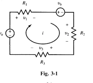
EXAMPLE 3.1. Write the KVL equation for the circuit shown in Fig. 3-1.
Fig. 3-1
Starting at the lower left corner of the circuit, for the current direction as shown, we have
vaþv1þvbþv2þv3¼0
vaþiR1þvbþiR2þiR3¼0
vavb¼iðR1þR2þR3Þ
3.3 KIRCHHOFF’S CURRENT LAW
The connection of two or more circuit elements creates a junction called anode. The junction between two elements is called asimple nodeand no division of current results. The junction of three or more elements is called aprincipal node, and here current division does take place. Kirchhoff’s current law(KCL) states that the algrebraic sum of the currents at a node is zero. It may be stated alternatively that the sum of the currents entering a node is equal to the sum of the currents leaving that node. The node voltage method of circuit analysis introduced in Section 4.3 is based on equations written at the principal nodes of a network by applying Kirchhoff’s current law. The basis for the law is the con-servation of electric charge.
EXAMPLE 3.2. Write the KCL equation for the principal node shown in Fig. 3-2. i1i2þi3i4i5¼0
i1þi3¼i2þi4þi5
3.4 CIRCUIT ELEMENTS IN SERIES
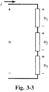
Three passive circuit elements in series connection as shown in Fig. 3-3 have the same currenti. The
voltages across the elements arev1,v2, andv3. The total voltagevis the sum of the individual voltages; v¼v1þv2þv3.
If the elements are resistors,
Fig. 3-2
v¼iR1þiR2þiR3
¼iðR1þR2þR3Þ ¼iReq
where a single equivalent resistance R
eq replaces the three series resistors. The same relationship
betweeni andvwill pertain.
For any number of resistors in series, we have R
eq ¼R1þR2þ .
If the three passive elements are inductances,
v¼L1 di dtþL2
di
dtþL3 di
dt
¼ ðL1þL2þL3Þdi dt
¼Leq di dt
Extending this to any number of inductances in series, we have Leq¼L1þL2þ .
If the three circuit elements are capacitances, assuming zero initial charges so that the constants of integration are zero,
v¼ 1 C1
ð
i dtþ 1 C2
ð
i dtþ 1 C3
ð i dt
¼ 1 C1þ
1
C2þ
1 C3 ð i dt ¼ 1 C eq ð i dt
The equivalent capacitance of several capacitances in series is 1=C
eq¼1=C1þ1=C2þ .
EXAMPLE 3.3. The equivalent resistance of three resistors in series is 750.0. Two of the resistors are 40.0 and 410.0. What must be the ohmic resistance of the third resistor?
Req¼R1þR2þR3
750:0¼40:0þ410:0þR3 and R3¼300:0
EXAMPLE 3.4. Two capacitors,C1¼2:0mF andC2¼10:0mF, are connected in series. Find the equivalent
capacitance. Repeat ifC2is 10.0 pF.
Ceq¼ C1C2 C1þC2¼
ð2:0106Þð10:0106Þ
2:0106þ10:0106¼1:67mF
IfC2¼10:0 pF,
Ceq¼ð2:010
6Þð10:01012Þ
2:0106þ10:01012¼
20:01018
2:0106 ¼10:0 pF
where the contribution of 10:01012to the sumC1þC2in the denominator is negligible and therefore it can be omitted.
Note: When two capacitors in series differ by a large amount, the equivalent capacitance is essen-tially equal to the value of the smaller of the two.
3.5 CIRCUIT ELEMENTS IN PARALLEL
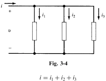
For three circuit elements connected in parallel as shown in Fig. 3-4, KCL states that the currenti
i¼i1þi2þi3
If the three passive circuit elements are resistances,
i¼ v R 1 þ v R 2 þ v R 3 ¼ 1 R 1 þ 1 R 2 þ 1 R 3
v¼ 1 R
eq v
For several resistors in parallel,
1
Req¼
1
R1þ
1
R2þ
The case of two resistors in parallel occurs frequently and deserves special mention. The equivalent resistance of two resistors in parallel is given by theproduct over the sum.
Req¼ R1R2 R1þR2
EXAMPLE 3.5. Obtain the equivalent resistance of (a) two 60.0- resistors in parallel and (b) three 60.0- resistors in parallel.
Req¼ð60:0Þ 2
120:0 ¼30:0 ðaÞ
1 Req¼
1 60:0þ
1 60:0þ
1
60:0 Req¼20:0 ðbÞ
Note: Forn identical resistors in parallel the equivalent resistance is given byR=n.
Combinations of inductances in parallel have similar expressions to those of resistors in parallel:
1
Leq¼
1
L1þ
1
L2þ and, for two inductances, Leq¼
L1L2
L1þL2
EXAMPLE 3.6. Two inductancesL1¼3:0 mH andL2¼6:0 mH are connected in parallel. FindLeq.
1 Leq¼
1 3:0 mHþ
1
6:0 mH and Leq¼2:0 mH
With three capacitances in parallel,
i¼C1 dv dtþC2
dv
dtþC3 dv
dt ¼ ðC1þC2þC3Þ dv
dt ¼Ceq dv
dt
3.6 VOLTAGE DIVISION
A set of series-connected resistors as shown in Fig. 3-5 is referred to as a voltage divider. The concept extends beyond the set of resistors illustrated here and applies equally to impedances in series, as will be shown in Chapter 9.
Sincev1¼iR1 andv¼iðR1þR2þR3Þ,
v1¼v R1 R1þR2þR3
EXAMPLE 3.7. A voltage divider circuit of two resistors is designed with a total resistance of the two resistors equal to 50.0. If the output voltage is 10 percent of the input voltage, obtain the values of the two resistors in the circuit.
v1
v ¼0:10 0:10¼ R1 50:0103
from whichR1¼5:0andR2¼45:0.
3.7 CURRENT DIVISION
A parallel arrangement of resistors as shown in Fig. 3-6 results in acurrent divider. The ratio of the branch currenti1 to the total currentiillustrates the operation of the divider.
i¼ v R1þ
v
R2þ v
R3 and i1¼ v
R1 i1
i ¼
1=R1
1=R
1þ1=R2þ1=R3
¼ R2R3 R
1R2þR1R3þR2R3
Then
Fig. 3-5
For a two-branch current divider we have
i 1 i ¼
R 2 R1þR2
This may be expressed as follows: The ratio of the current in one branch of a two-branch parallel circuit to the total current is equal to the ratio of the resistance of theotherbranch resistance to the sum of the two resistances.
EXAMPLE 3.8. A current of 30.0 mA is to be divided into two branch currents of 20.0 mA and 10.0 mA by a network with an equivalent resistance equal to or greater than 10.0. Obtain the branch resistances.
20 mA 30 mA¼
R2
R1þR2
10 mA 30 mA¼
R1
R1þR2
R1R2
R1þR210:0
Solving these equations yieldsR115:0andR230:0.
Solved Problems
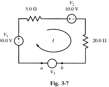
3.1 FindV3 and its polarity if the currentI in the circuit of Fig. 3-7 is 0.40 A.
Assume thatV3has the same polarity asV1. Applying KVL and starting from the lower left corner,
V1Ið5:0Þ V2Ið20:0Þ þV3¼0
50:02:010:08:0þV3¼0 V3¼ 30:0 V
Terminalbis positive with respect to terminala.
3.2 Obtain the currentsI1 andI2 for the network shown in Fig. 3-8.
aandbcomprise one node. Applying KCL,
2:0þ7:0þI1¼3:0 or I1¼ 6:0 A
Also,canddcomprise a single node. Thus,
4:0þ6:0¼I2þ1:0 or I2¼9:0 A
The branch currents within the enclosed area cannot be calculated since no values of the resistors are given. However, KCL applies to the network taken as a single node. Thus,
2:03:04:0I¼0 or I¼ 5:0 A
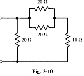
3.4 Find the equivalent resistance for the circuit shown in Fig. 3-10.
The two 20-resistors in parallel have an equivalent resistanceReq¼ ½ð20Þð20Þ=ð20þ20Þ ¼10. This is in series with the 10-resistor so that their sum is 20. This in turn is in parallel with the other 20- resistor so that the overall equivalent resistance is 10.
3.5 Determine the equivalent inductance of the three parallel inductances shown in Fig. 3-11.
Fig. 3-8
Fig. 3-9
The two 20-mH inductances have an equivalent inductance of 10 mH. Since this is in parallel with the 10-mH inductance, the overall equivalent inductance is 5 mH. Alternatively,
1 Leq¼
1 L1þ
1 L2þ
1 L3¼
1 10 mHþ
1 20 mHþ
1 20 mH¼
4
20 mH or Leq¼5 mH
3.6 Express the total capacitance of the three capacitors in Fig. 3-12.
ForC2andC3in parallel,Ceq¼C2þC3. Then forC1andCeq in series,
CT ¼ C1Ceq C1þCeq¼
C1ðC2þC3Þ
C1þC2þC3
3.7 The circuit shown in Fig. 3-13 is a voltage divider, also called anattenuator. When it is a single resistor with an adjustable tap, it is called a potentiometer, or pot. To discover the effect of loading, which is caused by the resistanceRof the voltmeter VM, calculate the ratioVout=Vinfor
(a) R¼ 1, (b) 1 M, (c) 10 k, (d) 1 k.
Vout=Vin¼ 250
2250þ250¼0:100 ðaÞ
Fig. 3-11
Fig. 3-12
(b) The resistanceRin parallel with the 250-resistor has an equivalent resistance
Req¼ 250ð10 6Þ
250þ106¼249:9 and Vout=Vin¼
249:9
2250þ249:9¼0:100
Req¼ð250Þð10 000Þ
250þ10 000¼243:9 and Vout=Vin¼0:098 ðcÞ
Req¼ð250Þð1000Þ
250þ1000¼200:0 and Vout=Vin¼0:082 ðdÞ
3.8 Find all branch currents in the network shown in Fig. 3-14(a).
The equivalent resistances to the left and right of nodesaandbare
ReqðleftÞ¼5þð12Þð8Þ 20 ¼9:8
ReqðrightÞ¼ð6Þð3Þ 9 ¼2:0
Now referring to the reduced network of Fig. 3-14(b),
I3¼ 2:0
11:8ð13:7Þ ¼2:32 A
I4¼ 9:8
11:8ð13:7Þ ¼11:38 A
Then referring to the original network,
I1¼ 8
20ð2:32Þ ¼0:93 A I2¼2:320:93¼1:39 A
I5¼3
9ð11:38Þ ¼3:79 A I6¼11:383:79¼7:59 A
Supplementary Problems
3.9 Find the source voltage V and its polarity in the circuit shown in Fig. 3-15 if (a) I¼2:0 A and (b) I¼ 2:0 A. Ans. (a) 50 V,bpositive; (b) 10 V,apositive.
3.10 FindReqfor the circuit of Fig. 3-16 for (a) Rx¼ 1, (b) Rx¼0, (c) Rx¼5. Ans. (a) 36; (b) 16; (c) 20
3.11 An inductance of 8.0 mH is in series with two inductances in parallel, one of 3.0 mH and the other 6.0 mH. FindLeq. Ans. 10.0 mH
3.12 Show that for the three capacitances of equal value shown in Fig. 3-17Ceq¼1:5 C:
3.13 Find RH and RO for the voltage divider in Fig. 3-18 so that the current I is limited to 0.5 A when VO¼100 V. Ans: RH¼2 M;RO¼200
3.14 Using voltage division, calculateV1andV2in the network shown in Fig. 3-19. Ans. 11.4 V, 73.1 V
3.15 Obtain the source currentI and the total power delivered to the circuit in Fig. 3-20. Ans. 6.0 A, 228 W
3.16 Show that for four resistors in parallel the current in one branch, for example the branch ofR4, is related to the total current by
I4¼IT R
0
R4þR0
whereR0¼ R1R2R3 R1R2þR1R3þR2R3 Fig. 3-15
Fig. 3-16
Fig. 3-17
Fig. 3-18
Fig. 3-19
Note: This is similar to the case of current division in a two-branch parallel circuit where the other resistor has been replaced byR0.
3.17 A power transmission line carries current from a 6000-V generator to three loads, A, B, and C. The loads are located at 4, 7, and 10 km from the generator and draw 50, 20, and 100 A, respectively. The resistance of the line is 0.1/km; see Fig. 3-21. (a) Find the voltage at loads A, B, C. (b) Find the maximum percentage voltage drop from the generator to a load.
Ans. (a) vA¼5928 V;vB¼5889 V;vC¼5859 V; (b) 2.35 percent
3.18 In the circuit of Fig. 3-22,R¼0 andi1andi2are unknown. FindiandvAC. Ans. i¼4 A;vAC¼24 V
3.19 In the circuit of Fig. 3-22,R¼1andi1¼2 A. Find,i,i2, andvAC. Ans. i¼5 A;i2¼ 16 A;vAC¼27 V
3.20 In the circuit of Fig. 3-23, is1¼vs2¼0, vs1¼9 V, is2¼12 A. For the four cases of (a) R¼0, (b) R¼6, (c) R¼9, and (d) R¼10 000, draw the simplified circuit and find iBA and vAC. Hint: A zero voltage source corresponds to a short-circuited element and a zero current source corresponds to an open-circuited element.
Ans:
ðaÞ iBA¼7;vAC¼30 ðbÞ iBA¼4:2;vAC¼21:6 ðcÞ iBA¼3:5;vAC¼19:5
ðdÞ iBA¼0:0060;vAC¼9:029
8 > > > <
> > > :
ðAll in A and V)
3.21 In the circuit of Fig. 3-23, vs1¼vs2¼0;is1¼6 A;is2¼12 A: For the four cases of (a) R¼0;ðbÞR¼6;ðcÞR¼9;andðdÞR¼10 000;draw the simplified circuit and findiBA andvAC.
Ans:
ðaÞ iBA¼6;vAC¼36 ðbÞ iBA¼3:6;vAC¼28:8
ðcÞ iBA¼3;vAC¼27 ðdÞ iBA¼0:0050;vAC18
8 > > > <
> > > :
ðAll in A and V) Fig. 3-21
3.22 In the circuit Fig. 3-23, vs1¼0, vs2¼6 V, is1¼6 A, is2¼12 A. For the four cases of (a) R¼0, (b) R¼6, (c) R¼9, and (d) R¼10 000, draw the