DEVELOPMENT OF DYNAMIC EVOLUTION CONTROL FOR PV
INVERTER IN SOLAR POWER PLANT APPLICATION
A. S. Samosir, A. Trisantoand A. Sadnowo
Department of Electrical Engineering, University of Lampung, Bandar Lampung, Indonesia E-Mail: [email protected]
ABSTRACT
Power inverter is a kind of power electronic converter that used to convert a dc input voltage to an ac output voltage. In solar power plant application, the PV inverter converts the dc voltage from Solar PV panel, which is usually stored in the battery, into an ac output voltage to serve the load of household appliances, such as lighting, television, mobile charger, even a washing machine and water pump. Therefore, a reliable inverter that can produce a good output voltage is necessary.The main purpose of this paper is to design and develop a dynamic evolution control (DEC) for a PV Inverter in solar power plant application. The analysis and design of the DEC control technique are provided. The performance of the PV inverter controller is verified through MATLAB Simulink. To validate the simulation results, an experimental prototype of PV inverter is developed. The controller of the PV inverter system was implemented based on dynamic evolution control. The performance of the proposed dynamic evolution control is tested through simulation and experiment.
Keywords: dynamic evolution control, inverter controller, PV inverter, solar power plant.
INTRODUCTION
The increasing of world demand for energy resources is a crucial challenge that makes renewable energy sources has gained importance. One of the most promising renewable energy sources is solar photovoltaic [1]. It can produce direct current electricity when exposed to direct sunlight. Solar photovoltaic are solid state devices that convert the energy of sunlight directly into electrical energy. Solar photovoltaic have several advantages such as pollution-free, low maintenance costs and low operating costs [1-4]. Their sources of energy, which is derived from solar energy, are also widely available and it is free.
Photovoltaic technology is a technology for generating electrical power by converting solar radiation into direct current electricity using semiconductors who have photovoltaic effect. The main component of a PV system is the solar cell, which functions to convert solar energy into direct current electrical energy. When exposed to sunlight; the solar panels will generate the direct current electricity, which is ready to supply power to the load. Because of its energy conversion systems using Photovoltaic technology, the power plant of this type is also called Solar Photovoltaic Power Plant.
The commonly usedsolar PV power plant system is shown in Figure-1. The solar PV power plant system consist of Solar PV Panel, Solar charge controller, energy storage element, and PV Inverter.
In this system, the PV inverter converts the dc voltage from Solar PV panel, which is stored in the battery, into an AC output voltage to supply the AC load, such as lighting, television, mobile charger, even a washing machine and water pump. Hence, a reliable inverter that can produce a good output voltage is necessary.
Figure-1. Solar PV power plant system.
In this paper, a Dynamic Evolution Control for PV Inverter is developed. The design and performance analysisof the controller is executed under MATLAB Simulink software. The performance of PV Inverter was tested by considering the effect of load variation. Finaly, the PV inverter hardware was made to validate the effectiveness of the controller.
SOLAR PHOTOVOLTAIC MATEMATICALMODEL
In solar power plant application, several solar cells connected in series and parallel to form a solar module, and several solar modules can be connected in series or parallel to form a Solar Array in order to increase the output power of a solar panel system.
Figure-2. Solar cell equivalent circuit.
The shunt resistor current is calculated by:
sh
where Rsh = shunt resistance (Ω), and the voltage
across Rsh is Vshwhich isequal to diode voltage,VD.
Since the diode voltage is
D pv
+
pv sV
V
I R
So, the shunt resistor current can be written as:
pv pv s
Figure-3. Schemathic of full-bridge inverter.
By substituting equation (2), (3) and (4) into equation (1), the obtained characteristic equation of a solar cell that relates the output current and output voltage can be written as: converter that used to convert a dc input voltage to an ac output voltage. Power Inverter is the most important device use in many power conversions, such as dc to ac in Uninterrupted Power Supply (UPS), lighting, power quality conditioner, motor drives control, renewable energy systems, HVDC power transmission, renewable energy systems and induction heating.
In many applications, load demand varies with time, therefore the inverter should be able to provide this demand with a high quality stable ac voltage.A typical power inverter requires a relatively stable DC power source capableof supplying enough current for the intended power demands of the system.
In the last few decades, many topology inverters have been used to apply power inverters, such as full bridge, half bridge and push pull.The most commonly used inverter circuit is a full bridge inverter. The typical schematic of full bridge inverter circuit shown in Figure-3. The full-bridge inverter is widely employed in various applications. To get a high-quality output with low total harmonic distortion, sinusoidal pulse width modulation (PWM) methods are commonly used in a full-bridge inverter. Switching schemes, unipolar PWM and bipolar PWM, are well known and widely employed. In these techniques, the switches are commutated at high frequency, i.e., the frequency of the carrier signal [9-10].
pure sinewave inverter output. Three types of inverter output waveform are shown in Figure-4.
Figure-4. Inverter output waveform.
MODEL OF POWER INVERTER
Power inverter is used to convert a DC input voltage source to an AC output voltage. Here, a single phase fullbridge inverter wit LC Filter is used.
Single phase Fulbridge inverter wit LC Filter scheme is depicted as Figure-5.
Figure-5. Fullbridge inverter with LC filter.
The operation condition of Full-bridge inverter can be divided to two conditions as follows:
State 1. Switch S1 and S4are on,whileswitch S2and S3are off. In this state the voltage equation of inverter can write written as:
V
L+
Vo
inverter can write written as:in
By divided (10) with the switching period T, thus the dynamic equation of single phaseFullbridge inverter is obtained as follows:
duty cycle, iL is inductor current, VOis output voltage, L is
inductor inductance. methodfor power electronic converter.This control method has been used in many reference in recend year.The dynamic evolution control force the error state in the system to follow a specific path that ensure the error state goes to zero in increase of time. The specific path is called the dynamicevolution path [11-13].
Here, the dynamic characteristic of system is forced to do evolution by following an evolution path. When the selected evolution path is an exponential function as shown in Figure-6, the value of the dynamic characteristic of system will decrease exponentially to zero by equation
O
Y=Y .
mte
(13)where, Y is the dynamic characteristic of system, YO is the initial value of Y, and m is a design parameter specifying the rate of evolution.
0,
dY
mY
dt
m
0
(14)In order to obtain the control law that guarantees the dynamic characteristic of system decreased to zero by following the evolution path, the synthesis process should be done. In power inverter, the correspondingcontrol law is the duty cycle equation of the inverter.
The duty cycle D(Vo, Vin, iL) represents D as a function of the state Vo, Vin and iL. The duty cycle equation D(Vo, Vin, iL) Is obtained by analyzed and substituted the dynamic equation of the inverter system into the dynamic evolution function (14).
Figure-6. Dynamic evolution path.
POWER INVERTER CONTROLLER SYNTHESIS
The dynamic evolution synthesis of the controller begins by defining the state error function (Y) as
Y=k.
V
err (15)Where k is a positive coefficient and Verr is error voltage.
Substitution (15) and (16) into (14), yields
k.
err. .
0
Directly substituting the inverter voltage output Vo from (12) into (18) we get:
Solving for D, the obtained duty cycle is given by:
2
Table-1. Specification of solar world SW50 module [14].
Parameters Symbol Value
Maximum power Pm 50 W
The duty cycle equation (20) forces the state error (Y=k. Verr) to satisfy the dynamic evolution function (9).Consequently, the state error (Y) is forced to make evolution by following (8) and decrease to zero (Y =0) with a decrease rate m. Hence, the state error function (Y) satisfy the equation
Y=k.
V
err
0
Thus the state error of the inverter will converge to zero.
Solar power plant simulation result
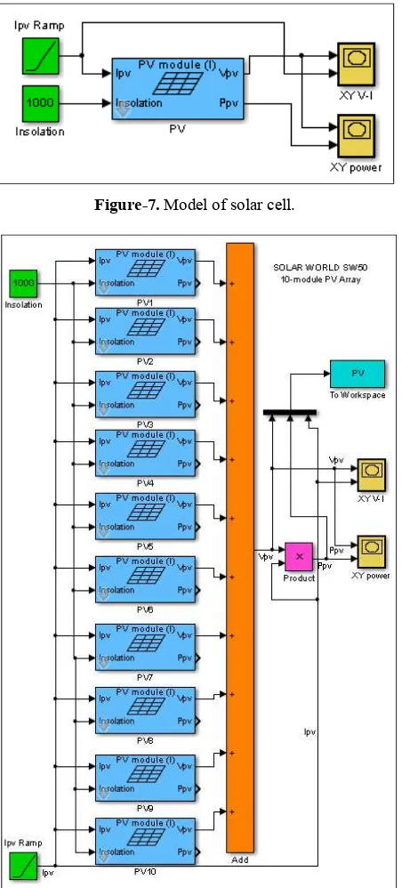
of the Solar Cell was implemented in MATLAB-Simulink software. Specification of Solar World SW50 Module is presented in Table-1. Figure-7 shows the model of the Solar Cell with input parameters irradiance and voltage.
The Solar PV Panel model was developed using 10-modules Solar Cell in series connection. The developed model of the Solar PV Panelis shown as Figure-8. The performance of Solar PVPanel model is tested through simulation. Figure 9 shows the Current-Voltagecurve and Figure 10 shows the Power-Voltage curve of the Solar PV Panel.
Figure-7. Model of solar cell.
Figure-8. Model of solar PV panel.
Figure-9. Current-voltage curve of solar PV panel.
Figure-10. Power-voltage curve of solar PV panel.
PV inverter simulation result
Power Inverter scheme and the dynamic evolution control equation, which is described by (15), are modeled in Simulink as shown in Figure-11. Model parameters are listed in Table-2. The control goal is to produce120V, 60 Hz sinusoidal output voltage. The reference of the output voltage is specified based on the desired output voltage.
120 2 sin120
refV
t
(22)Figures 12 and 13 show the result for steady-state performance of the proposed dynamic evolution control for no-load and full-load condition. The results give a satisfactory performance which indicates that the proposed dynamic evolution control is capable to avoid voltage output level from dropping when a load is connected.
0 20 40 60 80 100 120 140 160 180 200 220 240
0 1 2 3 4 5 6
Voltage (V)
Cu
rren
t (
A
)
0 20 40 60 80 100 120 140 160 180 200 220 240 0
100 200 300 400 500 600 700 800 900
Voltage (V)
Po
w
er
(W
Figure-11. Power inverter simulation model.
Figure-12. Steady-state performance (no-load).
Figure-13. Steady-state performance (full-load).
Experiment results
To validate the effectiveness of dynamic evolution control technique, a hardware prototype of fullbridge inverter was built as shown in Figure-14. Power Inverter part wasbuilt using four of power IGBT HGTG20N60B3D, and the gate driver circuit was built using HCPL 3120.
A DSP based dynamic evolution controller has been implemented. The DSP Board TMS320F2812is employed to implement the dynamic evolution control and the PWM signal generator. The experiment results are shown in Figures 15 and 16.
Figure-14. Hardware prototype of inverter system.
Figure-15. Output voltage when no load condition.
Figure-16. One cycle output voltage.
CONCLUSIONS
This paper presents a dynamic evolution control 0 0.002 0.004 0.006 0.008 0.01 0.012 0.014 0.016
-200 -150 -100 -50 0 50 100 150 200
Output Voltage
Output Current
0 0.002 0.004 0.006 0.008 0.01 0.012 0.014 0.016 -200
-150 -100 -50 0 50 100 150 200
control has been investigated under simulation and experiment test. The results show the dynamic evolution control accomplishes to produce120V, 60 Hz sinusoidal output voltage, and regulate the PV Inverter output voltage keep on steady-state at 120 V, 60 Hz reference.
ACKNOWLEDGEMENT
The authors would like to thanks the Directorate General of Higher Education Indonesia (DIKTI) for the financial support for Research Grant, and University of Lampung for providing the facilities to conduct this research.
REFERENCES
[1] Ankur V. Rana, and Hiren H. Patel, “Current Controlled Buck Converter based Photovoltaic Emulator”, Journal of Industrial and Intelligent Information Vol. 1, No. 2, June 2013.
[2] M. Abdulkadir, A.S. Samosir and A.H.M. Yatim, “Modeling and Simulation based Approach of Photovoltaic system in Simulink model”, ARPN Journal of Engineering and Applied Sciences. Vol. 7, No.5, May 2012.
[3] M. Abdulkadir, A.S. Samosir and A.H.M. Yatim, “Modeling and Simulation of a Solar Photovoltaic System, Its Dynamics and Transient Characteristics in LABVIEW”, ARPN Journal of Engineering and Applied Sciences. Vol. 3, No.2, Jun 2013.
[4] F.Yusivar, M. Y. Farabi, R. Suryadiningrat, W.W. Ananduta and Y. Syaifudin. “Buck-Converter Photovoltaic Emulator”, International Journal of Power Electronics and Drive System (IJPEDS), Vol.1, No.2, December 2011.
[5] Pandiarajan, N, Ranganath Muthu. “Mathematical Modeling of Photovoltaic Module with Simulink”. International Conference on Electrical Energy System, ICESS 2011.
[6] R Khezzar, M Zereg, and A Khezzar, “Comparative Study of Mathematical Methods for Parameters Calculation of Current-Voltage Characteristic of Photovoltaic Module”, International Conference on Electrical and Electronics Engineering, ELECO 2009.
[7] Abdulkadir, M., Samosir, A.S., Yatim, A.H.M., “Modelling and simulation of maximum power point tracking of photovoltaic system in Simulink model”, PECon 2012 - 2012 IEEE International Conference on Power and Energy, 2012.
[8] M Abdulkadir, AS Samosir, AHM Yatim, ST Yusuf, “A new approach of modeling, simulation of MPPT for photovoltaic system in Simulink model”, ARPN journal of engineering and applied sciences, 2013.
[9] Tsu-Hua Ai, Jiann-Fuh Chen, and Tsorng-Juu Liang, “A Random Switching Method for HPWM Full-Bridge Inverter”, IEEE Transactions on Industrial Electronics, Vol. 49, No. 3, June 2002.
[10]Zhilei Yao, Lan Xiao, Member, IEEE, and Yangguang Yan,“ Dual-Buck Full-Bridge Inverter With Hysteresis Current Control”, IEEE Transactions on Industrial Electronics, Vol. 56, No. 8, August 2009.
[11]A. S. Samosir and A. H. M. Yatim, “Implementation of new control method based on dynamic evolution control for DC-DC power converter”, International Review of Electrical Engineering, Vol. 4, No. 1, 2009.
[12]S. Samosir, T Sutikno and A. H. M. Yatim, “Dynamic evolution control for fuel cell DC-DC converter”, Telkomnika journal, Vol. 9, no.1, 2011.
[13]Samosir, A.S., Yatim, A.H.M., “Dynamic evolution controller for single phase inverter application”, 2009 IEEE Symposium on Industrial Electronics and Applications, ISIEA 2009, 2009.