AN AUTOMATIC UAV MAPPING SYSTEM FOR SUPPORTING UN (UNITED
NATIONS) FIELD OPERATIONS
K. Choi a, J. W. Cheon a, H. Y. Kim a, I. Lee a, *
a Dept. of Geoinformatics, University of Seoul, Seoulsiripdaero 163, Dongdaemun-gu, Seoul, South Korea
- (shale, khai0614, huddy, iplee)@uos.ac.kr
Commission VI, WG VI/4
KEY WORDS: UAV, Automatic Mapping, United Nations, Field Operations
ABSTRACT:
The United Nations (UN) has performed field operations worldwide such as peacekeeping or rescue missions. When such an operation is needed, the UN dispatches an operation team usually with a GIS (Geographic Information System) customized to a specific operation. The base maps for the GIS are generated mostly with satellite images which may not retain a high resolution and the current situation. To build an up-to-date high resolution map, we propose a UAV (unmanned aerial vehicle) based automatic mapping system, which can operate in a fully automatic way from the data acquisition of sensory data to the data processing for the generation of the geospatial products such as a mosaicked orthoimage of a target area. In this study, we analyse the requirements for UN field operations, suggest a UAV mapping system with an operation scenario, and investigate the applicability of the system. With the proposed system, we can construct a tailored GIS with up-to-date and high resolution base maps for a specific operation efficiently.
* Corresponding author
1. INTRODUTION
One of the main missions of UN (United Nations) is peacekeeping to maintain international peace and security. The UN peacekeeping helps parties in disputed or troubled regions make a peace agreement and monitors whether they maintain the agreement. It also provides SAR (Search and Rescue) and restoring operations in disaster areas as well. The DPKO (Department of Peacekeeping Operation) of UN currently lead 16 peacekeeping activities, for example, monitoring armistice agreements in Middle East area and restoring destroyed economy and infrastructure of Haiti due to a severe earthquake in 2010 (UN, 2010).
The DPKO needs various supports in the areas of finance, logistics, ICT (Information, communication and technology), human resources and general administration to conduct their field operations successfully. Especially, the GIS (geospatial information systems) provided by the ICT division is a critical element for the field operations. Based on the GIS, the DPKO can develop and implement field activities strategy for mission objectives. The UNGSC (UN Global Service Centre) within the DFS (Department of Field Support) provides the mission specific and adaptive GIS with the DPKO. Those GIS are established in accordance with the GIS Service Catalogue and Performance Management framework (UNGSC, 2010).
The GIS provides the functions of analysis, interpretation and visualization based on geospatial information, and help us understand spatial trends of events or plan for responses for the events efficiently (ESRI, 2011). The geospatial information should be generated so rapidly that the GIS can be established and applied to mission operations immediately. For the rapid generation of the geospatial information, the UNGSC used to
employ existing sensory data such as aerial or satellite images. The existing satellite images, which may be easy to obtain, retain lower resolution relatively and are out of date. Therefore, we find difficulty with understanding the present conditions in a mission area from the GIS based on the outdated low resolution geospatial information.
The DPKO requires higher resolution and up-to-date geospatial information to perform their peacekeeping operations efficiently. It would be better that the geospatial information of the area is updated as the peacekeeping operations progress. However, it is likely that the mission area is in an underdeveloped or developing country, which may not have the existing data or data acquisition systems. In addition, the mission area is hardly accessible because of political/military conflict, disaster damage and so on. In those cases, mapping systems based on a UAV is very expeditious means to acquire high resolution data on the mission area (Choi et al., 2011). If we can handle the mapping systems in an automatic way without any geospatial information experts, it may relieve the personnel limitation of a peacekeeping operation team.
Therefore, we propose an automatic mapping system based on a UAV (Unmanned Aerial Vehicle), which can operate in a fully automatic way from the data acquisition of sensory data to the data processing for the generation of the geospatial products such as an orthoimage of a target area. The following section introduces the UN’s requirements on geospatial information for their field operations and section 3 and 4 cover our proposed automatic mapping system and preliminary test results, respectively. Finally, section 5 highlights the research conclusions and recommendations for future work.
2. REQUIREMENTS FOR UN FIELD OPERATIONS
The UNGSC usually utilize satellite imagery to generate maps of target areas after natural disasters or political/military collisions. However, the procurement of the imagery takes a long time and thus there is no guarantee on the images delivered on time. To supplement to the satellite imagery acquisition, they seek aerial images which can be acquired within a shorter time. Especially, they are interested in UAV mapping systems, because the UAV systems are expected to provide spatial and temporal advantage in acquiring remotely sensed data. The high spatial resolution can be achieved because the UAV can fly at a low altitude. The UAV mapping systems can deliver geospatial information rapidly using real-time RF link and on-line data processing. The UAV systems can be easily deployed and the preparations for the system operation are simple.
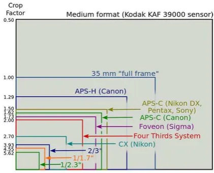
The UNGSC has specific requirements on the image resolution and operational time. As mapping results, they require a seamless orthorectified mosaicked natural colour (RGB) vertical aerial image of 0.1 m or finer spatial resolution for a minimum 2.5 km2 coverage by a single flight mission within 24 hours control/processing station, communication devices such as radios, modems, an antenna. The aerial vehicle should fly for 60 min. at minimum with mounted payload and be VTOL (Vertical Take Off and Landing) type with an automated flight capability. The wind resistance might be up to 14 m/s, it’s in case they need to operate the system in the wind. They consider an optical camera and GPS essentially as mission sensors and it is better if there are image sensors of multiple wavelength beyond visible range such as NIR, IR, thermal sensors or video cameras. The optical camera is expected to be full frame sensor (24x36 mm) or lager sensor size to produce larger images. The classification of cameras according to the sensor size is shown in Figure 1.
Figure 1. Image sensor size comparison
Position accuracy achieved by a GPS receiver should be less than 2 pixels in terms of terrain displacement. The ground control/processing station has to include a fully automated flight planning and mainstream remote sensing and photogrammetry post processing software without manual intervention so that
they can acquire updated geospatial products without operation and photogrammetric experts in an operation field. The communication between the aerial vehicle and ground station can be established by wireless devices such as telemetry, Wi-Fi and then data processing can be performed simultaneously with data acquisition. We have various commercial or open-source UAV image processing software, for example Photoscan, Pix4D, DroneMapper, UASMaster Inpho, etc. They want choose the most reliable one among the software to produce a single seamless orthorectified mosaicked image of less 0.5 pixel RMSE (Root Mean Square Error) on a desired area.
3. UAV BASED AUTOMATIC MAPPING SYSTEM
We design an operation concept of the UAV mapping system for supporting UN field operations, as shown Figure 2. Once the UN field operations are needed, we define the extent of the target area and required resolution of the geospatial information. In the preparation stage, flight planning is conducted for acquisition of sensory data to fulfil the specified coverage and resolution. In the following data acquisition stage, sensory data are acquired in the air while the UAV multi-sensor system flies along the flight path. After the data acquisition, the sensory data is transmitted to a ground station in real-time or on-line. By rapid georeferencing and geo-data generation, we then obtain the geospatial information of the area such as DEM/DSM, orthoimages, etc. Finally, the geospatial information can be used to determine the appropriate responses and the responses will be distributed to the field operation teams with an appropriate updated geospatial information, who have to monitor disputed regions or perform rescuing and restoring operations.
Figure 2. Operation concept of the UAV mapping system
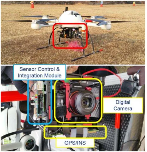
This system can provide the updated geospatial information of a target area in a rapid and automatic way using a UAV based multi-sensor system. In detail, we can divide the system into hardware and software systems. The hardware system acquires sensory data through autonomous flight over a specified area and transmits them to the ground station. It consists of a micro UAV platform, a digital camera, a GPS, a MEMS IMU, and a control board that records the sensory data tagged with their acquisition times and transmits them to the ground station. We employ md4-1000 which weighs 2,650 g and fly during about 45 min. Its maximum allowance weight is 1,200 g and operation height is 1,000 m. The model and main specifications of the sensors mounted on the UAV are summarized in Table 1. All the sensors are integrated with the sensor support modules and mounted on a rigid frame as shown in Figure 3.
Sensor Model Specification
Roll&Pitch accuracy (DGPS) : 0.03 deg
Heading accuracy (DGPS) : 0.28 deg
Table 1. Model and main specifications of the sensors
Figure 3. Hardware system of the UAV mapping system
The software system processes the collected data and generates geospatial information as well as generate flight plans. The software system includes four sub-modules, flight planning, data quality test, georeferencing and ortho-rectification modules. From the flight planning module, we obtain an optimal flight path to acquire images to be appropriately used for the generation of the orthoimage of a predefined target area with a specified resolution using the specification of the hardware system, such as the focal length, pixel size, detector size, etc. All the acquired data during the flight are not always suitable for data processing. Some of the acquired images may have a severe shift or rotation between images or blur due to severing turbulence. Those data are not suitable to data processing and thus we need to check the data quality and remove them out of input into the georeferencing and orthorectification modules.
After the data quality test, we perform image georeferencing in real-time at the georeferncing module. The georeferencing module is developed by combining image matching (Tanathong and Lee, 2014) and bundle adjustment (Choi and Lee, 2013) without any GCP (Ground Control Point). This indirect georeferencing method can compensate GPS/INS performance and there is no need for users’ intervention because the process doesn’t require any GCP. With the georeferenced images, DEM and orthoimages are generated rapidly at the orthorectification module. In this module, tilt and relief displacement of the images are eliminated based on differential rectification using a DEM, which is assumed as a flat terrain with the average elevation to reduce processing time.
4. TEST OPERATION AND RESULTS
We are still developing the UAV mapping system for supporting UN field operations. While most of the hardware system is constructed, the development of the software system is not completed. Hence we apply the UAV mapping system partially to field tests and introduce the results in this chapter.
4.1 Test Operations
The test field is a small village of Icheon in Korea, including residential zones, agricultural lands and forests as shown in Figure 4. We acquire UAV images at three different altitudes, 88 m, 200 m and 300 m. In case of 88m, we use the camera with the lens of focal length of 35 mm and in the other cases, we use the lens of focal length of 24 mm for a larger coverage. The area covered by each flight mission are 0.12 m2, 0.37 m2 and 0.64 m2, respectively. Details of each dataset are summarized in Table 2. In all of the missions, we can acquire images with the resolution higher than 10 cm, which the UNGSC requires.
Figure 4. Test field and flight path with flight altitude of 200 m
Dataset 1
Table 2. Model and main specifications of the sensors
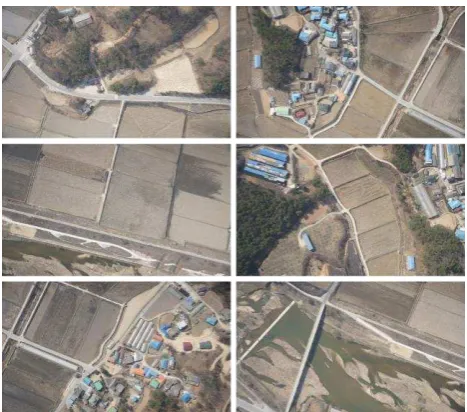
Most of micro UAVs have limitation in terms of flight duration and the area covered by a mission is small. To overcome this limitation, we can reduce the number of strips and make the flight altitude as high as possible. As shown in Figure 5, we can recognize the high resolution and clarity of the images even though images are acquired at the altitude of 300 m.
Figure 5. Sample images acquired at the flight altitude of 300 m
During the field test, we have a restriction on the flying altitude. When we don’t have the restriction, we can fly the UAV system at about 586 m by satisfying the UN’s requirement on the image resolution of 0.1 m. We check the feasibility of our mapping system by a simulation with some parameters described in Table 3. With these parameters, we determine a flight path and image configuration as shown in Figure 6. The number of strips and images per a strip are 4 and 23, respectively. The total number of images is 92 and the coverage of a single image is 400 m by 600 m. When we acquire images with the same condition, the whole flight time is about 22.4 min which is less than 45 min, the maximum flight time of our proposed UAV system and includes climbing (3.3 min.), acquisition (9.8 min.), turning (1.6 min.) and others (8 min.) time. Based on the simulation results, the target area can be covered with 22.4 min. flight time, which can be possible with a single flight mission. With the acquired 92 images, whose overlap ratio is 80 % and sidelap ratio is 60 %, the orthorectified image mosaic of the target area can be generated within 24 hours.
Parameters Values Notes
Target area 2.5 km2 2 km x 1.25 km
Flight altitude 586.2647 m
Focal length = 35 mm Pixel size = 5.97 um Ground resolution = 10 cm
Overlap 80 % Along track
Sidelap 60 % Cross track
Flight speed 3 m/s Rate of climb 12 m/s Cruising speed
Table 3. Main simulation parameters
Figure 6. Flight path and image configuration
We also survey GCP (Ground Control Points) using the RTK-GPS with 1.5cm precision. The GCP are used to verify the accuracy of image processing results as CP (Check Points). The total number of the GCP is 96 and we can examine the distribution of the GCP in Figure 7.
Figure 7. The distribution of GCP in the test field
4.2 Processing Results
All the acquired images are synchronized with the GPS time. Therefore, the position/attitude of the platform provided by the GPS/IMU are interpolated at the image acquisition rate and used for the determination of the initial EOP (Exterior Orientation Parameters) of the images. To determine the initial EOP using the GPS/IMU data, we have to know the mounting parameters which describe the geometric relationship between GPS/IMU unit and a camera. Therefore, we perform system calibration for the determination of the mounting parameters before data processing for the generation of spatial information. Depending on the mathematical model, we have two main approaches for system calibration, two-step procedure and single-step procedure (Habib, 2010). We select the two-step
procedure, the mounting parameters are estimated by comparing the position and orientation results derived from GPS/IMU data with the EOP determined by a bundle adjustment solution using GCP. When we define system calibration parameters and coordinate systems illustrated in Figure 8, we estimate mounting parameters through the system calibration procedure as shown in Table 4. Finally, we determine the initial EOP of each image by combining the mounting parameters and GPS/IMU data.
Figure 8. Coordinate systems and involved parameters in the system calibration
Mounting parameters Values Precision
(m)
x -1.529 0.077
y 0.133 0.155
x 0.543 0.126
(deg)
� 179.889 0.126
� 0.168 0.060
� 89.596 0.070
Table 4. Estimated system mounting parameters and their precision
By applying the acquired images and their initial EOP to our software system, we can perform image georeferencing and orthorectification. As the results, we finally produce individual orthoimages and mosaics of the test field area. To verify the accuracy, we compare estimated coordinates using our system with measured coordinates from field survey on CP. As the comparative results, the RMSE of estimated coordinates on CP are shown in Table 5. Our system can achieve the accuracy of 1~5 m without any GCP while the accuracy is within ± 20 using GCP. Hence our system are considered to acquire meaningful geospatial information rapidly in interested area.
Dataset 1 (H: 88m)
Dataset 2 (H: 200m)
Dataset 3 (H: 300m) No
GCP Uing GCP
No GCP
Uing GCP
No GCP
Uing GCP XY(m) 0.289 0.249 1.914 0.257 4.888 0.065 Z(m) 1.837 0.340 2.999 0.141 3.125 0.087
Table 5. RMSE of estimated coordinates on CP
We can compare orthoimages produced by our software and those serviced by Googel Earth, as shown in Figure 9 as well. The quality of the orthoimages must be quite satisfactory enough to be applied to the GIS supporting UN field operations. By our software, we can generate orthoimages with higher resolution than those of Google Earth at much faster speed. We take less than 30 min. to generate the individual orthoimages
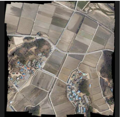
totally. From the individual orthoimages, a mosaic is generated as shown in Figure 10. These orthoimages are useful for users to recognize the changes in a mission area immediately.
Figure 9. Orthoimages produced by our software (left) and served by Google Earth (right)
Figure 10. Orthoimage mosaic (flight altitude: 200 m)
5. CONCLUSIONS
In this study, we propose an automatic UAV mapping system for supporting UN field operations. Through the field operations, we can successfully acquire sensory data such as images and GPS/IMU data of the test field. By processing the data, we can obtain the high quality geospatial information like orthoimages. The geospatial information produced by our system will be useful for many important tasks in UN field operations, such as monitoring disputed areas, performing SAR (Search and Rescue) and restoring disaster areas and so on. Field operation teams can recognize the changes in a mission
area immediately through the geospatial information. In near future, we will complete the data processing pipeline and continue more diverse tests to evaluate our system on the accuracy and processing time.
ACKNOWLEDGEMENTS
This research was supported by a grant (14NSIP-B080144-01) National Spatial Information Policy Research Program funded by Ministry of Land, Infrastructure and Transport of Korean government.
REFERENCES
UN. 2010. Department of Peacekeeping Operations. http://www.un.org/en/peacekeeping/about/dpko/ (accessed April 13, 2016).
UNGSC. 2010. Service for Geospatial, Information and
Telecommunications Technologies.
http://www.unlb.org/Services/SGITT (accessed April 13, 2016).
ESRI. 2011. What if GIS. http://www.esri.com/what-is-gis (accessed April 11, 2016).
Choi, K, Lee, J. and Lee, I., 2011. Development of a Close-range Real-time Aerial Monitoring System based on a Low Altitude Unmanned Air Vehicle. Journal of KOREA Spatial Information Society, 19(4), pp. 21-31.
Tanathong, S. and Lee, I., 2014. Using GPS/INS data to enhance image matching for real-time aerial triangulation. Computers & Geosciences, 72, pp. 244-254.
Choi, K. and Lee, I., 2013. A Sequential Aerial Triangulation Algorithm for Real-time Georeferencing of Image Sequences Acquired by an Airborne Multi-Sensor System. Remote Sens., 5(1), pp. 57-82.
Habib, A., Kersting, A. and Bang, K. I. 2010. Comparative Analysis of Different Approaches for the Incorporation of Position and Orientation Information in Integrated Sensor Orientation Procedures. In: Proceedings of Canadian Geomatics Conference 2010 and ISPRS COM I Symposium, Calgary, Canada.