LOCALIZED SEGMENT BASED PROCESSING FOR AUTOMATIC BUILDING
EXTRACTION FROM LiDAR DATA
Gaurav Parida a, K. S. Rajan a
a
Lab for Spatial Informatics, International Institute of Information Technology Hyderabad, India - 500 032 (gaurav.parida@research., rajan@)iiit.ac.in
Commission II, WG II/4
KEY WORDS: Building Extraction, Footprint Extraction, LiDAR, Object Detection, Point Cloud
ABSTRACT:
The current methods of object segmentation and extraction and classification of aerial LiDAR data is manual and tedious task. This work proposes a technique for object segmentation out of LiDAR data. A bottom-up geometric rule based approach was used initially to devise a way to segment buildings out of the LiDAR datasets. For curved wall surfaces, comparison of localized surface normals was done to segment buildings. The algorithm has been applied to both synthetic datasets as well as real world dataset of Vaihingen, Germany. Preliminary results show successful segmentation of the buildings objects from a given scene in case of synthetic datasets and promissory results in case of real world data.
The advantages of the proposed work is non-dependence on any other form of data required except LiDAR. It is an unsupervised method of building segmentation, thus requires no model training as seen in supervised techniques. It focuses on extracting the walls of the buildings to construct the footprint, rather than focussing on roof. The focus on extracting the wall to reconstruct the buildings from a LiDAR scene is crux of the method proposed. The current segmentation approach can be used to get 2D footprints of the buildings, with further scope to generate 3D models. Thus, the proposed method can be used as a tool to get footprints of buildings in urban landscapes, helping in urban planning and the smart cities endeavour.
1. INTRODUCTION
1.1 Literature Survey
Building segmentation tasks in the industry is still more focussed on manual and semi-automatic techniques. The automatic techniques have been explored, but they have some shortcomings. They involve the use of composite data along with LiDAR data. Getting multiple sets of data for the same area decreases the chance of data generation. Existing public dataset aren’t very high density data and lack the spatial resolution to retrieve or reconstruct the building model from the LiDAR data.
Existing work done in building segmentation from LiDAR involve multiple approaches based on the point density, additional supplementary data like co-located images, identification of roof and its extension to building footprints. In algorithms based on the generation of the roof plane (Tarsha-Kurdi, 2007; Elaksher, 2002), the identification of the best roof plane, though not the best fitting one, needs a rather high point cloud density controlled by the choice or voting in the parameter space of the transform function.
Tarsha-Kurdi (2007) used a RANSAC based 3D Hough transform to segment buildings. Advantages of RANSAC gives us faster and cleaner results. The shortcoming of it is that it finds the best roof plane rather than the best fitting plane and it's dependency on high density point cloud data. (Elaksher, 2002) also segmented buildings using a transform similar to Hough transform, where voting is done in an plane parameter space and the finding a space with larger number of points. It removes ground points using a minimum ground filter. It identifies the
holes in them. After the roof planes are constructed wireframes are made to construct "roof border points".
Zhang (2006) proposed contour based analysis of LiDAR data to segment buildings. Due to the difficulty of finding the optimal voting size in the Hough transform and the challenges in regularising the raw footprint obtained. It proposed a morphological operation for ground points removal. Subsequently, region growing plane fitting algorithm was used to get the building footprints and it was de-noised by Douglas-Peucker algorithm. LiDAR point density is crucial for the optimal results. (Yan, 2015) used global minima of the energy functions derived from the 2D building topology to segment buildings. It proposed using the snake algorithm (dynamic programming based graph topology extraction algorithm) which finds the global optima in polynomial time. The raw topology constructed is simplified using the Douglas-Peucker algorithm. The 3D models are generated and subsequent refining of the footprints from the 3D models is done.
remove the tree edges etc. (Siddiqui, 2014) co-planarity of the non-ground LIDAR points is measured using the Delaunay triangle neighbourhood algorithm. The lines obtained from above use their mid points of the segments as seed points for region growing method to segment buildings. Further, refinement to remove tree planes using point ratio, object shape information, height gap. Using height based thresholding different planes are separated.
Current methods are more top-down nature with major focus on footprint creation from the roof without using other available features present in the LiDAR data. The works focussing on roof based building reconstruction rely on the top-view of the building only, which may not match or be identical, ex: when the roof of the given building extends beyond the edge of the building. Thus, current methods relying on the roof planes will extract a footprint that is larger than the accurate value. The good performance of current methods run successfully on low-rise buildings and perform poorly in high-low-rise buildings. The high-rise buildings can be handled in a better fashion in our proposed algorithm.
1.2 Objective
Most of the current methods are extensively dependent on additional information requirement or the empirical domain knowledge about the LiDAR data beforehand. This leads to scaling up issues with the current approaches. Thus, to overcome such challenges we propose the need for a better and more geometry based parameterized approach to segment buildings from a given LiDAR scene.
Our work takes these different ideas of height thresholding, planarity of roof surfaces etc to formulate a composite new technique to segment buildings from a LiDAR scene. Further detailed analysis of the method proposed is explained in Section 3 of the paper. The focus of the paper is to segment both rectilinear as well as non-rectilinear shaped objects from the given scene.
2. DATA MODEL AND SIMULATION
2.1 Synthetic Dataset - SimLiDAR
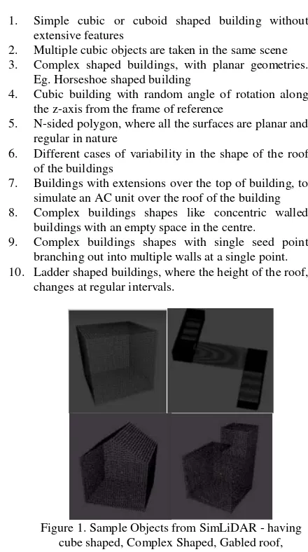
Sim lidar is a synthetic data set created to test the segmentation algorithm. The objects present in sim-lidar vary from simple objects like cube shaped buildings. Incrementally, the complexity of the buildings increases like gabled shaped buildings, ladder shaped buildings, complex shaped buildings with shape of ‘L’, ‘U’, ‘T’ etc.
The objects are stored in the X, Y, Z format, where every line of the file signifies a point in the point cloud. The LiDAR files
the z-axis from the frame of reference
5. N-sided polygon, where all the surfaces are planar and regular in nature
6. Different cases of variability in the shape of the roof of the buildings
7. Buildings with extensions over the top of building, to simulate an AC unit over the roof of the building 8. Complex buildings shapes like concentric walled
buildings with an empty space in the centre.
9. Complex buildings shapes with single seed point branching out into multiple walls at a single point. 10. Ladder shaped buildings, where the height of the roof,
changes at regular intervals.
Figure 1. Sample Objects from SimLiDAR - having cube shaped, Complex Shaped, Gabled roof,
Buildings with extensions
2.2 Using Blender to simulate complex LiDAR objects
Programming curvilinear objects is a different challenge of its own. Hence, objects are created using Blender to simulate further complex objects using Blender. The output file being generated by the program is saved in the format of obj.
The density of the object can be increased and decreased by using the subdivide tool of the program. The subdivide tool is used to increase fragmentation of the object into multiple number of the points. Thus, leading to the increase in the spatial resolution of the scene. Finally, the designed 3D model needs to be exported in the format of obj for further parsing.
Figure 2. Sample Objects created from Blender (a) Building with minarets (b) Building with centre courtyard
2.3 Vaihingen Dataset
Vaihingen dataset is the ISPRS benchmark dataset on Urban Classification and 3D Building Reconstruction. The primary objective of such dataset is for object classification and building reconstruction tasks.
[http://www2.isprs.org/commissions/comm3/wg4/tests.html]
Figure 3. Vaihingen Dataset
The ALS data of three specific regions is provided for testing purposes of building extraction algorithms. The three areas provided have unique characteristics of their own, explained below:
Area 1: "Inner City" contains historic buildings having complex shapes and some trees
Area 2: "High Riser" contains residential buildings that are surrounded by trees
Area 3: "Residential Area" represents purely residential area with small detached houses.
3. ALGORITHM
The processing pipeline was initially tested with the synthetic data, which is a high density data. The major steps of the algorithm consists of taking the non-ground points from a LiDAR scene and extracting walls from the given buildings. After different walls have been constructed, the next task is to combine all such segments into a close shaped polygon to form the footprint of the building.
The non-ground points in a given scene is generated from the lasground application, part of the LAStools package [https://rapidlasso.com/lastools/]. The non-ground points of lasground is filtered and stored as TXT format. This text file is used as the input for the whole processing pipeline.
Figure 4. Flowchart of the building segmentation algorithm
The ISPRS Benchmark dataset which simulates the real world LiDAR data has much lower point density, where we can't differentiate between an interior roof point and a wall surface of the building. Thus, to adapt to such low density data, we propose an additional rule based framework to remove the over segmented regions in a segmentation task. Here, there are very less number of points with multiple return points on the outer surface of the building. Hence, to tackle this lack of density, the algorithm was modified as explained in the subsequent sections of 3.6.
3.1 Seed Point Extraction
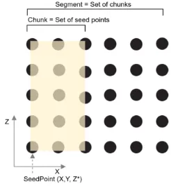
A given building is made up of different wall segments. The wall segments are made up of different chunks. A chunk is made up of different seed points. Seed point is a (X, Y, Z*) point in the point cloud which might be part of the building. The value of the Z varies, while the X and Y coordinates remain same for a given seed point.
Figure 5. Visual representation of a seed point, chunk and segment.
3.2 Chunk Segmentation
chunk and the rotation increment to find a chunk. Higher the number of points required to be in a chunk, it will segment large objects only from the scene and vice versa. Similarly, a very small rotation increment will give highly dense chunks in a given scene. The runtime of the program is inversely proportional to the rotation increment parameter and directly proportional to the number of seed points required in a chunk. Thus, chunks are the building blocks of the walls or segments in our technique. If no chunks are identified, no walls can be formed.
3.3 Wall Extraction
3.3.1 Merging Chunks: As we had seen earlier, that multiple seed points combine to form a chunk. Similarly, multiple extracted chunks are merged together to form a wall section. The merging of the chunks gives the respective walls of the buildings separately. The criteria of the merging of consecutive chunks rely on the angle between the respective normals of the plane obtained from the chunk. If the angle between the normals of the plane is within a threshold level, they are merged to be part of the same wall. The threshold angle between the normals is a user-defined metric.
The motivation to include the angle as a parameter between two chunks is to segment curved surfaces from the scene. The curved objects don't have distinct edges or boundaries which can be segmented separately. Thus to incorporate curved walls and surfaces, the normals between the chunks are used to segment them as a single entity.
The angle between the normals of the two segments is crucial to segment curved surfaces from the LiDAR scene. Having a very large threshold angle might lead to under-segmentation where the close by objects might get identified as part of the same object. Having a very small threshold angle might not identify the curved wall as a single unit, rather as multiple units (case of over segmentation).
Figure 6. Localized sliding window movement of chunks for segment identification
wall without any over segmentation or under segmentation. The common points between the consecutive chunks ensures that the normals of the planes of the chunk don’t vary drastically at short increments. Hence, helping further to segment curved walls in a gradual manner.
Figure 6 shows two consecutive chunks under consideration. Here we can see that the normals of the respective chunks are constructed. If the normals intersect within the threshold angle or are parallel to each other, then both the chunks are added to be part of the same wall. Note that all the outer surface points have multiple return points which are well spaced and hence they are part of the seed points and the other remaining points don't form the part of the seed points.
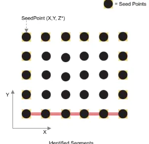
3.3.3 Z-profile Matching: This sub-step of the processing pipeline ensures that the consecutive seed points in a given segment are similar to each other and don’t vary drastically. The reason of Z-profile matching ensures that the height and the pattern in a segment remains constant over the whole segment. The measure of similarity used in our work relies on finding the edit distance between the consecutive seed points. If the edit distance between the points is above a threshold, then the segments won’t be considered part of the same wall and will be split as different walls. The exact use case of this feature can be seen the building with ladder shaped extension, as discussed in Section 4.
Figure 7. Extracted segment shown in Red (Top view)
3.4 Cyclical Extension of Wall Segments
(a) (b)
Figure 8. (a) Identification of wall segments in a given scene (b) Cyclical Merging of segments to form potential building
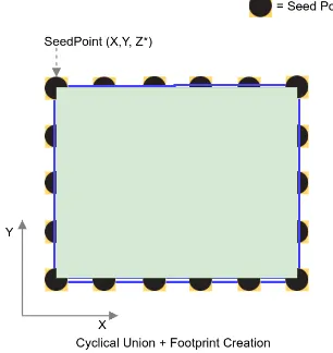
3.5 Footprint Creation and Merging
Footprint creation and merging step involves the merging of completely overlapping identified buildings candidates. In the footprint creation step, we merge the different identified segments. The merging of different segments works on the principle of cyclical nature of the segments of the building. All the segments of any buildings have a common intersection point aka edge point. All the segments merge in this fashion, and end when the new segment repeats it occurrence.
After the respective potential building footprints have been identified, the next step of the processing pipeline is to do some post-processing, which involves merging of overlapping potential buildings. The requirement of such post processing is justified in the case of some specific buildings like buildings with varying roof surface like a ladder shaped building or a building with minarets, building with holes like a centre courtyard. These cases have been extensively discussed in the observation section of the paper.
Figure 9. Footprint creation of the building
3.6 Density Based Clustering - Adaptation to real world data
In case of real world data, the point cloud can be of low density, with lack of points to segment the walls from the object in the scene. To adapt to this challenge, we made some changes to the algorithm mentioned previously. The modification in the respective sub-parts of the processing pipeline is mentioned below.
3.6.1 Segment Identification: The segment identification step with respect to the density based clustering has a very small rotation increment and high points threshold. This is done to retrieve a very dense network of segments in the given scene about the different buildings.
3.6.2 Neighbouring Cluster Separation: After the potential segments have been extracted from the scene, same as seen in Section 3.2. The next subtask of the processing pipeline is to separate multiple clusters of segments from each other. The similar segments are clustered together to form an approximate extent of the “potential” building.
A proximity based measure is used to segment the different blobs of segments from each other. If two segments of different classes are nearby a segment from some other class, then both subsequent steps to eliminate such non-building clusters.
Since, the segments contain only those points where the height of the points in the set are similar to each other. Thus, overlapping objects in the scene are segmented separately on the basis of previous assumption.
3.6.3 Density Evaluation: The point cloud of a building being uniform, is distributed evenly compared to that of trees. This uniformity and high density of segments distribution gives us a clear metric to evaluate the density of the cluster of segments obtained from the previous step, in order to separate the non-building clusters. Such clusters are thus filtered away from the final results.
The density evaluation step proposed in the work is input data dependent and hence makes the algorithm semi-automatic with respect to low density LiDAR data. The filtering parameter proposed in the work shouldn’t be considered to be specific. Rather, multiple such similar filters can be created to remove the non-building clusters.
Some examples of the other filters that can be incorporated into the algorithm for separating the non-building clusters can be on the basis of:
1. Sum of the degree of connection with other nodes in the same cluster
2. Height thresholding techniques to remove near ground vegetation and other non-ground points.
3. Average Height Variation in the cluster by putting the respective height values into the designated bins. 4. Deriving features from the Elevation distribution of
points in the given cluster
where n = number of seed points in the cluster
N = number of all potential segments connected with the boundary of the cluster
3.6.4 Footprint Extraction Using Local Convex Hull: After the clusters have been further filtered using the density of the cluster, we are left with the task of creating footprints of the building. Rather than cyclical completion of the segments as seen in the sample data processing, we formulate the creation of local convex hulls to create the building footprints.
The proposal to use local convex hull is primarily hinged on that fact that, the buildings with overhangs or extension will result in incorrect footprints. If we take the conventional convex hull formulation, all the outer surface points won’t be covered in the previous instance.
In a local convex hull, we chose a point in the convex hull and take n neighbouring points and create a new convex hull among those points. After such multiple localized convex hulls are created, we merge them to get the final convex hull, which signifies the footprint of the building. Thus, the flowchart of the modified approach of density based clusters is shown below
Figure 10. Footprint creation of the building
4. OBSERVATIONS AND CONCLUSION
As stated earlier the segmentation algorithm focussed on extracting the facades of the buildings to construct the footprints of the buildings. The potential advantages of our algorithm is based on the non-dependence on any other form of supplementary data. The algorithm was tested on objects of both simulated and real world data.
The simulated objects consisted of more variety of objects compared to the real world data, which had specific kinds of buildings i.e. flat roofed and gabled roofed buildings. Thus, the
The algorithm was tested incrementally starting from simple objects like cubes and cuboids, then moving onto multiple objects in a single LiDAR scene. Then the complexity progressed to peculiar buildings like ladder shaped buildings or buildings with minarets.
In case of buildings with minarets, the sections consisting of minarets, owing to the variation in the Z-profile are segmented separately compared to the other parts of the building. Thus, for the same building we get 5 different footprints. 4 small footprints, signifying the 4 minarets present in the buildings, which are segmented out separately and the remaining footprint covering the rest of the building. Since the footprints of the respective minarets occur completely within the footprint of the remaining part of the buildings. All the 5 footprints are merged to a single footprint to signify the building with minarets.
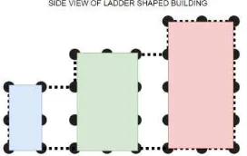
The similar case happens with a ladder shaped building where the Z profile sub-sections consisting of stepped ladder are separated into different sections in spite of being part of the same wall. The side profile of such ladder shaped building is shown below:
Figure 11. Side-View of the Ladder shaped building where the same wall is divided into three sub-parts owing to the different
XZ-profile.
4.2 Observations on the real world dataset
Figure 12. Real world LiDAR, where we can see that the walls don't have multiple return values and not easily separable (a)
As stated earlier, the real world benchmark dataset provided by ISPRS of Vaihingen, Germany is a very sparse data set, where the wall surface can't be easily separated from a interior point of the building. Hence, we overestimate the interior part of the building to be part of the wall surface as well and formulate a strategy to segment only the building segments.
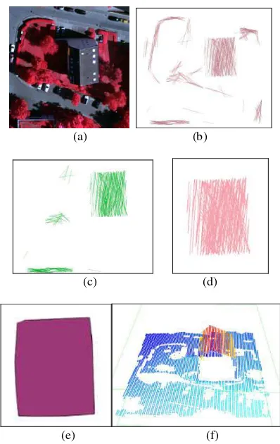
A neighbourhood based clusters are formed based on the proximity and height similarity metric of the close by segments belonging to different clusters. After the respective clusters have been formed, the rule based framework is constructed to segment those regions only that form a building (in the current data, they very dense compared to other clusters). Below shows a sample taken from a small part of Area 2 of the VA dataset.
Figure 13. (a) Satellite Area of study (b) Segment Extraction (c) Remaining Segments after rule based Height thresholding (d) Remaining Segments after Rule based filtering (e) Final
local convex hull of the potential building (f) Gabled roof building segmented from the input LiDAR data shown in red
5. FUTURE WORK
In our work, we tried to tackle the problem of segmenting buildings only using the LiDAR data of the area and no other supplementary datasets. The proposed technique is a
training and modelling of classifiers. The problem was formulated in a bottom up manner, where we first created synthetic datasets for testing our approach and then jumped over to the real world datasets for verification of the hypothesis.
The objective of building detection and footprint identification was successfully achieved. Building shaped objects were segmented both from the simulated dataset and the real world density LiDAR data for further enhancements to the algorithm. Further analysis of the approach against completeness and/or correctness of the segmentation needs to be carried out for a few real world datasets. Better rule based filters could be constructed in a tool format, which could readily be used to filter and visualize LiDAR cloud points. The final extension of the work can explore on the ways to fuse terrestrial and aerial LiDAR datasets to produce better quality results of object segmentation and classification in a real world scenario.
ACKNOWLEDGEMENTS
The Vaihingen data set was provided by the German Society for Photogrammetry, Remote Sensing and Geoinformation (DGPF) [Cramer, 2010]:
http://www.ifp.uni-stuttgart.de/dgpf/DKEP-Allg.html
REFERENCES
Tarsha-Kurdi, F., Landes, T. and Grussenmeyer, P., 2007, September. Hough-transform and extended ransac algorithms for automatic detection of 3d building roof planes from lidar data. In Proceedings of the ISPRS Workshop on Laser Scanning (Vol. 36, pp. 407-412).
Elaksher, A.F. and Bethel, J.S., 2002. Reconstructing 3d buildings from lidar data. International Archives Of Photogrammetry Remote Sensing and Spatial Information Sciences, 34(3/A), pp.102-107.
Zhang, K., Yan, J. and Chen, S.C., 2006. Automatic construction of building footprints from airborne LIDAR data. IEEE Transactions on Geoscience and Remote Sensing, 44(9), pp.2523-2533.
Yan, J., Zhang, K., Zhang, C., Chen, S.C. and Narasimhan, G., 2015. Automatic construction of 3-D building model from airborne LIDAR data through 2-D snake algorithm. IEEE Transactions on Geoscience and Remote Sensing, 53(1), pp.3-14.
Awrangjeb, M., Ravanbakhsh, M. and Fraser, C.S., 2010. Automatic detection of residential buildings using LIDAR data and multispectral imagery. ISPRS Journal of Photogrammetry and Remote Sensing, 65(5), pp.457-467.
Applications (DlCTA), 2014 International Conference on (pp. 1-8). IEEE.
Siddiqui, F.U., Teng, S.W., Lu, G. and Awrangjeb, M., 2014, November. Automatic Extraction of Buildings in an Urban Region. In Proceedings of the 29th International Conference on Image and Vision Computing New Zealand (pp. 178-183). ACM.
Wang, Z. and Schenk, T., 2000. Building extraction and reconstruction from lidar data. International Archives of Photogrammetry and Remote Sensing, 33(B3/2; PART 3), pp.958-964.
Arefi, H. and Hahn, M., 2005, July. A hierarchical procedure for segmentation and classification of airborne LIDAR images. In International Geoscience and Remote Sensing Symposium
(Vol. 7, p. 4950).
Wang, J. and Shan, J., 2009, March. Segmentation of LiDAR point clouds for building extraction. In American Society for Photogramm. Remote Sens. Annual Conference, Baltimore, MD (pp. 9-13).
Chen, L., Teo, T., Rau, J.Y., Liu, J. and Hsu, W., 2005, July. Building reconstruction from LIDAR data and aerial imagery. In IGARSS (pp. 2846-2849)