i
tif c n
e C
i o
c n
S f
l e
a r
n e
o n
i c
t e
a
2
n
r 0
et 1
1
n I
ISC 2011
Proceeding of the International Conference on Advanced Science,
Engineering and Information Technology 2011
Hotel Equatorial Bangi-Putrajaya, Malaysia, 14 - 15 January 2011
ISBN 978-983-42366-4-9
ISC 2011
International Conference on Advanced Science, Engineering and Information Technology
ICASEIT 2011
Cutting Edge Sciences for Future Sustainability Hotel Equatorial Bangi-Putrajaya, Malaysia, 14 - 15 January 2011
SR
IE
AV IUNIT
NI
ESE
D K
O B
IN N
R AG
J
A A
LA SA
E N
P M
N A
A L
U A
T Y
A S
S A I
R
EP
N I
NO OD ITAICOSSA STNEDUTSNAISEN
Organized by Indonesian Students Association Universiti Kebangsaan Malaysia
Proceeding of the
Comparison of Electric Karting Modelling Using
Matlab
®
/Simulink
®
Software
Didi Istardi
Electrical Engineering, Batam Polytechnics Parkway st. Batam Centre, Batam, 29461, Indonesia Tel.:+62-778-469856, E-mail: [email protected]
Abstract
—
Electric karting was modelled for efficiency and energy consumption study. The model includes models of battery, power electronics converter, electric motor, and vehicle dynamic of a typical 48 seconds track driving schedule in Europe competition. The regenerative braking energy was also considered in simulation. The comparison of different type of electric motors – direct current (DC) motor, induction motor, permanent magnet synchronous motor (PMSM), brushless direct current motor (BLDC), and switched reluctance motor (SRM) - and batteries – Lead Acid, Lithium Metal Polymer (LMP), Nickel Metal Hybride (NiMH) - also were investigated. Finally, the efficiency was compared between the different type of electric motor and battery. The result shown that the SRM and LMP Battery has a high efficiency and performance compare to the others.Keywords— Electric Karting, efficiency, energy consumption, loss modelling.
I. INTRODUCTION
Recently, there are many researches that interest in an electric and hybrid vehicle area [1-4]. Environmental consideration –global crisis- and energy cost are the main reason of the research in this area. Electric vehicle has many advantages compare to internal combustion engine (ICE) vehicle such as more efficient, pollution free, low operating cost, and can operate in any range of speeds.
One of the developments in the electric vehicle is research on electric kart racing or karting. The different between the normal electric go-kart and electric karting is their energy consumption and acceleration characteristics. In electric karting, the energy and acceleration that was used higher than in the electric go-kart. According to this condition, the electric karting that would be used as an input for simulation is the small ICE karting for children (8-12 years old) because it is easier to introduce a new concept to children compare to adult. Therefore, the research is focus on comparison between some components that will be used to convert the small ICE karting to small electric karting.
The proposed electric karting could fulfill the following requirement: give zero pollution, shall be optimized for 10 minutes heat in full race and 3 minutes for in and out laps. This drive also shall be able to start without any assistance while the driver seated.
The paper is organized as follows: In the next section, a basic theory of electric karting components is presented. In Section III, a description of the ICE karting drive cycle is given. The selection of electric karting component will be presented in Section IV. Section V and VI presents results of simulation using MATLAB®/Simulink® software and discussion of the results. Finally, the conclusions are made in section VII.
II. ELECTRICKARTINGDRIVESYSTEM
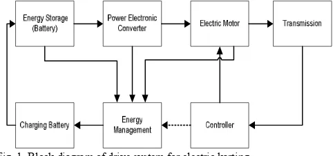
A simple electric karting consists of a drive system (transmission, electric motor, and power electronics) and energy storage (battery) [5] as seen in Figure 1.
Fig. 1 Block diagram of drive system for electric karting.
motor. The voltage and current output of the battery are maintained to match the ratings of the electric motor. The electric motor converts electrical energy supplied by the battery into mechanical energy. A transmission transforms the mechanical energy into a linear motion. Speed and torque are adjusted using the gear box. The gear can transmit the rotational force at different speeds, torque, and directions. A controller and energy management control the speed and direction of the electric karting, and optimize the energy conversion from the battery to the transmission. The battery can be charged from the line power and also from regenerative braking energy.
A. Storage Energy (Battery)
The complete modelling of battery is very complex procedure and required the thorough knowledge of electrochemistry. Otherwise, the modelling of battery also can use the electric circuit-based models that represent the electrical characteristic of the battery. One of the electric circuit-based models is a generic battery model. The model is a modification of the Sheppard discharge battery model that was introduced by [6]. The battery is modelled using a controlled voltage source in series with constant resistance that represent four type of battery chemistry and the output voltage can be calculated using
where E : output battery voltages[V] Eo: a open circuit voltages [V]
Q : Battery capacity [Ah] K: The coefficient of polarization i : Apparent current density [A] t : The time elapsed [h]
A : voltage drop during the exponential zone (V) B : charge at the end of the exponential zone (Ah) The simulation used some batteries as energy storage with the capacity was around 35 - 60 Ah.
Some general terms and terminologies used in battery modelling are C-rates, state of charge (SOC), open circuit voltage, cut-off voltage (end of nominal zone), nominal voltage, and battery capacity
SOC is an expression of the present battery capacity as a percentage of maximum capacity. SOC is generally calculated using current integration to determine the change in the battery capacity over time. An open circuit voltage is the voltage at the battery terminals with no load applied. The open-circuit voltage depends on the SOC of battery.
B. Power Electronics Converter
The power electronics converter will be used in this simulation is H-Bridge converter for DC Motor control and the standard six-switch three-phase bridge inverter converter for PMSM, Induction Motor, BLDC, and SRM controller. This main aim of this component is to provide a suitable mean that are used in electric motor. The power electronics component as power switching device that is used in here is MOSFET (Metal Oxide Semiconductor Field Effect transistors), IGBT (Insulated Gate Bipolar Transistor), and power diode. The controller pulse is used in this simulation is the three phase pulse-width modulation (PWM). Although
for BLDC and SRM motor controller usually uses trapezoidal wave modulation. The main losses in converter (PQ) are the conduction losses and switching losses for every
switching component and can be calculated by [7]-[8]
Q
where PQ : Power electronics converter losses [W]
Pcond,Q : the conduction losses [W]
Pswith,Q : the switching losses [W]
C. Electric Motor
The losses in the electric motor can be divided into 4 components [10]: copper losses, core losses, mechanical losses and stray losses. In this paper, only copper and iron losses will be used in simulation and analysis. Mechanical and stray losses are disregarded. The electric motor that used in this paper is DC motor, induction, PMSM, BLDC and SRM.
The main components losses of the permanent magnet DC (PMDC) motor are field circuit and armature circuit resistance. The field windings of this motor are permanent magnet that the field flux will be always constant. So, the rotor loss for this motor can be neglected and the motor losses can be expressed by
2
, R I
PlossPMDC a (3)
where Ploss,PMDC : PMDC motor losses [W]
Ra : armature circuit resistance [Ω]
I : the input current to motor [A]
The induction motor is composed of a stator circuit and a rotor circuit. In three phase induction motor, the stator circuit has three sets of coils that are separated by 1200 and
are excited by three phase supply. The rotor circuit is also design with three phase windings that are shorted internally or externally (through slip rings and brushes) [4][9]. In
where Ploss,IM : induction motor losses [W]
a two phase-on fashion, where the third phase is off. The produce of two phase voltage will be effected rotor position and the phase current in BLDC is electronically switched and also the rotor position affects the produce of two phase voltage. The signal from the rotor position sensor produces a three digit number that changes every 600 (electrical degree).
The BLDC Motor consists three main components, motor with permanent magnet in rotor side and stator winding, sensing system that sense the rotor field magnet location, and electronic commutator and control. The losses of this motor can be calculated by
2
,BLDC 2 s s
loss R I
P (6)
SRM are characterized by having salient poles at the both, stator and rotor. The rotor made of stacked steel lamination or soft iron and do not require magnet or winding [12]. In SRM, the configuration of stator consists of pole pairs located facing each other forming electrical phases such as 6/4 model, that means this SRM consists 6 stator pole (m) and 4 rotor poles. The principle of operation of SRM based on rotor position (aligned and unaligned). The unaligned position, the rotor poles is mid way between two stator poles; the flux path includes a large air gap, so the reluctance is high. Low flux density keeps the magnetic structure in its linear region and the phase inductance has a small value. Otherwise, in aligned position the flux path includes in small air gap, small reluctance.
The total losses for this motor are
2
,SRM 2 s s
loss mR I
P (7)
Where m : number of stator poles
D. Transmission Model
The drive systems must provide an enough effort at wheel to run the vehicle that can be called “traction resistance” i.e. the sum of rolling resistance, aerodynamic drag, climbing resistance and acceleration force [13]. Rolling resistance is a deformation process mechanism which occurs at the contact patch between the tires and road surface. Aerodynamic drag is the viscous resistance of air upon the vehicle. In this paper, the race track is assumed to be flat, thus the climbing resistance is neglected.
In transmission model also include a gearing mechanism between the electric motor and the load. The gear mechanism can provide the peak torque at specified speeds.
E. Regenerative Braking
Regenerative braking is a mechanism that reduces vehicles speed by converting some of its kinetic energy to other useful from of energy [14]. This energy can be use to charging the storage energy in the system such as battery. The regenerative braking is different from dynamic braking that the electrical energy dissipates as heat by passing current through large bank of variable resistor and have small effect in lower speed. Therefore, the friction brake still required as complete brake and back-up brake. The total energy of dissipation is limited by either the capacity of supply system to absorb this energy or on the state of charge (SOC) of the battery. If this condition is archived, the dynamic braking will absorb the excess energy. In regenerative braking, the electric motor acts as generator
during the braking and the transfer energy to the load which provides braking effect.
In order to capture the regenerative brake energy, the value of total drive torque always negative. For example, if the drive power from the electric motor is less than the road load but not zero then the vehicle is being decelerated due to not enough drive power to accelerate the vehicle. In this condition, the regenerative system is not working since the drive power is still positive.
III.LOADPROFILEOFELECTRICKARTINGMODEL
The load used in this paper was drive cycle of ICE karting at race day for one lap (48 seconds). This drive cycle had previously been measured by the Flap track software at Göteborg karting ring track. The speed profile of the ICE karting for a lap can be seen in Figure 2.
Fig. 2 Speed profile of ICE karting at Göteborg karting ring track
According to this speed characteristic, the traction torque at the wheel is varying between 47 Nm and -78 Nm. The negative torque indicates that the ICE karting is in deceleration or in regenerative braking region. It is clear that the regenerative braking or deceleration torque is higher than the acceleration torque. Therefore, the regenerative power used in charging the battery must be limited due to the limitation of the electric motor, power electronic converter and battery capability.
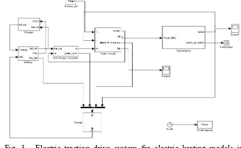
The electric karting model in Matlab/SImulink software can be seen in Figure 3.
Fig. 3, Electric traction drive system for electric karting models in Simulink
the electric karting drive system. The charger block is the block to charge the battery from the outside, but in this simulation it is assumed that there is no charging power from outside
IV.DRIVECOMPONENTS
To design electric karting, the basic requirements to get the optimum solution for the components must be achieved. According to Figure 2, the maximum power of the load profile is 6.67 kW for less than 1 second and the average power without the regenerative braking power is 3.6 kW. Therefore, the electric motor must have rating at least 5 kW.
The power electronics converter must be in the range of 75 - 160 Ampere, with variable output voltages. The converter is of 4-quadrant type, has the power of 5.5 kW and switching frequency of 10 kHz.
The energy required to run the electric karting using the battery is around 49 Wh or 1.015 Ah (the battery voltage is 48 Vdc) for 48 seconds. Therefore, to operate for 13 minutes,
the battery capacity must be larger than 16.5 Ah.
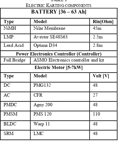
According to the specification above, the electric karting drive components can be seen in Table 1.
TABLE 1
ELECTRIC KARTING COMPONENTS
BATTERY [36 – 63 Ah]
Type Model Rin[Ohm]
NiMH Nilar Membrane 45m
LMP Avestor SE48S63 2.5m
Lead Acid Optima D34 2.8m
Power Electronics Controller (Controller)
Full Bridge ASMO Electronics controller and kit
Electric Motor [5-7kW]
Type Model Volt [V]
DC PMG132 48
AC CFR 27
PMDC Agny 200 48
PMSM PMS 120 110
BLDC Warp 11 48
SRM LMC 48
V. RESULTANDDISCUSSION
According to the data sheet of the electric motor as explained, the speed and torque at the wheel must be geared to values that have a high efficiency of the electric motor and can operate in the wide range of speeds. The result of this simulation can be seen in Figure 4.
Fig. 4 Efficiency comparison of the different electric karting
Calculating from Figure 5, the electric karting using SRM motor have highest average efficiency (77,9%) compare the others and the electric karting using induction motor is the lowest average efficiency (47,64%). In regenerative braking conditions, the efficiency of induction motor electric karting is low due to the large current in induction motor and battery. Therefore, the current and power must be limited in the electric motor and battery at regenerative braking condition. It will increase the efficiency of the system.
The energy usage in the drive system can be calculated by integration of the power usage in the drive system. The total energy used by the drive system is the subtraction of the regenerative energy from the used driving energy. The comparison of the total energy used can be seen in Figure 5.
Fig. 5 Energy used comparison of the different electric karting
Figure 5 shows that the SRM motor electric karting is the lowest of the total energy used for 48 seconds. The arrow shows the regenerative braking condition that supplies a higher energy level in short time compared to normal operation. Consequently, this energy must be considered in designing an electric traction drive system.
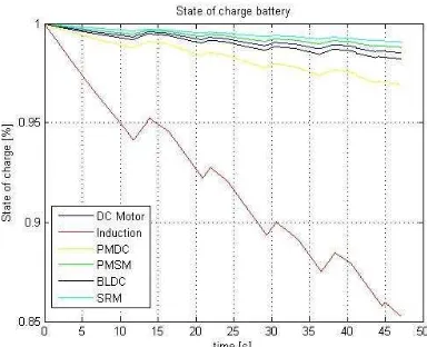
The performance of the battery in the electric karting drive system can be evaluated using the SOC of the battery during the drive cycle. The SOC of the battery can be seen in Figure 6.
Reg braking
Fig. 6 Battery performance comparison of the different electric karting
The increasing lines represent the charging of the battery from regenerative braking. It is clear that the regenerative braking energy can be used to charge the battery and reduce the energy usage in the system.
From Figure 6, at the end of simulation, the SOC of the battery was 0.9908 for SRM motor and 0.8527 for Induction Motor. If the drive cycle is assumed to be the same for other times, the storage energy can support the electric karting drive system for 13 minutes as required.
The comparison of efficiency, energy, and performance of battery is also can be seen in Table 2.
TABLE 2.
COMPARISON OF ELECTRIC KARTING
Motor Efficiency (%) Energy used (Wh) SOC
DC 77.9 86.88 0.9853
Induction 67.53 88.99 0.8527
PMDC 66.63 85.37 0.9692
PMSM 68.29 84.41 0.9881
BLDC 47.64 84.58 0.9822
SRM 64.72 81.01 0.9908
VI.CONCLUSIONS
In this paper, a MATLAB®/SIMULINK® model of an
electric karting drive system was developed. By using the efficiency model for normal and regenerative braking conditions, the models of the electric motor, power electronic converter, and battery were also obtained. In addition, the model of the ideal vehicle dynamics go-kart and charging battery and the basic step to choose the components of the electric karting drive system were
presented. The speed profile and torque profile that were used in the simulation were assessed.
The comparison of the different electric motor and battery was evaluated. The efficiency, energy used, battery performance was evaluated and compared.
Finally, the electric karting that used the SRM and LMP battery has a high efficiency and performance
ACKNOWLEDGMENT
The authors gratefully acknowledge the contributions of Prof. Torbjörn Thiringer, Anders Lindskog, and Stig Ekstrom for their help, support, and guidance during this project.
REFERENCES
[1] Istardi, Didi, Modeling and Energy Consumption Determination of
an Electric Go-Kart, Master thesis, Chalmers University of Technology, Gothenburg, Sweden, Jun. 2009.
[2] C. C. Chen, “An overview of electric vehicle technology,” Proceeding
of IEEE, vol. 81, no. 9, pp. 1202-1213, Sept 1993
[3] C. Cardoso, J. Ferriera, V. Alves, R. E. Araujo, “ The design and
implementation of an electric go-kart for education in motor control, “ IEEE International SPEEDAM 2006, pp. 1489 – 1494, May 2006.
[4] S.S. Williamson, A. Emadi, K. Rajashekara, “Comprehensive
Efficiency Modeling of Electric Traction Motor Drives for Hybrid
Electric Vehicles Propulsion Applications,” IEEE Transaction on
Vehicular Technology, vol. 56, no. 4, pp.1561-1572, July 2007.
[5] C. Cardoso, J. Ferriera, V. Alves, R. E. Araujo, “ The design and
implementation of an electric go-kart for education in motor control, “ IEEE International SPEEDAM 2006, pp. 1489 – 1494, May 2006.
[6] O. Tremblay, L-A. Dessaint. A-I. Dekkiche, “A generic battery
model for the dynamic simulation of hybrid electric vehicles, “IEEE
Conference on Vehicles Power and Propulsion VPPC 2007, pp. 284-289, Sept. 2007.
[7] P.A. Dahono, Y. Sato, T. Kataoka,” Analysis of conduction losses in
inverter,” IEE Proc. Electr. Power Appl., vol. 142, no. 4, pp. 225-232,
July 1995
[8] F. Casanellas ,”Losses in PWM inverter using IGBTs,” IEE Proc.
Electr. Power Appl., vol. 141, no. 5, pp. 235-239, September 1994.
[9] C. Shumei, L. Cheng, S. Liwei,” Study on Efficiency Calculation
Model of Induction Motors for Electric Vehicles,” IEEE Vehicle
Power and Propulsion Conference, pp. 1-5, Sept 2008
[10] Mohamed A. El-Sharkawi, ”Fundamentals of Electric Drives,”
Brooks/Cole Thomson Learning, 2000.
[11] Baldursson, S., ”BLDC Motor Modeling and Control–A
Matlab®/Simulink® Implementation,” Master Thesis Electric Power Engineering Chalmers,Sweden, May 2005
[12] Vasquez, H., Parker, J.K., “A new Simplified Mathematical Model
for a Switched Reluctance Motor in a Variable Speed Pumping Application,” Mechatronics-Elsevier, vol. 14 , 2004, pp. 1055-1068
[13] Robert Bosch GmbH, BOSCH-Automotive Handbook, Robert Bosch
GmbH, German, 2002
[14] B. Cao, Z. Bai, W. Zhang, “Research on control for regenerative
braking of electric vehicle,” IEEE International Conference on