Telecommunications Network Time Synchronization
April 1999
Office of the Manager
National Communications System
Prepared by
Communication Technologies, Inc. 503 Carlisle Drive, Suite 200
Herndon, Virginia 20170 703-318-7212 (Voice)
TELECOMMUNICATIONS NETWORK TIME
SYNCHRONIZATION
Abstract
Table of Contents
1 INTRODUCTION...1
2 TELECOMMUNICATIONS SYNCHRONIZATION ARCHITECTURES ...1
2.1 PLESIOCHRONOUS...2
2.2 HIERARCHICAL SOURCE-RECEIVER...2
2.3 MUTUAL SYNCHRONIZATION...2
2.4 PULSE STUFFING...2
2.5 POINTERS...3
2.6 NETWORK TIMING SLIPS...3
2.7 THE STRATUM HIERARCHY...4
2.7.1 Stratum 1...5
2.7.2 Stratum 2...5
2.7.3 Stratum 3...5
2.7.4 Stratum 3E ...5
2.7.5 Stratum 4...6
2.7.6 Stratum 4E ...6
3 TELECOMMUNICATIONS NETWORK SYNCHRONIZATION ...6
3.1 PRIMARY REFERENCE SOURCES...7
4 CARRIER NETWORKS ...7
4.1 CARRIER NETWORK SYNCHRONIZATION PERFORMANCE...8
4.2 PRIMARY REFERENCE SOURCES...8
4.3 INTEROFFICE TIMING DISTRIBUTION...9
4.4 INTRAOFFICE TIMING DISTRIBUTION...9
4.5 TIMING THE BITS CLOCK... 10
4.6 TIMING DISTRIBUTION FROM THE BITS CLOCK... 10
4.7 MONITORING AND VERIFICATION... 11
5 YEAR 2000 (Y2K) CONSIDERATIONS... 12
5.1 GLOBAL POSITIONING SYSTEM ROLLOVER... 12
5.2 YEAR 2000 INFORMATION AND READINESS DISCLOSURE ACT OF 1998 ... 13
5.3 INDUSTRY RESPONDS... 13
5.4 A CAUTIONARY NOTE... 14
5.5 INTERNATIONAL PERSPECTIVES... 15
5.6 THE INTERNET... 15
6 PRECISE TIME AND THE U.S. NAVAL OBSERVATORY MASTER CLOCK ... 17
6.1 CESIUM BEAM ATOMIC CLOCKS... 18
6.1.1 Kinds of Cesium Clocks ... 18
6.1.2 USNO Cesium Clock Characteristics ... 19
7 CONCLUSIONS... 19
REFERENCES... 21
1 INTRODUCTION
The National Communications System (NCS) was established through a Presidential Memorandum signed by President Kennedy on August 21, 1963. The memorandum assigned NCS the responsibility of providing necessary communications for the Federal Government under national emergency conditions by linking together, improving, and expanding the communication capabilities of the various agencies. In April 1984, President Ronald Reagan signed Executive Order (E.O.) 12472, which broadened the NCS’ responsibilities to include the assignment of National Security and Emergency Preparedness (NS/EP) Telecommunications Functions. The E.O. 12472 directed the NCS to assist the President and the Executive Office of the President (EOP) in coordinating the planning for and provisioning of NS/EP communications for the Federal Government under all circumstances, including NS/EP conditions or emergency, attack, recovery, and reconstitution.
To successfully fulfill this mission, The Office of the Manager, National Communications System (OMNCS), and in particular its Technology and Standards Division (N6), constantly evaluates the technologies upon which the nation relies for emergency communications. One present concern for the nation is the potential for timing and clocking or synchronization problems within the public switched carrier networks as the year 2000 approaches. Interestingly, the year 2000 is unusual in that not only is it the start of the next century and a new millennium, but it is also a leap year. Based on the rule that "a year is a leap year if it is divisible by 4, except if it starts a new century, in which case it must also be divisible by 400", the year 2000 is an "exception to an exception" that happens only once every 400 years.
It is important to recognize that during the 1990’s the telecommunications infrastructure of the United States has been rapidly evolving towards becoming a high-speed fully digital environment. Correspondingly, the role played by clocking and synchronization devices to support the digital infrastructure has also grown in importance. As the turn of a new century approaches much attention has been given to the ability of computers, and their associated software programs, to continue processing without interruption. This paper reviews the methods and means employed in today’s telecommunications networks to provide the critically important uninterrupted timing and synchronization of communications components within the nations infrastructure. This paper also identifies the types of challenges posed by the Year 2000 (Y2K) computer problem and discusses a number of actions that industry has already taken to alleviate the potential for real world telecommunications timing and synchronization problems.
2 TELECOMMUNICATIONS SYNCHRONIZATION ARCHITECTURES
2.1 Plesiochronous
Plesiochronous mode is typically used for connections that cross network administration boundaries. In a plesiochronous environment each node receives a reference from a different independent timing source. Tolerable slip rates (see section 2.6) are maintained due to the tight timing accuracy on either side of the connection. Standards place a boundary on the long-term accuracy of the controlling clocks used to 1 x 10 –11.
2.2 Hierarchical Source-Receiver
In a hierarchical source-receiver configuration, a primary reference source at a master node generates a reference clock that is shared and distributed. The two major components of this configuration are the receiver clocks used to regenerate the reference clock and the digital paths used to transmit the clock synchronization throughout the network. Another fundamental feature of the configuration is that the reference clock is hierarchically distributed throughout the network.
2.3 Mutual Synchronization
In mutual synchronization environments the clocking information is shared among all nodes in the network. Each clock sends and receives a timing reference to, and from all other clocks in the network. Network timing is determined by each clock averaging the synchronization signals it receives from all other clocks in the network. In theory this mode of operation can provide identical timing signals to each node. In actual application, however, the timing will typically fluctuate, due to imperfect clocks or imperfections in the transmission of timing information, as it seeks a common frequency.
2.4 Pulse Stuffing
2.5 Pointers
Pointers are used by SDH and SONET to transmit payloads that may not be synchronized to the SDH/SONET clock. The pointers are used to signal the start of a frame in the payload. Frequency differences between SDH/SONET network elements or between the payload and the SDH/SONET equipment are accommodated by making adjustments to the pointer value. This is beneficial because it means that the payload does not need to be synchronized to the equipment. Usually the equipment is synchronized so that pointer adjustments may be kept to a minimum because each adjustment will cause jitter and wander on the payload.
2.6 Network Timing Slips
T1 was initially designed to be an asynchronous system. Each pair of end point terminals operated at their own clock rate and each terminal used its receive timing to demultiplex the incoming signal. The transmit and receive sides were independent of one another. Later, as digital channel units were introduced, one end terminal was provided with its own timing unit and was designated to serve as the clocking master. The other side was designated to operate in a clock slave mode with the timing for its transmit side being derived from the received data. This method works well so long as both ends are no more complex than a channel bank.
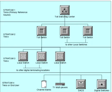
STRATUM 1
Telco (Primary Reference Source)
STRATUM 2 Telco
STRATUM 3 Telco
STRATUM 4 Telco or End User
Toll Switch Toll Switch Toll Switch
Toll Switching Center
Local Switch Local Switch Local Switch
to other Local Switches
to other digital terminating locations
Digital Switches DACS
Channel Banks
T1 Multi-plexers
Figure 1. Digital Network Hierarchy
When the Bell System was broken up into local service providers and long distance carriers, the timing hierarchy became less well defined. Following divestiture each local company could no longer take its timing from the long distance carrier; each had to engineer a system, a hierarchy or otherwise, to distribute timing within their own networks. This created new challenges whereby failures in the transmission systems could cause the creation of isolated areas that did not have reference to a Stratum Level 1 clocking source. In such cases, the isolated area is in holdover at whatever stratum level has been provided. Even if a particular network is still traceable to Stratum 1, the traffic of concern may be coming from an isolated area and will therefore slip at some rate. Having a Stratum Level 1 source within a network provides no guarantee that the results will yield a slip free network.
2.7 The Stratum Hierarchy
The ANSI T1-101 requirements for the various stratum levels are depicted in Table 1, which provides a comparison and summary of the drift and slip rates.
2.7.1 Stratum 1
Stratum Level 1 is defined as a completely autonomous timing source, which has no other input, other than perhaps a periodic calibration. The usual source of Stratum 1 timing is an atomic standard or reference oscillator. The minimum adjustable range and maximum drift is defined as a fractional frequency offset delta f/f of 1 x 10-11 or less. At this minimum level of accuracy, a properly calibrated source will provide bit-stream timing that will not slip relative to an absolute or perfect standard more often than once each 4 to 5 months. Atomic standards, such as cesium clocks, have much better performance than this requirement.
A Stratum Level 1 clock is an example of a Primary Reference Source (PRS) as defined in ANSI T1.101. Alternatively, a PRS source can be a clock system employing direct control from Coordinated Universal Time (UTC) frequency and time services, such as the Global Positioning System (GPS). The GPS is often used to provide high accuracy, low cost timing at a Stratum 1 level of quality. Commercial GPS receivers are widely used for this purpose.
2.7.2 Stratum 2
A Stratum Level 2 clock system tracks an input and holds to the last best estimate of the input reference frequency during impaired operating conditions. A Stratum 2 clock system requires a minimum adjustment range of 1.6 x 10⁻⁸. The drift of a Stratum 2 with no input reference is required to be less than 1.6 x 10⁻⁸ per year. The short-term drift of the system must be less than 1 x 10⁻¹⁰ in 24 hours. With a drift rate of 1 x 10⁻¹⁰ each 24 hours the cumulative effect amounts to 1 frame slip per 7 days. Commercial products for Stratum 2 clocks are available that offer a drift of less than 2.5 x 10⁻¹¹ per day, rendering a time interval to the first frame slip of more than 2 months.
2.7.3 Stratum 3
Stratum Level 3 is defined as a clock system that tracks an input as in Stratum 2, but over a wider range. A Stratum Level 3 clock system requires a minimum adjustment range of 4.6 x 10⁻⁶. The short-term drift of the system is required to be less than 3.7 x 10⁻⁷ per 24 hours. This amounts to approximately 255 frame slips in 24 hours. For this reason Stratum Level 3 clock equipment is generally not considered to be adequate to time SONET network elements.
2.7.4 Stratum 3E
Level 3 or better source. The drift with no input reference is required to be less than 1 x 10⁻⁸ per 24 hours. Commercial Stratum 3E systems are available that provide a drift
of less than 5 x 10⁻⁹ per 24 hours, exceeding the basic requirements for 3E
designation. This results in less than four frame slips per 24 hours, compared to 255 slips for Stratum Level 3. The typical commercial performance of these enhanced products is less than one slip in 36 hours or 9 x 10⁻¹⁰ per day.
2.7.5 Stratum 4
Stratum Level 4 is defined as a clock system that tracks an input, as in Stratum 2 or 3, except that the adjustment and drift range is 3.2 x 10⁻⁵. Additionally, a Stratum 4 clock has no holdover capability so in the absence of a reference it free runs within the adjustment range limits. The time between frame slips can be as brief as once per 4 seconds.
2.7.6 Stratum 4E
Stratum Level 4E has been proposed as a customer premises clock standard that supports a holdover characteristic that is not free running. This level, intended for use by Customer Provided Equipment (CPE) in extending their networks, has not been standardized.
Stratum
Accuracy, Adjustment Range
Pull-In-Range Stability
Time To First Frame Slip
1 1 x 10-11 N/A N/A 72 Days
2 1.6 x 10⁻⁸ Synchronizing accuracy of +/- 1.6 x 10⁻⁸ 1 x 10⁻¹⁰/day 7 Days
3E 4 x 10⁻⁷ 4.6 x 10⁻⁶ 5 x 10⁻⁹/day 7 Hours
3E 1.0 x 10⁻⁶ Synchronizing accuracy of +/- 4.6 x 10⁻⁶ 1 x 10⁻⁸/day 3.5 Hours 3 4.6 x 10⁻⁶ Synchronizing accuracy of +/- 4.6 x 10⁻⁶ 3.7 x 10⁻⁷/day 6 Minutes
4E 32 x 10-6 Synchronizing accuracy of +/- 32 x 10-6 Same as
Accuracy Unspecified
4 32 x 10-6 Synchronizing accuracy of +/- 32 x 10-6 Same as
Accuracy N/A
Table 1. ANSI T1.101 Stratum Clock Level Requirements
3 TELECOMMUNICATIONS NETWORK SYNCHRONIZATION
In the hierarchical source-receiver method a node with the most stable, robust clock is designated to serve as a source node. The source node transmits a timing reference to one or more receiver nodes. Receiver nodes are allowed to have equal or worse performance than the source node. The receiver node locks on to the timing reference of the source node and then passes the reference on to other receiver nodes. Timing is thereby distributed down in a hierarchy of nodes. Receiver nodes are usually designed to accept two or more references. One reference is designated to be active while all other references are designated as standby. In the case where the active reference is lost or is in error, the receiver node can switch references and lock to an alternate reference. Thus, each receiver node has access to timing from two or more sources. Most networks are engineered so that all receiver clocks are given two or more diverse references. In private networks, this may not be possible due to limited connectivity between nodes. Clocks are placed into the hierarchy based upon performance levels. ANSI T1.101 designates performance levels as Strata 1, 2, 3, 4E, and 4; ordered best to least accurate in performance. The International Telecommunications Union – Telecommunications Standardization Sector (ITU-T) Recommendation G.824, “The control of jitter and wander within digital networks which are based on the 1544 kbit/s Hierarchy” designates four performance levels: (1) PRS, (2) transit node, (3) local node, and (4) terminal or CPE node.
Primary
Stratum 1 or primary reference sources operate as the master nodes for a network. Stratum 2 or transit node clocks are most often used in toll switching and some digital cross-connect equipment. Stratum 3E is used for timing signal generators for use in SDH or SONET networks. Local switching, PBXs systems and T1 multiplexers have stratum 3 or local node clocks. T1 multiplexers, PBXs, channel banks, and echo cancellers may also incorporate some Stratum 4 or CPE clocks
3.1 Primary Reference Sources
A PRS is a master clock for a network that is able to maintain a frequency accuracy of better than 1 x10-11. One class of PRS is a Stratum 1 clock. A Stratum 1 clock, by definition, is a free running clock. It does not use a timing reference to derive or steer its timing. Stratum 1 clocks are usually comprised of an ensemble of Cesium atomic standards. However, a PRS does not need to be implemented by means of primary atomic standards. Both the GPS and LORAN-C clocks are examples of PRS. These systems use local rubidium or quartz oscillators that are steered by timing information obtained from GPS or LORAN-C. Although they are not considered to be Stratum Level 1 because they are steered, they are classified as PRSs. These clocks are able to maintain an accuracy within a few parts in 10-13 to a few parts in 10-12.r.ence
4 CARRIER NETWORKS
offset in relationship to the source clock. The frequency offset will accumulate in an environment consisting of a chain of clocks. Carrier networks are typically operated to ensure that accumulated frequency offsets do not exceed the required 1 x 10-11 accuracy. The major focus of synchronization for carriers is dominated by the receiver clock and the facility performance so the design of timing distribution and the selection of clocks and facilities used to time the network is of primary importance. The number and locations of the master clock nodes for the network are largely based on performance and maintenance considerations.
4.1 Carrier Network Synchronization Performance
The synchronization performance in a carrier network can be characterized by three components: (1) the accuracy of the master clock (2) the performance of the facilities distributing the reference and (3) the performance of the receiver clocks. Inaccuracies of the master clock usually contribute only a very small portion of the timing inaccuracies in a synchronization network. The performance of PRS clocks is usually 10-100 times better than the performance of receiver clocks. Synchronization performance, therefore, is dominated by the characteristics of the facility and receiver clock performance. During normal operations a receiver clock must lock to a source clock and extracting timing from a facility that has short disruptions or error bursts. The number of error burst events can range from an average of 1 to 100 events per day, depending on the facility type, distance, and other factors. These degradations adversely affect the distribution of the timing reference. The receiving clock will react to each error. It is allowed to move up to 1 microsecond in response to each error on its timing reference. The accumulation of facility errors and the corresponding phase error in the receiving clock can produce a receiver clock frequency inaccuracy range from a few parts in 10 -12 to a few parts in 10-10. Receiver clocks contribute a much larger portion of timing errors and slips in a network than the PRS.
4.2 Primary Reference Sources
Network topology determines where PRS clocks are used. PRSs are usually placed in locations to minimize the cascading of network timing. International switching locations are sites that also typically require the use of PRSs. In these locations two administrations interface with each other and all signals are transferred plesiochronously. These locations must operate within the 1 x10-11 frequency accuracy required for plesiochronous operation.
4.3 Interoffice Timing Distribution
The distribution of primary and secondary timing units throughout a network depends on the network topology and performance requirements. Interoffice timing is often configured so that the hierarchy is maintained, cascading is minimized, and performance requirements are achieved. Administrations may use traffic-bearing lines between offices to pass timing but some employ dedicated timing facilities between offices to improve the reliability, performance, and maintenance. Facilities with the best error performance, in terms of the lowest number of daily severely errored seconds and least downtime, are typically chosen to carry network synchronization. Error rates can often be attributed to the length of the facilities employed so short facilities are preferred. Satellite facilities are not used for timing distribution because of diurnal wander. References that are carried as traffic in Constant Bit Rate ATM, SDH, or SONET are also not used to carry the reference due to excessive wander. Most DS1/E1 references passed between locations are carried on facilities that use asynchronous multiplexing (e.g., DS3 multiplexing).
Asynchronous multiplexers use pulse-stuffing methods (see section 2.4) to transmit the reference without retiming or changing the long-term frequency of the signal. The inclusion of asynchronous multiplexing in the reference signal will not significantly affect synchronization performance so long as the jitter levels caused by the multiplexing remain controlled. The amount of reference cascading that can be allowed from the PRS to all other clocks in the network depends on the facility and clock performance objectives of the network. The design objective for most networks is 1 x 10-11 long-term frequency accuracy or 1 microsecond per day of timing inaccuracies. To achieve this level, BITS (see section 4.4) clocks must have rearrangement Maximum Time Interval Error (MTIE) performance of less than 1 microsecond, the facilities can contribute no more than a few errors per week, and timing cannot be cascaded to more than 4 offices. If very high quality BITS clocks and facilities are used, more cascading can be allowed and the number of required network PRSs is reduced.
4.4 Intraoffice Timing Distribution
requirements and the size of office. Stratum 2 and transit clocks are typically used in large toll offices, whereas stratum 3 or local clocks are used in smaller locations. If there is SONET or SDH equipment in the location, the BITS clock must usually be at least a stratum 3E or local clock, respectively. This is to minimize the number of pointer adjustment events occurring on the traffic passing through the SDH/SONET network. The most important performance parameter distinguishing clocks at the same stratum level is the MTIE. This parameter will have the greatest impact on daily performance of any function associated with the BITS clock.
4.5 Timing the BITS Clock
As described previously, the BITS clock requires two or more references from other locations. If dedicated facilities are used for timing the BITS clock, the facilities must terminate directly on the BITS. Alternatively, if traffic-bearing facilities are used, the reference facility that is chosen typically does not terminate on the BITS clock. Instead, a device called a bridging repeater is used. A bridging repeater is an in-line device that can tap onto any DS1/E1 signal and provide a copy of the signal. Using this method any traffic-bearing line coming into an office can be used as a timing reference for the BITS clock.
Digital
In order to receive timing that is not terminated on the clock, the BITS clock also requires external timing capabilities. External timing involves the use of ports on the device dedicated for synchronization purposes only. Some equipment, however, is limited to only being capable to extract timing from traffic that terminates on the equipment. If this type of equipment is selected for the BITS, and the reference line does not terminate on it, two or more traffic ports must be used for synchronization. Another factor that is very important in providing timing to the BITS clock is that diversity among the references must be maintained. Diversity is required at all levels in the hierarchy. The timing sources must be diverse, coming from a different locations and different equipment, over diverse facilities. In addition, power to all devices in the synchronization path, including facility multiplexers and bridging repeaters, should be also be diverse.
4.6 Timing Distribution from the BITS Clock
bridging repeaters can then supply timing (traceable to the BITS clock) to other clocks in the office.
Clock Distribution Units (CDU) are devices that accept a DS1/E1 reference and supply multiple references. They essentially perform like a multiplicative device giving multiple references out from one incoming reference. A clock distribution unit is distinguishable from a TSG in that the CDU does not include a clock and does not retime the line. It has no reference switching or holdover functions that are normally associated with a clock. If the input line to a CDU is lost, the CDU will cut off signals to all outgoing lines. The DS1/E1 BITS reference from the TSG, bridging repeater, or CDU is connected to the external timing input of all equipment in the location. Any equipment that does not have an external timing capability can receive timing directly from the BITS clock by either dedicating traffic ports for synchronization use only or by using a synchronous clock insertion unit (SCIU). An SCIU is a device whose only function is to reclock a DS1/E1 line that is passed through it. Other than reclocking, the SCIU does not affect the line being sent through it. By using an SCIU, BITS clocking can be injected on traffic-bearing lines and sent to equipment that does not have external timing.
A composite clock is an additional option to time equipment in a location. Namely, it is used to synchronize equipment that has DS0 interfaces, such as channel banks with DS0 dataports. The composite clock signal is a 64 KHz bipolar square wave with an 8 KHz signal riding on it in the form of a bipolar violation every 8 bits. Most TSG and CDUs will provide composite clock signals. Receiving equipment that uses composite clock signals requires only one timing reference.
4.7 Monitoring and Verification
A growing trend in telecommunications synchronization has been the use of monitoring systems to verify synchronization performance. The timing performance of an office can be verified by comparing the timing of a DS1/E1 line coming from that office with the timing from a well-known, highly-accurate reference. Monitoring can be done real-time and continuously by using a bridging repeater to tap into the DS1/E1 line and continuously measuring the line relative to a PRS. Verification is needed to detect and resolve timing degradations before they impact service. There are numerous sources of timing degradations including: (1) maintenance activities (2) circuit re-provisioning activity (3) clock diagnostics, and (4) excessive facility errors. These degradations are difficult to detect using standard alarm mechanisms. Monitoring provides the means for instant detection and simplified diagnostics of synchronization problems.
Switch Computer Counter
never passed as payload through an SDH/SONET facility. Instead, it recommends that timing is extracted from the optical signal. In this case, the timing is derived from the previous SDH/SONET network element in the facility. SDH and SONET also introduce additional restrictions because the BITS clocks in offices with SDH or SONET equipment must have at least a Stratum 3E or local clock in order to minimize the number of pointer adjustment events occurring.
5 YEAR 2000 (Y2K) CONSIDERATIONS
Date-related problems are not a new phenomenon for the telecommunications industry. Some digital switches, for example, in the past have had problems with billing tapes in leap years. In some cases, those problems appeared well before February 29th of the year in question. It is of great concern to telecommunications network providers that, if uncorrected, date-related problems could potentially result in the network not properly billing for calls. Thus, both providers and consumers have mutual interests in insuring reliable, uninterrupted services during the Y2K transition period.
In comparison to public carriers, private network operators present a slightly larger reason for concern because some may be counting exclusively on their suppliers to find and resolve all Y2K issues. While it is likely that large suppliers will find the majority of problems in their own equipment, many smaller providers may not have the resources necessary to validate that their equipment will interoperate with that of other suppliers' during the Y2K transition period. It is crucial that private network operators identify their interoperability risks as early as possible. It can be a significant undertaking to identify all of the ways in which date fields are used and exchanged by different systems within a large private network.
5.1 Global Positioning System Rollover
The NAVSTAR GPS is a system of satellites that allow the recipient to calculate time, location and velocity. The signals are sufficiently accurate to provide timing accuracy to within a millionth of a second, velocity within a fraction of a mile per hour and location to within a few meters.
5.2 Year 2000 Information and Readiness Disclosure Act of 1998
On October 19, 1998 the President signed into law the "Year 2000 Information and Readiness Disclosure Act of 1998;" also known as PL 105-271. This Act is intended to address concerns that have been raised regarding the potential for liability exposure resulting from Y2K information-sharing. The law is intended to provide protections to companies that respond responsibly and openly to Y2K readiness.
The Act provides that a federal entity, agency, or authority may expressly designate a request for the voluntary provision of information relating to year 2000 processing, including year 2000 statements, survey questions and results, implementation, verification and testing plans, as a special year 2000 data gathering request. Information submitted in response to a special Y2K data gathering request is provided certain protections under the Act. Additionally, the measure also extends certain antitrust protections and confidentiality protections to companies for providing the requested information. The Act generated such a deluge of questions to the private sector that concerns were raised that unless the government formed a centralized office to curtail the requests that it would require all of the available industry Y2K resources just to handle the questions; leaving no one available to actually correct he problems.
5.3 Industry Responds
By 1996 most major telecommunications firms within the United States began programs to identify and test systems for potential Y2K problems. An industry forum known as the “Telco Year 2000 Forum” began working in 1996 to address potential problems within the nations telecommunications systems. The forum is currently comprised of Ameritech, Bell Atlantic, BellSouth, Cincinnati Bell, GTE, SBC, Southern New England Telephone (SNET), and U.S. West. The year 2000 testing and evaluation is taking place at two levels. The first level, which is being conducted by the individual member companies, involves examination of individual network components or Network Entities (NEs). The second level is being coordinated, supervised, and conducted by Telcordia Technologies. Interoperability testing among the participants was completed as of December 22, 1998. The critical transition dates that were tested include: (1) December 31, 1999 to January 1, 2000 (2) February 28, 2000 to February 29, 2000, and (3) February 29, 2000 to March 1, 2000. Out of 1,914 test cases executed only six showed Y2K anomalies. None of these anomalies would have had an impact on call processing. All six problems were resolved and successfully retested. There were 32 cases that passed with non-Year 2000 findings that were referred to the product vendors
Wireless all of which are donating the use of laboratory facilities and staff resources. As of February 1999 ATIS announced that Y2K interoperability testing conducted by the IITC to date has indicated that there are no Y2K related anomalies within the U.S. interconnected telecommunications networks. ATIS conducted Y2K testing on a variety of areas including: call processing, mass calling events and potential congestion, cross network services involving credit card/calling card validation, toll-free service, rollover to Y2K in a local number portability environment, the impact of time zones, Government Emergency Telecommunications Service (GETS) and wireless to wireline call completion network impacts. The key dates tested were 12/31/99, 2/28/00, 2/29/00, and 12/31/00.
The nations major long distance carriers each have additional Y2K efforts under way to insure service continuity. Sprint has publicly posted a copy of their Securities and Exchange Commission (SEC) filing with respect to the companies’ Y2K status. Sprint is targeting Y2K compliance for critical applications to be complete by June 1999. With respect to testing, as of February 1999 Sprint indicated that approximately 79% of Network Elements, 85% of level 1 information systems applications has been tested, 41% of level 2 information systems applications have been tested, 95% of Sprint’s local network elements and 100% of both level 1 and level 2 local telecommunications division information systems applications have been tested. MCIWorldcom began Y2K efforts in 1996 and has a readiness timeline that provides for testing and monitoring activities to continue through the 4th quarter of 1999. Likewise, AT&T has contingency testing and certification plans that run through December 1999.
In short, the major long distance carriers have committed the resources necessary to insure a successful preparation and transition into the next millennium.
5.4 A Cautionary Note
It is clear that the U.S. telephone industry believes that it has sound plans to address Year 2000 issues. Furthermore, progress in executing these plans is so far, well advanced, and the projected schedule completion dates of mid-year 1999 appear realistic. Nevertheless, a degree of caution in assessing Y2K telecommunications systems compliance should be noted for a number of reasons. It is impossible, for example, to “certify” Y2K compliance of the public switch telephone network for a variety of reasons.
infrastructure for voice and data communications processing in the world resides in the hundreds of thousands of private networks distributed throughout the world. A Y2K failure occurring in these networks could preclude entry onto the Public Switched Telephone Network (PSTN), or could cause inconsistent performance during interactions with the PSTN. Within the United States many small, independent telephone companies provide services across the United States. The status and scheduling of their individual Y2K activities vary. Lastly, on an international level the degree of technical sophistication, network use, and Y2K readiness varies significantly on a country by country basis. The ability to predict smooth, consistent, seamless services across international boundaries is not possible at the present time, nor is there a single source of information or control to mandate that a global plan come together.
5.5 International Perspectives
A July of 1998 a study by Merrill Lynch & Co. in New York reported that half of the carriers in Brazil were in the “don’t know” if we will be ready category. Brazil’s Telebras was listed, by Merrill Lynch, as “woefully non-compliant at this stage.” Similarly, a study by British Telecommunications PLC found that only 11% of its interconnect partners in Africa and the Middle East were working toward compliance. Around the world so far information concerning the status of International Post Telephone and Telegraph (PTT) Y2K issues has been spotty and suggests very little uniform pattern or planning.
Fortunately, the major suppliers of equipment to the telecommunications industry worldwide appear to be well on their way to delivering compliant equipment to most PTT’s. Additionally, the International Telecommunications Union (ITU) established a Y2K Special Working Group to address international compliance. The ITU has begun a series of special working sessions to assess the status of international readiness for Y2K and to address how Y2K interoperability can be demonstrated around the world.
5.6 The Internet
Since the mid 1980’s the Internet has employed a standard known as the Network Time Protocol (NTP) for synchronizing network clocks using a set of distributed clients and servers. NTP is built on the User Datagram Protocol (UDP), which provides a connectionless transport mechanism. NTP evolved from the Time Protocol and the Internet Control Message Protocol (ICMP) Timestamp message.
mechanisms. NTP timestamps are represented as a 64-bit fixed-point number, in seconds relative to 0000 UTC on 1 January 1900. The first 32 bit contain the integer part and the last 32 bits contain the fractional part. NTP also supports a two-bit code warning of an impending leap-second to be inserted in the internationally coordinated standard time broadcasts. A leap-second is occasionally added or subtracted from standard time, which is based on atomic clocks. When necessary, the corrections are notified in advance and executed at the end of the last day of the month in which notified, usually June or December. When a correction is executed the first minute of the following day will have either 59 or 61 seconds. NTP also provides a mechanism to support a correction based on the estimated clock drift rate. This is a 32-bit signed fixed-point number indicating the estimated drift rate of the local clock. The value is dimensionless, with fraction point to the left of the high-order bit. The value can be either an estimate that is based on the hardware characteristics or it is also possible to compute the drift quite accurately.
The NTP hierarchy currently contains over 50 publicly accessible primary servers synchronized directly to UTC by radio, satellite or modem. The servers are conveniently located throughout North America, Europe and Asia. Generally, Internet client workstations and LAN servers with a relatively small number of clients do not need to synchronize with primary servers. There are about 100 publicly accessible secondary servers synchronized to the primary servers and capable of providing synchronization to a total in excess of 100,000 clients and servers distributed throughout the Internet.
The Simple Network Time Protocol (SNTP) is a simplified protocol access strategy for servers and clients deployed in the Internet. There are no changes to the protocol or implementations now running or likely to be implemented in the near future. The access paradigm is identical to the UDP/Time Protocol. SNTP implementations for personal computers are widely available within the Internet. With careful design and control of various network latencies it is possible to use SNTP to deliver time synchronization accurate to the order of microseconds.
In January 1999 an Internet Draft titled “The Internet and the Millennium Problem (2000)” was posted for review. It should be noted that Internet Drafts are draft documents that are valid for a maximum of 6 months. Drafts may be updated, replaced, or obsoleted by other documents at any time. The Internet Engineering Task Force (IETF) position on Internet Drafts is that it is not appropriate to use Internet Drafts as reference material or to cite them other than as a "working draft" or "work in progress".
protocols were given a clean bill of health. A few cases of 'period' problems were discovered where a time field would 'roll over' as the size of field was reached. In particular, there are several protocols that use 32 bit signed integer representations of the number of seconds since January 1, 1970. These will turn negative on Tuesday January 19 03:14:07 GMT 2038.
A problem exists with both RFC 977, Network News Transport Protocol (NNTP) and RFC 10336 the Usenet News Message Format, RFC 10336. Both specify a two-digit year format. An IETF working group has been formed to update the network news protocols. A similar two-digit year problem has also been discovered in RFC 1861, the Simple Network Paging Protocol Version 3 and RFC 1645 Simple Network Paging Protocol Version 2.
RFC 1507, Distributed Authentication Security Services (DASS) contains an expository discussion of time and secure time. It defines absolute time as an UTC time with a precision of 1 second, and discusses Abstract Syntax Notation 1 (ASN.1) time value encoding. The UTC time definition contains imprecisions that could create problems with implementations of the protocol.
Internet RFCs 1421 through 1424 specify that Privacy Enhanced Messaging (PEM) should use UTC time formats that could have a millennium issue since the year specification only provides the last two digits of the year. An important side note is that the Massachusetts Institute of Technology (MIT) reference implementation of Kerberos, sets the expiration of issued tickets to December 31, 1999 by default. Although this is not protocol related matter it could have operational impacts for MIT based kerberos implementation environments.
6 PRECISE TIME AND THE U.S. NAVAL OBSERVATORY MASTER
CLOCK
The U.S. Naval Observatory (USNO) is charged with the responsibility for precise time determination and the management of time dissemination within the United States. It has been officially recognized as the “country’s official timekeeper.” Modern electronic systems, including navigation and communications systems are increasingly dependent on precision timekeeping. Well know examples include the LORAN-C ground-based navigation system and the satellite-based GPS. These systems are based on the travel time of electromagnetic signals, which provides for an accuracy of 10 nanoseconds (10 one-billionths of a second) and corresponds to a position accuracy of 10 feet. Both the LORAN-C and GPS official systems are referenced to the USNO master clock.
USNO to compute a time scale that is not only reliable but also extremely stable. This system produces a clock rate does not change by more than about 100 picoseconds
(0.000 000 000 1 seconds) per day. On the basis of this computed time a clock reference system can be steered to produce clock signals that serve as the USNO Master Clock. The clock reference system is driven by a hydrogen maser atomic clock. Hydrogen masers are extremely stable clocks over short time periods (less than one week). Hydrogen masers provide the stability, reliability and accessibility needed to maintain the accuracy of the USNO master clock system.
6.1 Cesium Beam Atomic Clocks
A cesium-beam frequency standard, more commonly known as an atomic clock, is a device that uses the exact frequency of the microwave spectral line emitted by atoms of the metallic element cesium as a reference; in particular its isotope of atomic weight 133 (Cs-133). The integral of frequency is time, so the frequency 9,192,631,770 Hz provides the fundamental unit of time, which is measured by cesium clocks.
Today, cesium clocks measure frequency with an accuracy of 2 to 3 parts in 1014 Hz. This is equivalent to a time measurement accuracy of 2 nanoseconds per day or one second each 1,400,000 years. Thus far it is the most accurate realization of any kind of unit that mankind has yet achieved. A cesium clock operates by exposing cesium atoms to microwaves until they oscillate at one of their resonant frequencies and then by counting the corresponding cycles as a measure of time. The frequency involved is that of the energy absorbed from the incident photons when they excite the outermost electron in a cesium atom to transition from a lower to a higher orbit.
Quantum theory states that atoms can only exist in certain discrete quantized energy states depending on what orbits about their nuclei are occupied by their electrons. Although different types of transitions are possible those of interest involve a change in the electron and nuclear spin hyperfine energy level of the lowest set of orbits commonly known as the ground state. Cesium is the best choice of atom for this type of measurement because each of its 55 electrons, except the outermost, are confined to orbits in stable shells by electromagnetic force. Thus, the outermost electron is not disturbed by the others. Cesium atoms must be kept in a vacuum of approximately 10 trillionths of an atmosphere so that they are not affected by other particles. Under these conditions Cesium atoms will radiate in a narrow spectral line whose frequency can be accurately determined.
6.1.1 Kinds of Cesium Clocks
The U.S. Naval Observatory operates about 70 Cesium clocks and other precision clocks including 7-10 hydrogen masers. These Cesium clocks are distributed into 18 temperature and humidity controlled vaults. Special devices called time-interval counters are used to compare the time of each clock against the master clock. The frequency of the master clock is then steered toward the average of the other clocks. The resulting time is the USNO’s measure of UTC.
6.1.2 USNO Cesium Clock Characteristics
The USNO Cesium clocks have an accuracy of 1 x 10-12, a frequency stability of 8 parts in 10-14, and a time domain stability of < 2 x 10-14 .
7 CONCLUSIONS
The technology movement towards all digital high-speed synchronized networks has been under way for the past 30 years. The pace of change in the telecommunications infrastructure during the 1990’s has been particularly brisk. The breakup of the telecommunications monopoly structure in the United States during the 1980’s brought about significant changes to the structure and hierarchy of national digital networks, especially with respect to the timing and synchronization of public networks.
Today, the telecommunications infrastructure is much more diverse and robust. Whereas in the past a single company held the responsibility for the operation of the hierarchy of telecommunications clocking and synchronization systems, today most telecommunications administrations use their own hierarchical source-receiver method to synchronize their networks. The choice of where an administration derives a clocking source (e.g., LORAN-C, GPS, private Stratum 1 system) is determined on a carrier-by-carrier basis. A key-driving factor, especially for smaller telecommunications firms, is the cost. For this reason the USNO master clock has increased in importance with respect to its role in synchronizing parts of the nations telecommunications infrastructure.
unresolved Y2K issues cannot be satisfactorily resolved by a reliance on the testing of public carrier networks. Indeed, the major challenge faced by private networks is that not only should each timing and synchronization device be Y2K certified but that interoperability within the multivendor systems comprising the member agencies connectivity to public carrier networks also needs to be assured.
One means to be prepared for Y2K operational issues would be, in association with NCS Y2K contingency planning activities, to establish a central information collection and dissemination facility for Y2K operational issues. Such a center could provide the means for NCS member agencies to report Y2K related problems encountered within their private networks and/or interconnection to other networks and could also serve as a means for rapidly identifying cross-governmental issues in a manner similar to the procedures that have been established for reporting network intrusion and/or security advisories. For example, in December 1997, the National Security Telecommunications Advisory Committee (NSTAC) approved a recommendation that the NCC establish “an initial intrusion incident information processing pilot.” Today, a number of government funded activities (e.g., Computer Emergency Response Team (CERT)) exist for the purpose of electronically disseminating “early warning” notices with respect to operational deficiencies as they are discovered. A similar Y2K operational notification system for the NCS could prove to be beneficial. It may, for example, be feasible to supplement the already existing security notification systems to also report on Y2K problems encountered and vendor patch software releases. Over the next year it is reasonable to expect that some suppliers will release “last minute” software patches to correct Y2K related bugs. These patches may require rapid response action on the part of agency network operators to insure continuous operations. More importantly, vendors may rely on publication of available patches by means of their Internet web sites, which would require proactive action on the part of user agencies to “discover” that required software upgrades have been released.
REFERENCES
1. “Synchronizing Telecommunications Networks: Basic Concepts,”
Hewlett-Packard Application Note 1264-1.
2. “Telecommunications – Synchronization Interface Standard,” the American
National Standards Institute (ANSI) T1.101-1994.
3. ITU-T Recommendation G.824, “The Control of Within Digital Networks
which are Based on the 1544 Kb/s Hierarchies.”
4. 4 ITU-T Recommendation G.811, “Timing Requirements at the Output of
Primary Reference Clocks Suitable for Plesiochronous Operation of International Digital Links.”
5. “Clocks for the Synchronized Network: Common Generic Criteria,”
Bellcore Technical Advisory, TA-NWT_001244, Issue 2, November 1992.
6. J. E. Abate, et al, “AT&T’s New Approach to the Synchronization of
Telecommunication Networks,” IEEE Communications Magazine, Vol. 27, No. 4, April 1989.
7. “Synchronizing Telecommunications Networks: Synchronizing SDH and
SONET,” Hewlett-Packard Application Note 1264-2.
8. G. Garner, “Total Phase Accumulation in a Network of VT Islands for Various Levels of Clock Noise,” Contribution to ANSI T1X1.3, Number 94-094, September, 1994.
9. European Telecommunication Standards, “The Control of Jitter and Wander Within Synchronization Networks,” Draft ETS DE/TM-3017.
10. Federal Standard 1037C, “Glossary of Telecommunications Terms, August 7, 1996.
11. “Synchronizing Telecommunications Networks: Fundamentals of
Synchronization Planning,” Hewlett Packard Application Note 1264-3.
12. Philip J. Nesser II, “The Internet and the Millennium Problem (2000), Internet Draft dated January 1999.
13. A. Gerald Roth, Vice President - Technology Programs,
GTE Technology and Systems On Behalf of the Telco Year 2000 Forum, Testimony Before the House Committee on Banking and Financial
14. D. Mills, “Simple Network Time Protocol (SNMP),” Internet Request For Comments 1769, March 1995.
15. D. Mills, “Network Time Protocol,” Internet Request For Comments 1059, July 1988.
16. IEEE-SA Standards Board, IEEE Computer Society, “IEEE Standard for Year
ACRONYMS
ANSI American National Standards Institute
ASN.1 Abstract Syntax Notation 1
ATIS Alliance for Telecommunications Industry Solutions
BITS Building Integrated Timing Supply
CERT Computer Emergency Response Team
CDU Clock Distribution Units
CPE Customer Provided Equipment
DASS Distributed Authentication Security Services
E.O. Executive Order
EOP Executive Office of the President
GETS Government Emergency Telecommunications Service
GPS Global Positioning System
ICD Interface Control Document
ICMP Internet Control Message Protocol
IETF Internet Engineering Task Force
IITC Internetwork Interoperability Test Coordination
ITU International Telecommunications Union
ITU-T International Telecommunications Union - Telecommunications
Standardization Sector
MIT Massachusetts Institute of Technology
MTIE Maximum Time Interval Error
N6 Technology and Standards
NCS National Communications System
NE Network Entities
NNTP Network News Transport Protocol
NS/EP National Security and Emergency Preparedness
NSTAC National Security Telecommunications Advisory Committee
NTP Network Time Protocol
OMNCS Office of the Manager, National Communications System
PEM Privacy Enhanced Messaging
PRS Primary Reference Source
PSTN Public Switched Telephone Network
RFC Request for Comments
SEC Securities and Exchange Commission
SDH Synchronous Digital Hierarchy
SNET Southern New England Telephone
SNTP Simple Network Time Protocol
SONET Synchronous Optical Network
TSG Timing Signal Generator
UDP User Datagram Protocol
USNO United States Naval Observatory
UTC Coordinated Universal Time