Open GIS Consortium
35 Main Street, Suite 5 Wayland, MA 01778 Telephone: +1-508-655-5858
Facsimile: +1-508-655-2237 Editors: Tom Strickland
Cindy Strickland Telephone: +1 256.430.1718
[email protected] [email protected]
The OpenGIS™ Abstract Specification
Topic D1: Telecommunications Domain
Version 1
Copyright © 2001, Open GIS Consortium, Inc.
NOTICE
The information contained in this document is subject to change without notice.
The material in this document details an Open GIS Consortium (OGC) specification in accordance with the license and notice set forth on this page. This document does not represent a commitment to implement any portion of this specification in any companies’ products.
While the information in this publication is beleived to be accurate, the Open GIS Consortium makes no warranty of any kind with regard to this material including but not limited to the implied warranties of merchantability and fitness for a particular purpose. The Open GIS Consortium shall not be liable for errors contained herein or for incidental or consequential damages in connection with the furnishing, performance or use of this material. The information contained in this document is subject to change without notice.
The Open GIS Consortium is and shall at all times be the sole entity that may authorize developers, suppliers and sellers of computer software to use certification marks, trademarks, or other special designations to indicate compliance with these materials.
This document contains information which is protected by copyright. All Rights Reserved. Except as otherwise provided herein, no part of this work may be reproduced or used in any form or by any means (graphic, electronic, or mechanical including photocopying, recording, taping, or information storage and retrieval systems) without the permission of the copyright owner. All copies of this document must include the copyright and other information contained on this page.
Revision History
Date
Description
1/31/2000 Initial Release
Table of Contents
1. Introduction... 1
1.1. The Abstract Specification... 1
1.2. Introduction to Telecommunications SIG ... 1
1.2.1. References for Section 1 ... 1
2. The Essential Model for Telecommunications ... 2
2.1. Objects ... 2
2.1.1. Network Component Behaviors... 3
2.1.2. Relationships between the Features ... 3
2.1.3. WORK FLOW OBJECTS ... 3
2.1.4. ACTORS... 4
2.1.5. USER BEHAVIORS... 5
2.1.6. ARTIFACTS ... 6
2.1.7. References for Section 2 ... 6
3. Abstract Model for Telecommunications ... 7
3.1. Feature Geometry ... 7
3.1.1. Reference for Section 3.1: ... 7
3.2. Spatial Reference Systems ... 7
3.2.1. Reference for Section 3.2: ... 7
3.3. Location Geometry Structures ... 8
3.3.1. Reference for Section 3.3: ... 8
3.4. Stored Functions and Interpolation ... 8
3.4.1. References for Section 3.4 ... 8
3.5. Features ... 8
3.5.1. References for Section 3.5 ... 12
3.6. The Coverage Type... 12
3.7. The Earth Imagery Case ... 12
3.8. Relationships Between Features ... 12
3.8.1. Reference for section 3.8 ... 14
3.9. Quality ... 14
3.10. Feature Collections... 14
3.11. Metadata ... 15
3.12. Service Architecture... 15
3.13. Catalogs ... 15
3.14. Semantics and Information Communities ... 15
3.14.1. References for Section 3.14 ... 15
3.15. Image Exploitation Services ... 16
3.16. Image Coordinate Transformation Services... 16
4. Future Work... 17
5. Appendix A. Acronyms and Glossary... 18
1. Introduction
1.1. The Abstract Specification
The purpose of the Abstract Specification is to create and document a conceptual model sufficient to allow for the creation of Implementation Specifications. The Abstract Specification consists of two models derived from the Syntropy object analysis and design methodology [1].
The first and simpler model is called the Essential Model and its purpose is to establish the conceptual linkage of the software or system design to the real world. The Essential Model is a description of how the world works (or should work).
The second model, the meat of the Abstract Specification, is the Abstract Model that defines the eventual software system in an implementation neutral manner. The Abstract Model is a description of how software should work. The Abstract Model represents a compromise between the paradigms of the intended target implementation environments.
The Abstract Specification is organized into separate topic volumes in order to manage the complexity of the subject matter and to assist parallel development of work items by different Working Groups of the OGC Technical Committee. The topics are, in reality, dependent upon one another each one begging to be written first. Each topic must be read in the context of the entire Abstract Specification.
The topic volumes are not all written at the same level of detail. Some are mature, and are the basis for Requests for Proposal (RFP). Others are immature, and require additional specification before RFPs can be issued. The level of maturity of a topic reflects the level of understanding and discussion occurring within the Technical Committee. Refer to the OGC Technical Committee Policies and Procedures [2] and Technology Development Process [3] documents for more information on the OGC OpenGIS™ standards development process.
Refer to Topic Volume 0: Abstract Specification Overview [4] for an introduction to all of the topic volumes comprising the Abstract Specification and for editorial guidance, rules and etiquette for authors (and readers) of OGC specifications.
1.2. Introduction to Telecommunications SIG
The Special Interest Group (SIG) for the Telecommunications Domain of OGC proposes this document to enumerate the requirements of telcos. Telcos, in this paper are defined as Communications Service Providers. These may be Incumbent or Competitive local exchange carriers (ILEC or CLEC), Long distance providers, or Wireless providers. The basic definition of objects, relationships, and actors are defined in Section 2.
Section 3 is a companion to the OpenGIS bookshelf. In this section, one subsection relates to the Abstract Specification Topic Volume. The reader is directed to read this as a companion to the other documents of the Consortium and, at a minimum, the Abstract Specification Overview [4].
1.2.1. References for Section 1
[1] Cook, Steve, and John Daniels, Designing Objects Systems: Object-Oriented Modeling with Syntropy, Prentice Hall, New York, 1994, xx + 389 pp.
[2] Open GIS Consortium, 1997. OGC Technical Committee Policies and Procedures, Wayland, Massachusetts. Available via the WWW as <http://www.opengis.org/techno/development.htm>. [3] Open GIS Consortium, 1997. The OGC Technical Committee Technology Development Process,
Wayland, Massachusetts. Available via the WWW as <http://www.opengis.org/techno/development.htm>.
2. The Essential Model for Telecommunications
The purpose of an essential model for the telecom domain is: (1) to improve productivity of engineering staff,
(2) provide tools to speed up provisioning process, and
(3) provide easy access of network information to end users, within the domain of the outside plant network.
The objects of interest in this environment include GIS-oriented items such as streets, political and service area boundaries, hydrography, parcels, and customer locations. The AM/FM system extends these with various new network features that tend to be more complex than many other types of GIS features including:
2.1. Objects
Structures-Supports, contains, or houses other objects. Examples are poles, manholes, pedestals, towers, and conduit. (Conduit may also be considered a conductor of sorts.) Bridges, dams, or tunnels may also be structures for supporting devices and cables. Buildings, such as Central Office, are also structures.
Attachments-Items associated with or attached to structures. Examples are guys, anchors, other utility items (CATV or electric).
Conductors-Carry signal and include copper, fiber, coax, and specific frequencies for wireless. The AM/FM model depicts sheaths graphically and maintains a much finer granularity of the internal conductors, which for copper are referred to as pairs and in fiber are strands. Additional information per strand or coax sheath may include frequency ranges and assignments.
Devices-Launch, extract, monitor, amplify, or change signal at points in the network. These include multiplexors, terminals, splitters, network interface devices (NID/NIU), etc. Typically, devices contain multiple ports for connecting to other devices or conductors. These devices may be further subdivided into various groupings based on such characteristics as whether or not they are power consuming (which tends to add noise or distortion to the signal versus simply lowering signal strength if passive). If they are field configured via sub-devices (cards into slots), they may be thought of as component objects. A special class of device, the switch, may be dealt with as a completely different object because of its complexity. Customer premise equipment, such as telephones, PBX, routers, gateways, etc., are also devices (and have associated conductors which may be known to the network).
Locations-Special points of interest on the network. Locations may include markers (call before you dig), ground points, splice points (which may be classed as pseudo-devices), etc.
Of particular interest to the model are “customers”. These objects may not include a direct spatial coordinate, but may be geographically located through the “street” objects. They may also be identified on parcel maps or other geographic models. Each feature in a telephone model can be classified as one of the above or will be a standard GIS feature such as a street, landmark, parcel, etc.
Each of these features optionally contains associated attributes. These attributes may be organized into multiple aggregates in various ways. One approach lists these by usage or type as:
• Accounting or CPR (continuing property records)
• Engineering (signal capacity and side effects, structural, size, and materials) • Identity (for the feature itself and to identify its designer, job numbers, an dates) • Location (spatial, serving area(route), map plat sheet, address)
For telecommunications, all features will have identity and location. Some, however, may not be of interest to accounting or may not have engineering significance (defined per feature class). Relationships also may not be defined for every type of feature.
2.1.1. Network Component Behaviors
Network components also have behaviors that model their real world objects.
Conducts signal-Conductors and devices conduct the signal (and may modify the type of signal). Signal types (lightwaves, as an example) can only be conducted on certain conductors and devices (optical fiber). Therefore, only certain items may be connected together to provide connectivity. Provides customer access-Network interface devices as well as their “feeding” conductors and devices are identifiable as providing access to a customer.
Wears out-Network components are carefully monitored to determine their effective life span, both for amortization and proactive maintenance. Dates of deactivation and/or removal are maintained with the feature, even if its geographic location (i.e. landfill) is no longer needed.
Gets broken-removal or replacement is tracked as well for items whose life is prematurely ended. Needs permit-placement of items in an area, as part of a work order, may require government authorization.
Has capacity-Devices may be configurable with minimal, maximum, and increment capacity. These values, as well as current capacity are important information to maintain. Conductors should not carry this information.
2.1.2. Relationships between the Features
Particular relationships that are of interest in an AM/FM model include:
Connects to-Relates devices to devices or conductors, attachments to structures, and conductors to other conductors or devices. This relationship may be considered the same in either direction. For example, if a connects to b, then b connect to a. It should be noted that a graphical intersection does not imply ‘connects to’. If cable “a” crosses conductor ”b”, without some splice or device to create a physical connection, then “a” does not connect to “b”.
Feeds-Provides signal to, has a corollary in the relation’s “ fed by”.
Additional information is needed to know if “a” feeds “b”, whether “b” also feeds “a”. In other words, this relation may be uni- or bi-directional. (This relation is typically not graphically depicted, because it occurs within the internal definition of the device port or conductor strand rather than at the housing or sheath level.) A special instance of “feeds” may be referred to as “serve(s),” as in the case of which terminal serves this customer “or” what transmitters serve this area.
Houses or contains- (may be referred to as supports or enclosures)-Relates structures to conductors or devices. A pole tends to support various devices and conductors, to provide a location for the item in the same manner in which a manhole or pedestal encloses the conductor or device. For example, pole ”a” contains splitter “p” and tap”q”; duct “r” innerduct “b” contains conductors “c” and “d”.
2.1.3. WORK FLOW OBJECTS
In addition to the physical network, tools, and landbase items, the organizational objects are critical to the information system flow for dealing with creation and maintenance of the network. These include:
Work package (WP)-Contains work prints which provide the locations for modifications and the details of the work to be performed (such as splice details) as well as the Bill of Materials (BOM) of items need to perform the job and possibly the economic or other justification for the work to be performed.
Trouble reports (TR)-Reference items of plant, typically a customer premise device, at which signal is weak, noisy, or missing. From this initial definition, the problem is tracked to a device or point along a conductor where a fault occurs. Due to planned redundancy, a separate route (or strand or pair) may be used to provide an immediate solution. However, the TR, with the detail problem description, may become an AM/FM object associated with the device or conductor until it is repaired or replaced.
Forecasts, evolution plan, and capital budget-future plans that can affect the on-going engineering decision process.
Of course, many other “non-geographic” systems relate to the AM/FM/GIS system. These include customer systems that track usage and billing, assignment systems that relate phone numbers and services to specific devices and frequencies, operations systems that provide real-time switching and monitoring, inventory reporting, and payroll systems.
2.1.4. ACTORS
Many different job functions must be performed in this domain, by the following users: Engineers-Analyze the signal levels and proposes short-term modifications to the model. Incorporate the Planner’s long term plan into short-term modifications (jobs or work orders). Planners-Engineers who analyze utilization versus capacity, problem areas, growth areas, forecasts, and propose changes to be made to the network by year, over several years. Forecasters-Evaluate demographics and competition presence to estimate growth trends for geographic areas.
Customer service-Examines capacity and assigns signal (may involve an assignment actor) to specific customers, both for new orders and as a response to problems.
Construction-uses the engineering proposals to place, remove, or modify physical facilities. Deviations from the proposal are communicated to engineering for additional analysis and model update, including “transitioning” planned features to as-built ones.
Material manager-Maintains inventory of devices, structures, and conductors to support creation and maintenance of network.
Inspectors-Monitor the construction for conformance to safety and design/plan, and test the constructed model to determine whether the model operates as the engineering analysis indicated it should. If not, problems are identified and corrected. Actual signal (and in cases power) levels are input to the AM/FM model.
Cartographers-Collect and maintain landbase information for streets, right of ways, customer locations, and other physical and political features of interest.
Accountants-Track equipment in use, abandoned in place, or removed to determine life expectancy (amortization costs) as well as installation and maintenance costs of providing service. They additionally may use spatial analysis to determine facilities within boundaries for tax reporting purposes.
Marketing-Determines capacity and capabilities of the network in relation to customers and prospects in order to offer additional services. They identify areas where services could be sold for expansion.
Installers/repair-Determine where to acquire signal to serve customers. They may compare various test levels to expected (analyzed) levels to identify faulty components or splices.
Locators-Need to determine where facilities exist in order to provide the appropriate level of support (marking of routes, all clear, etc.) to construction in an area.
Management-Needs to be able to determine where excessive repairs or growth are occurring, where lack of growth may indicate competitive encroachment, where costs are above or below norms for similar activities, and other related information.
IT/IS-Needs to integrate other software, establishes rules, and adds manufacturer information. Data base administration-Set up security, establish procedures, and distribute software.
CLEC’s (Competitive Local Exchange Carriers)-may request and must be provided information about location and types of facilities. The ILEC (Incumbent…) may be required by law (such as the US Telecommunication Act of 1996) to offer CLECs use of facilities to foster competition. Other utilities and Government agencies-both provide and require information about planned construction (especially underground or roadwork) which will need to be coordinated in order to maintain infrastructure.
Legacy systems-Any existing software system in a telco which provides or receives information in the process of modification of the AM/FM/GIS model.
2.1.5. USER BEHAVIORS
In order to perform their jobs, users must perform certain operations with model data. The model components also exhibit certain behaviors that mirror the way users operate in the current work place.
Locate-Based on an address, a facility id (terminal or pole), or a route, a user queries the model to geographically position a view of the model. Based on an extent or trace of the network from that point, the user will determine the extent of the information desired. During locate and subsequent manipulation, a user’s view of data may need to change depending on the extent of the area to be viewed. For instance, when viewing 20 square miles, details of alleys, right of ways (ROW), and connectivity are useless clutter, while these are important when viewing a city block.
Produce relevant representation-The user needs to filter out irrelevant information for the job being performed. Remaining information may need to have certain items emphasized while minimizing other aspects of the model to support the job. These user views are definable and tend to be reused.
Analyze the problem-Depending on the job to be performed, the analysis may be distance from a location (locate or marketing), facilities in an area (tax), or signal levels at a point (engineering, trouble).
Input information-The user may input an analysis point, area, or propose modification and addition of facilities.
Design a Solution-For planned or proposed modifications, the user will analyze the effects of the modifications on the network in the area.
Verify Design-The results of the analysis from one or more proposals will be evaluated to ensure adequacy of the design.
Estimate costs-Produce a Bill of Materials (BOM) with item costs and labor estimates for placement, removal, splicing, etc. to evaluate costs.
Prepare work package-The work package includes source packages (such as trouble reports or customer requests) and specially formulated output print(s) of the work to be performed, BOM, and analysis reports.
Update master-Updates to the model typically include certain “what if” scenarios so that changes are deferred until a definitive plan is approved. After construction, the model is updated with information as to when the plan was constructed (and later activated), as well as any plan deviations. This final transaction is applied to the model.
2.1.6. ARTIFACTS
Users need or expect certain tools to perform their actions with or on the model. Some relate to their use of earlier paper records, while others relate to tools in the field. For instance, the user needs to measure distances, magnify the view of the area, read signal levels, (as in using an OTDR) at a point, and apply “engineering table” values to conductors and devices existing or added to the network. Because of this, certain operations or methods are expected to exist in the model. These are typically known as “artifacts’ or user interface objects. The user uses the artifacts to interface with the abstract model and uses the output from the model to interface with the real world.
Locate facility-Find an address or facility location in geo-space with a query based on a real world value.
Measure distance-May mean line-of-sight distance between points or it may mean measure conductors between two devices. The latter includes lengths not geographically indicated, such as the inclusion of sag and coils, which are known in the conductor objects.
Measure signal levels-at a point-Trace the internal strands or pairs and devices to a launch point where signal values are known and compute dB loss, attenuation, noise, power, or distortion values based on lengths and types of conductors and details on every device back to that point.
Scale-Due to congestion in an area, device and annotation display may be reset from a value of 1”=100’ to 1”=50’ while linear features remain unchanged in presentation. (Note: utility feature presentation is typically exaggerated, such that a 15” diameter pole may cover 10’ of ground space pictorially, depending on scale. Textual annotation of engineering detail is exaggerated.)
BOM-Aggregate features associated with the work order for addition, modification, or removal for automated BOM generation to communicate with construction and material management as well as costing modules.
Work Print-For communications to construction, engineers require the ability to prepare a work package that includes graphic prints or plots. This will typically consist of multiple geographic sheets which may overlap or be disjointed in addition to schematic and detail drawings showing internal connections and routing (as in duct banks inside manholes or fiber strand connections for devices). Output presentation will exaggerate modifications while ghosting existing facilities to clarify work to be performed.
Drafting tools-Built into feature placement and edit with options like “copy parallel”.
Engineering charts-Built into the rules automatically, as well as in help and manufacturing tables, in order to establish values at time of placement and/or be used during calculations.
Engineering work sheets-Setup face sheets (for work or job orders) which contain management data, that is used to automatically annotate work print borders and associate group information with facilities.
Blueprints-Associate with (typically predefined) detailed drawings.
Magnifying glasses-Zoom, view, and window (dynamic scroll/pan) commands.
2.1.7. References for Section 2
3. Abstract Model for Telecommunications
3.1. Feature Geometry
The spatial geometry model as defined would serve as a complete definition for areas of telecommunication considered by the Telco SIG. In wireline models, the 2d representation and methods defined provide for most existing geospatial representations or telco models in existence or under development. Telco models do have positionally anchored annotation paragraphs or text which are oriented to provide clarity of definition of the feature being described while avoiding overstrike or juxtaposition problems with facilities. Although the geometry model ignores this item, the geometric constructs could be utilized to describe the location and orientation for presentation, without losing existing “cartographic positioning” of what will be described under the presentation area of this paper.
The 3d-model definition or the association with TIN where the TIN included elevation would serve the wireless areas of Telco in the evaluation of line-of-sight evaluations for tower spotting and coverage allocation.
The option to include a Topologically association with the Geometric association while not mandating its existence supports either the creation of this as an index to respond to spatial requests of the model or to the maintenance of this topologic association during editing operations. Graph Theory, (Feature Geometry Doc. 99-101, Section 3.6.12), and states:
A simple graph theory package for the applications needing a shortest path algorithms combines functionality from 1D Simple Topology and the basic geometry packages. The existence and usage of this topology implementation which could support sheath or conduit trace does not prohibit the definition of graph theory implementations to support network traversal. Further, it does not replace the need for this definition to address the connectivity, which is not shown in a geospatial model.
Association of multiple geometric definitions with a Telco feature will be discussed in the feature section of this document.
3.1.1. Reference for Section 3.1:
[1] OpenGIS™ Abstract Specification, OpenGIS™ Project Documents 99-101, available through www as <http://www.opengis.org/techno/specs.htm>.
3.2. Spatial Reference Systems
The classes defined and capabilities described are endorsed by the Telco SIG as being sufficient to deal with the GeoSpatial Referenced models in place and under development by the
Telecommunications industry. In addition to the SRS list included with WKS, Telcos use a SRS known as Horizontal & Vertical. This is widely used where Common Language Location
Identifiers (CLLI) are deployed (refer to ANSI T1.253-1996 for additional information)).. In general practice, each H&V associated facility item also has a Longitude and Latitude (although without fractional seconds) associated with it.
3.2.1. Reference for Section 3.2:
[1] OpenGIS™ Abstract Specification, OpenGIS™ Project Documents 99-102r1.doc, available through www as <http://www.opengis.org/techno/specs.htm>.
3.3. Location Geometry Structures
The classes defined and capabilities described are endorsed by the Telco SIG as being sufficient to deal with the models in place and under development by the Telecommunications industry. For vector models, the existing WKS is adequate in almost all cases.
3.3.1. Reference for Section 3.3:
[1] OpenGIS™ Abstract Specification, OpenGIS™ Project Documents 99-103.doc, available through www as <http://www.opengis.org/techno/specs.htm>.
3.4. Stored Functions and Interpolation
Stored functions as described are beneficial to the Telco domain. Additional functions, also important to this domain would include optical versus sheath distance measurements. In explanation, an OTDR (Optical Time Domain Reflectometer) is attached to an optical strand in a circuit. It may indicate a loss of reflectivity 8479 meters along this circuit. The telco needs to instruct a crew to dig up the sheath and repair the damage. However, the sheath as shown of the geospatial display does not include distances of the fiber in loops or coils within manholes or handholds along the route. The geospatially measured distance would also not consider the internal wrapping of the bundles of fiber within the sheath which (depending on being an inner or outer bundle) can introduce more than 2 meters difference over a kilometer. A telco interpolation function would utilize true sheath distances and bundle wrap factors associated with the strands traversed to provide a computed geospatial location along the appropriate sheath at the optical distance of the reported 8479 meters, although a geospatial measurement of the associated sheaths to that point might be anywhere between 6 and 9 kilometers.
Many additional stored functions could be identified. These are generally outside the interest of typical geospatial systems.
3.4.1. References for Section 3.4
[1] OpenGIS™ Abstract Specification, OpenGIS™ Project Documents 99-104.doc, available through www as <http://www.opengis.org/techno/specs.htm>.
[2] Newton’s Telecom Dictionary: The Official Dictionary of Telecommunications and the Internet. Fifteenth Updated, Expanded Edition. Copyright 1999-Harry Newton. Miller Freeman, Inc. publisher
.
3.5. Features
Section 2.1 states “Geospatial information has one purpose: to communicate knowledge about things that have “whereness.” The knowledge imparted by the map answers two kinds of questions: “where” and “what.” Maps can tell us where things are, both in relation to other nearby things and in relation to abstract coordinate systems. Maps also can tell us what things are, either through symbology (e.g., by use of color or line pattern whose meaning is explained in a legend) or through text or tabular annotations or multi-media links. The same goes for attributes that modify or extend our knowledge of things.”
between two poles includes sag and varies based on temperature and metallic composition. Although a cable length is always more than the sum of the pole spans it traverses, the “fit” of the dimensional definition within geospatial is true, even though meaningless (or at best erroneous) for signal calculations.
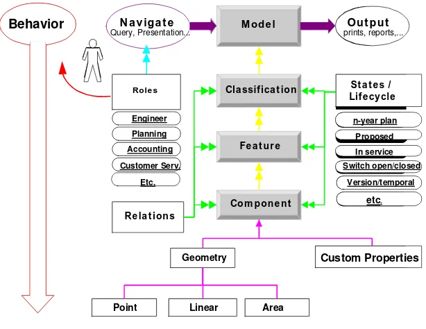
In 2.73. Project World Feature Instances states, “This specification is intended to enable the geospatial engineer to conceptualize and model features in a manner appropriate to the task at hand, and does prejudice the engineer with predefined thematic classes.” Thematic classes and features themselves are abstracted differently within a telecommunications model as explained in STRICK99, [Proceeding of the 1999 GITA Conference, Enterprise Integration of Intelligent Business Objects, Tom Strickland, Byers Engineering Company]. A slide from this presentation is shown as figure 3.5.1.
Com pone nt
M od e l
Cla ssifica t io n
N a v iga t e
Query, Presentation... prints, reports,...Ou t p u t
Custom Properties
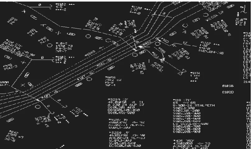
Figure 3.5.2 Telecommunications Distribution Model
Note also in Figure 3.5.2 the large quantity of specialized symbols that indicate splices, terminals, manholes, foreign poles, and other telco features. This figure also shows the large amount of textual annotation, much of which exists to quickly identify the connectivity arrangement of the conductors shown to describe the internal definitions within the shown sheaths or cables. Feature collections are referenced in section 2 of this paper in the description of work orders as a group or collection of all design and word performed as a result of a single authorization. Collection as defined in the Feature document (2.10.3) includes the common practice of subdividing cable geometry into segments in tiles for a single cable.
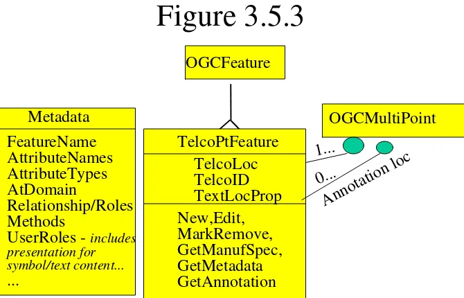
Figure 3.5.3
Note: Any OGC geometry type may be used to show
text location. 0 references = dynamic text
ANSI standard T1.253 has already been referenced as a naming standard for telecommunications equipment, structures, or even customers. In addition to this code, many features include their support structures for identity. Thus, most devices and conductors may be located via their “lead & structure” identity. Lead in this case is the route number from the feeding switch or device. Most Identity structures include a device and card barcode or equipment id, as well as a unique serial number. These identities typically are augmented with identities associated with their model and the model has identity. In some cases, the tiles of the models have identity. These identities are persistent and immutable. They are used for relationships not only within this model but may also be repeated in other legacy systems, models of other infrastructure suppliers (such as CATV or Electric) and even in competitor models.
In most cases, identity is a local definition. True unambiguous uniqueness requires multiple properties or attributes, which may include Company, wire-center, tile, local unique id. Conductors may require two of these identities, in that rather than maintaining their own identity (other than strand, gauge…) they contain the identity of the device (or splice) at either end of their containing sheath.
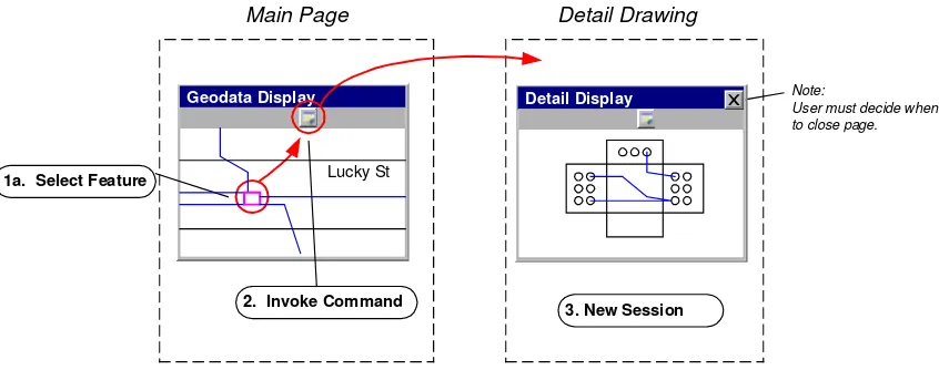
2. Invoke Command
Main Page Detail Drawing
Geodata Display
1a. Select Feature
3. New Session
Note:
User must decide when to close page.
Detail Display
Lucky St
Figure 3.5.4 Two instances of a single Manhole feature.
In section 2.15 discussion of creation of identifiers during edit is discussed. Due to the need to edit or modify facilities in telecommunications models, many different approaches to this problem have been implemented in digital models. In every case uniqueness within a scope where the larger scope values are prepended are associated is the method employed. In the aforementioned ANSI T1.253, an agent or organization is identified to coordinate and ensure uniqueness. This group receives a request for a unique identity, where a proposed “dirty identity” is provided. If this is not unique, the agent is responsible for providing a different, guaranteed unique id within two business days.
In other digital systems, an editing session may request a number of unique identities, prior to starting the edit process. If the session does not use all of the “reserved” identities, these may be returned as the edits are incorporated back into a central model via a long transaction.
Alternatively, these unused ids, may simply be lost. Given a sufficient supply of unique values, this last approach is acceptable. If a user who has requested a set of unique ids uses them all, they are typically stopped from creating additional features until a new request can be processed from the unique authority. In most systems, which deploy this approach, the refresh of additional uniques may be requested transparently by the software, such that the user is never aware of the action.
In a similar vein, this industry has created many different implementations of both pessimistic and optimistic long transaction concurrency control. These along with the approaches to versioning and conflict resolution should be defined as examples for other areas and consideration for the
definition of a “proper long transaction protocol” as requested in 2.15.15. This belongs in future work for the Telco SIG.
3.5.1. References for Section 3.5
[1] OpenGIS™ Abstract Specification, OpenGIS™ Project Documents 99-105r2.doc, available through www as <http://www.opengis.org/techno/specs.htm>.
.
3.6. The Coverage Type
TBD3.7. The Earth Imagery Case
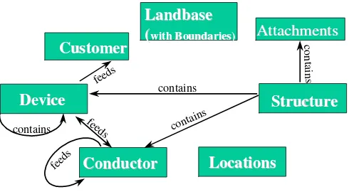
TBDRelationships within a Telco model are dependant on the features defined for that model. Based on the set of features defined in section 2, which are somewhat generalized or grouped to indicate sets of functionality. One implementation of this can be shown as in figure 3.8.1.
(
with Boundaries)with Boundaries)Device
Figure 3.8.1 Features with Relationships
This figure simplifies relationships to only two named relationships: Feeds and Contains. It is easy to argue that this representation obscures sheath and housing. Because of this the “connects to” relationship is omitted. As a result, the structure grouping could be inferred to contain sheath or trench, or even both if structure added the relationship to contain other structures.
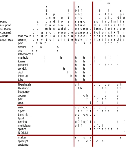
It can also be argued that contains is not sufficient to define the relationship between a CATV cable and a pole or a guy wire and a pole. Obviously, in the real world a pole does not contain these items. Instead there is a “support” named relationship that is required. A more detailed, but arguably still incomplete set of features and relationships for a wired Telco model in shown in the spreadsheet in figure 3.8.2.
Figure 3.8.2 Feature Relationships
3.8.1. Reference for section 3.8
Open GIS Project Document Relationships Between Features (99-108r2.doc).
3.9. Quality
TBD3.10. Feature
Collections
3.11.
Metadata
TBD3.12.
Service Architecture
TBD3.13.
Catalogs
TBD
3.14.
Semantics and Information Communities
According to the Open GIS Project Document 99-114, the concept of Information Communities was formulated to facilitate the efficient management of geodata collections of certain groups, such as ecologists and civil engineers. The efforts to manage these data collections are undertaken with the primary objective of maximizing benefits from each other’s geodata collections despite semantic differences
The document further defines an Information Community as a collection of people, (a government agency, a profession, research groups within the same discipline, corporate partnerships
participating in joint ventures), who at times share common digital geographic information language, as well as common spatial definitions. Implied, is a common worldview, coupled with common abstractions, feature representations, and metadata. Feature collections that conform to the standard language, definitions, and representations of the Information Community belong to that Information Community.
Currently, the status of Semantics and Information Communities abstract specification indicates important research issues in development between OGC and chosen university programs. The Semantics and Information Communities indicate that first implementation of interfaces in this area are anticipated from Domain Special Interest Groups and Working Groups of Transportation, Telecommunications, and Defense and Intelligence. The worldview of the Telecommunications Domain certainly provokes the need for a discipline dictionary, as well as supporting semantic library or thesaurus. It is with that objective in mind that the Telecommunication Domain suggest the following dictionaries that are already in widespread industry usage:
Newton’s Telecom Dictionary: The Official Dictionary of Telecommunications-Harry Newton-Miller Freeman Incorporated.
The Desktop Encyclopedia of Telecommunications-Nathan J. Muller-McGraw-Hill Co.-1998.
Illustrated Telecom Dictionary-Jade Clayton-McGraw-Hill Co.-1998.
Telecom and Network Glossary: Understanding Communications Technology-Robert Mastin, editor-Aegis Publishing Group, Limited-1998.
The future expectations of the Semantic and Information Domain focuses are to link the domains by inclusion of Core foundations for structures. At which time, a Topic on Semantic Translation may be contemplated. As the Telecommunications Domain moves toward that goal, our focus should remain consistent with the goals of the Semantic and Information Community to establish schema, relationships of related entities, and definitions for Core technologies.
3.14.1. References for Section 3.14
[1] OpenGIS™ Abstract Specification, OpenGIS™ Project Documents 99-100 through 99-116, available through www as <http://www.opengis.org/techno/specs.htm>.
[2] OpenGIS™ Abstract Specification, OpenGIS™ Project Documents 99-114.doc, available through www as <http://www.opengis.org/techno/specs.htm>.
3.15.
Image Exploitation Services
TBD3.16.
Image Coordinate Transformation Services
TBD3.16.1. References for Section 3
4. Future Work
The OpenGIS™ Specifications will never be completely finished. This is because Geospatial Information, like other information, is constantly growing, changing, and being integrated into new environments. Moreover, the Geospatial marketplace is expected to be a dynamic source of new requirements. Therefore, each Topic volume will have a Section 4 titled “Future Work.” Where it is possible, each Topic should identify the most important “next” developments that should be undertaken by the Working Group responsible for the Topic. This list of needs and future requirements constitutes the Future Work section.
Telecommunications implementations have created many different implementations of both pessimistic and optimistic long transaction concurrency control. These along with the approaches to versioning and conflict resolution should be defined as examples for other areas and
5. Appendix A. Acronyms and Glossary
Acronyms
OTDR Optical Time Domain Reflectometer Glossary
Term1
Definition of term. Term2