THE EFFECT OF PIXEL SIZE ON THE ACCURACY OF ORTHOPHOTO
PRODUCTION
S. Kulur a, F. Yildiz b, O. Selcuk c, M.A. Yildiz d
a ITU, Civil Engineering Faculty, 80626 Maslak Istanbul, Turkey - [email protected] b Selcuk University, Engineering Faculty, 42100, Konya, Turkey –[email protected]
cGeogis Ltd. Şti, 06100, Umitkoy, Ankara, Turkey- [email protected]
d Selcuk University, Science Institute, 42100, Konya, Turkey –[email protected]
KEYWORDS; orthophoto, geographic information systems, photogrammetry, remote sensing.
ABSTRACT:
In our country, orthophoto products are used by the public and private sectors for engineering services and infrastructure projects, Orthophotos are particularly preferred due to faster and are more economical production according to vector digital photogrammetric production. Today, digital orthophotos provide an expected accuracy for engineering and infrastructure projects. In this study, the accuracy of orthophotos using pixel sizes with different sampling intervals are tested for the expectations of engineering and infrastructure projects.
1. INTRODUCTION
Advances in computer technology and digital image processing technology paved the way of a new generation of different types of high-quality digital graphics data. In this way, spatial and thematic data which are necessary for Geographic Information Systems (GIS) can be obtained faster and more economical in higher accuracy. The obtained result products are used for the infrastructure investment, planning of natural resources, environmental management and monitoring of alterations.
One of the most important products of the digital graphics data is the digital orthophoto production. Digital orthophotos produced with high-definition terrestrial or aerial photogrammetry method can be produced using satellite images. Today, for the production of topographic data orthophotos are the fastest and cheapest method.
Digital terrain models are the most important factor to determine the accuracy of the production of orthophotos. On the other hand, the high-resolution of the digital cameras, to measure the necessary ground control point data more quickly and economical using GNSS techniques, high-performance advanced computer equipment to process digital image and the speed and capacity increase of the storage makes the orthophoto production economical, so they can be used on issues such as infrastructure management and project implementation. (Joachim, H. 2009).
The production of Digital terrain models (DTMs) for orthophoto can be supported by different equipment such as automatic image correlation and lidar data that increased the accuracy. Therefore, the accuracy changes according to the pixel size of the digital elevation models based on automatic image correlation has been the subject of research works on applications. (Graham, R. 2002).
Ground sampling distance (GSD) is the most important parameter that determines the scale and accuracy of the production of Orthophotos. Today, GSD of orthophoto production is selected as 8cm-10cm at 1/1000 scale, 15cm-18cm at 1/2000scale and 25cm-30cm at 1/5000 scale.
2. OBJECTIVES OF THE STUDY AND DIGITAL APPLICATIONS
This project implements the use of digital orthphoto maps produced in different pixel size for engineering and infrastructure projects in the case of using orthophoto products as the base map of GIS.
To perform this scope, a test field was created and tested for orthophotos with the 10cm, 30cm, 50cm GSD (Ground sampling distance). The geometric accuracy and radiometric change analysis of this productions were conducted.
Results obtained are interpreted and analyzed and a decision has made for which type of engineering and infrastructure that can be used.
2.1 Flight and Test Field Data
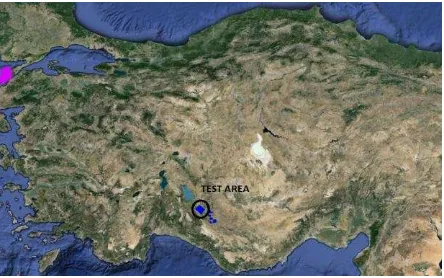
Test area is in Seydisehir which is the province of Konya (Turkey), including an area of 17.5 km in the south-east direction and 13.5 km in the north-west direction.
Fig. 1. The location of the test area
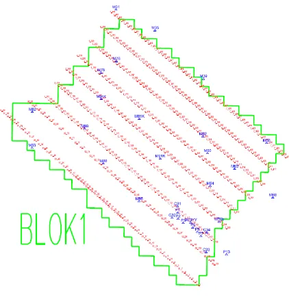
Intergraph) DMC (0173) digital aerial camera on August 15, 2014. Data for test area and flight details are summarized in Table 1. In addition, the flight number of the column in the test area, taken photos in each column, the number and location of the ground control points within blocks are illustrated in Figure 3.
Flights has been carried out with much care by GPS/IMU 30 full control points are established in order to control the accuracy of the photogrammetric triangulation and orthophoto products and their coordinates are determined in the ITRF system.
Number of column is 9 in the flight, two different height flight operations were performed comprising different heights due to the land 7 column + 2 column.Orthophoto maps in the test area named due to the 1/1000 Turkey National Index System coordinates are determined in WGS84 ellipsoid datum system in ITRF96 2005.0 epoch. Digital elevation model data for the production of orthophotos is produced with 2m, 5m, 10m automatic image correlation.
Fig.2 The Test area and the Flight columns
The production of Orthophoto and mosaic images are performed separately in pixel sizes according to 10, 30 and 50 cm GSD. Inphone Box 6.0 software was used for the orthophoto production.
Digital Camera Z/I - DMC01-0173
Focal Lenght 120 mm
Frame dimensions 13842 x 7680
Pixel Size 12 μm
Side and Forward %70 / %30
Number of columns 9
Number of Photographs 463
Approx. Photograph scale 1/13500 Average Ground height 1204 m Number of Ground Control
Points
30
Number of check points 5
IMU System FSAS
GPS System Novatel
Flight direction North West-South east
Table 1: Flight Parameters
Fig 3. The position of Ground Control Points in the Test Field
2.2 Photogrammetric Triangulation
The choice of tie points for photogrammetric triangulation measurements are performed automatically.
The ground control and characteristics points measurements are conducted by the operator. Thus, measurements spread over the entire photographic image and the increasing of the degree of freedom for the adjustment calculation is ensured.
Tie points are chosen so as to be visible from at least four images and measurements were made. For the image matching, 27 points are selected and measured near the Gruber points area. The point intervals for the automatic measurements done to produce Digital terrain model are selected as 2, 5, 10 m. Besides these points characteristical points on the terrain are measured manually.
For the measurement of the aerial triangulation points Inpho (ver.6) Digital photogrammetric software was used. Using this software the measured image coordinates are adjusted according to the bundle adjustment method with additional parameters. MATCH AT (vers.6) is used for the least squares adjustment. Before the least squares adjustment all the measurements are cleaned from blunders.
The following parameters are included in the adjustment calculation:
- Self-Calibration - GPS-Mode - Drift-Mode - GPS-Antenna - INS-Mode - INS-Limits
- Atmospheric refraction and earth curvature
For the ground control points X,Y = 0.03 m
Z = 0.05 m
For the automatic measured tie points l = 0. 002 mm
For the automatic measured tie and ground control points l = 0.002 mm
Direct georeferencing system GPS X,Y,Z = 0.10 m INS æ, φ ,ω = 0o.010
The results of the block adjustment is given in Table 2
The name of the parameter Computed value
number of observations 810223
number of unknowns 250667
redundancy 559556
sigma naught 1.9 micron
RMS automatic points in photo (x) 1.5 micron
RMS automatic points in photo (y) 1.7 micron
RMS control and manual points in photo (x) 2.4 micron
RMS control and manual points in photo (y) 2.2 micron
RMS control points (X) 0.028 meter
RMS control points (Y) 0.040 meter
RMS control points (Z) 0.035 meter
RMS IMU observations omega 0.0 deg
RMS IMU observations phi 0.0 deg
RMS IMU observations kappa 0.0 deg
RMS GNSS observations (X) 0.002 meter
RMS GNSS observations (Y) 0.002 meter
RMS GNSS observations (Z) 0.003 meter
mean standard deviations of rotations omega 0.5 [deg/1000]
mean standard deviations of rotations phi 0.6 [deg/1000]
mean standard deviations of rotations kappa 0.2 [deg/1000]
mean standard deviations of translations (X) 0.018 meter
mean standard deviations of translations (Y) 0.017 meter
mean standard deviations of translations (Z) 0.017 meter
Table 2. Block Adjustment RMS
The difference between the coordinates of the common points of the blocks which are adjusted indepently from one to other is smaller than 5cm at the position and 10 cm at height.
To test the accuracy of the block adjustment, some ground control points are used as check points. 5 from 30 control points are used as check points. The computed standard errors of these points are as follows:
(σX=0.031m, σY=0.033m, σZ=0.056m)
2.3 Orthophoto Production
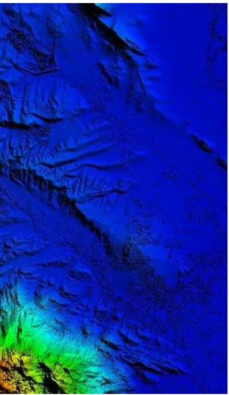
The data for the digital terrain model is collected automatically by the operator. For the orthophoto with 10cm GSD 2m, for 30 cm GSD 5m, and for 50 cm GSD 10m point interval has been choosen automatically and using these intervals corresponding height values are obtained from the stereomodel. Thereafter, the heights of the characteristic points of the ground are measured by the operator. The 3D solid model of the test field is shown in Fig.4.
The orthophoto image is designed block based. Therefore, these blocks which are consisting of many aerial photographs
were corrected for seamline and was processed for a radiometric enhancement. A region of the test field with 10 cm GSD orthophoto is shown in Fig.5
Fig. 4 The solid model of the test field
2.4 The Accuracy of the Orthophoto
Using manual and automatic photogrammetric triangulation measurements made and ground control points mentioned above the exterior orientation parameters (Xo, Yo, Zo, ω, φ,
К) of the photographs can be calculated in accuracy under the international technical accuracy criteria. The main task of ground control points is the solution of photogrammetric triangulation.
Furthermore, they can be used in the accuracy analysis of the DTMs. Many number of photogrammetric triangulation points has not to be a meaningful contribution to the mathematical model. Most of these points can be used as a checkpoint and gives information about the absolute accuracy of the adjustment calculation.
The accuracy of digital terrain models is obtained by checkpoints in the European Union countries.
In the guidelines the "Assessment of the Quality of Digital Terrain Models " published by Eurosdr the (European Spatial Data Research) position and height accuracy of the digital terrain model is determined by the following formula (Kapnias, D. 2008).
σxy= 0.75*GSD ; σz= 0.53*GSD
It is required that the σz σxy values calculated from the
difference between real ground coordinates and the checkpoint coordinates calculated from the digital terrain model is not exceed the value found from the formula above.
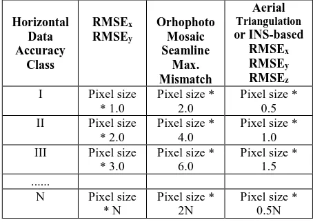
In the instruction the "Accuracy Standards for Digital Geospatial Data, March 2014) applied by ASPRS (American Society for Photogrammetry and Remote Sensing) position (x, y) and height (z) accuracy of the digital orthophoto images is classified according to method and accuracy values. (ASPRS,2014).
Very high accuracy seeking engineering measurement based services Class I, high-accuracy map producing works (large-scale map production) Class II, less accurate mapping producing works have been classified as Class III.
This horizontal accuracy standards for digital orthophotos prescribed by this grouping is shown in Table 3.
Horizontal
Table 3. Horizontal accuracy standards for orthophoto (ASPRS,2014)
By analysing Table 3, in order to produce orthophotos with 10cm accuracy in the content of Works Class I accuracy of the points obtained by photogrammetric triangulation adjustment must be smaller than 5cm, and the geodetic accuracy of the ground control points established for photogrammetric triangulation must be in 2.5cm or less. Digital orthophotos produced in this work provide these accuracy.
Data for digital terrain model in the test area as described above is obtained automatically by the operator.
For orthophotos with 10 cm GSD 2m, 30cm GSD 5m and 50cm GSD 10m intervals are used to obtain height value automatically from stereo models.
Then, the heights of characteristic points of the model (water collection and distribution lines, slope points, peaks, etc.) were collected manually by the operator. In this way, three separate digital elevation model was obtained.
Coordinates of 30 ground control points established on the ground before photographic Works and the with geodetic method determined coordinates of selected 439 points on the ground are compared with their coordinates obtained from three separate digital elevation models to obtain information about the accuracy of orthophotos.
The results are given in Table 4.
The accuracy of control points established for the photogrammetric triangulation can be seen from Table 2; as
(σX = 0.028, σY = 0.040m, σZ = 0.035m). The number of these points are 30.
Accuracies of the on the topographic surface selected and their coordinates with geodetic methods determined 439
points are as follows: (σX = 0.062m, σY = 0.059m,
Table 4. Accuracy of the DTM
GSD = 10cm (1: 1000 scale mapping), GSD = 30cm (1: 5000 scale mapping) and GSD = 50cm (1: 10,000 scale mapping) All of these accuracy values provide the ASPRS Standard.
3. RESULTS
There is an increased demand in recent years for the Orthophoto products. The most important factor by this demand is the height accuracy.
The most important factors that determine the height accuracy are the accuracy, number and distribution of ground control points in the block in the terrain elevation accuracy, the distribution in number and block, can be listed as the specifications of the digital aerial camera used.
The accuracy, number and distribution of ground control points, the specifications of the digital aerial camera used can be listed as the most important factors that determine the height accuracy.
Flights are done according to the selected GSD which is evaluated due to the orthophoto mapscale. The expected position and height accuracy are different for each map scale.
On the other hand in case of inability of the new flight if the existing aerial photos are used, orthophotos may be produced again in the pixel values corresponding to required GSD.
As can be seen from the results of this study (Table 5) if the parameters like accuracy of photogrammetric ground control points, the number, distribution within the block, GNSS / IMU sustained flight operations, the accuracy of the adjustment of photogrammetric triangulation, the stereo observations provide international standards than the accuracies of orthophotos produced with different pixel sizes provided the international standarts.
These results may provide economical solution and time savings to the map producers.
ACKNOWLEDGEMENTS
The Presantation is Supported by Selcuk University Scientific Research Projects Coordination Unit and Istanbul Technical University Scientific Research Projects Coordination Unit.
REFERENCES
Graham, R., Koh, A., 2002. Digital Aerial Survey, Theory and Practice, Whittles Publishing Caithness, ISBN 1-870325.
Kapnias, D., Milenov, P., Kay, S., 2008. Guidelines for Best Practice and Quality Checking of Ortho Imagery, JRC European Commission, Issue 3.0.
Hoffmann, R., Reulke R., 2008. Aspects of the Standardization of Sensor and Data Fusion Remote Sensing Data, The International Archives of the Photogrammetry, Remote Sensing and Spatial Information Sciences, Vol. XXXVII, Part B1.
Jacobsen, K., 2008. Satellite Image Orientation, The International Archivesof of the Photogrammetry Remote Sensing and Spatial Information Sciences, Vol.XXXVII, Part B1.
Joachim, H., DEM, 2009. Jeneration Using a Digital Large Format Frame Camera, Photogrammetric Engineering & Remote Sensing, Vol:75, No:1.
Oskanen, J., 2011. Digital Elevation Model Error in Terrain Analysis, Publication of the Finnish Geodetic Institute.
EuroSDR, 2011. (European Saptial Data Research), Official Publication No:60, Assessment of the Quality of Digital
Terrain Models, by Höhle, J., Potuckova, M.
ASPRS, 2014. (American Society for Photogrammetry and Remote Sensing), Accuracy Standarts for Digital Geospatial Data.