a
The Langmuir Laboratory for Atmospheric Research, Socorro, NM, USA b
Space and Atmospheric Sciences Group, Los Alamos National Laboratory, Los Alamos, NM, USA c
National SeÕere Storms Laboratory, Norman, OK, USA d
Department of Physics and Astronomy, UniÕersity of Mississippi, MS, USA
Abstract
We have designed a new instrument to measure the current flowing along balloon rigging line during flights through thunderstorms. This instrument was tested in a high voltage facility and used to collect line current data during one balloon flight into a thunderstorm. Using these data, worst-case calculations are made; as such, we claim that they are the upper limits of any alteration
Žto the measured electric field or particle charge that may occur, and the real number is likely.
much less. It is postulated the rigging-line current could have two separate effects on the measured
Ž . Ž .
electric field: 1 reduction of the field due to emission of corona ions, and 2 enhancement of the
Ž
field due to the insertion of a long thin ‘conductor.’ Even with current as high as 1mA the largest
.
measured was around 50–100 nA , these two effects were found to be abouty1% andq1%, respectively. Also, the calculated worst-case alteration to charged precipitation measurements is about 0.1 pC. Thus, with proper efforts to make the rigging line as poor a conductor as possible, it seems that we are justified in stating that these effects are negligible.q1999 Elsevier Science B.V. All rights reserved.
Keywords: Electrical current; Balloon; Rigging line; Thunderstorm
1. Introduction
For nearly a century now, scientists have been making atmospheric electricity measurements with instrumented balloons. Most of these measurements had the
follow-)Corresponding author. NASArMSFCrUSRA, 977 Explorer Blvd., Huntsville, AL 35806, USA. Tel.: q1-256-922-5804; fax:q1-256-922-5723; e-mail: [email protected]
0169-8095r99r$ - see front matterq1999 Elsevier Science B.V. All rights reserved. Ž .
ing things in common: an envelope filled with some light gas that lifts a measuring device upwards through the atmosphere. Necessarily, the measuring equipment is connected to the envelope with some type of rigging line. Our research focuses on measuring the electrical properties inside thunderstorms, an extremely hostile environ-ment to instruenviron-mentation for many reasons. This paper is concerned with two of those reasons: high electric fields and moderate to high liquid water contents. It turns out that under these conditions, nylon monofilament rigging line can carry an electrical current.
Ž .
Jonsson 1990 took pieces of nylon monofilament rigging line, wetted them, and connected them to a power supply, forcing an electrical current to flow in the line. Jonsson suggested that the same thing might be occurring during balloon flights and wondered what effect this leakage current might have on the electrical measurements. Note that the rigging line measurements presented by Jonsson were made in a labora-tory, using a method that was very different from what happens to our balloon train inside a thunderstorm. Nevertheless, we were compelled to find out what, if any, relationship these laboratory measurements had with what happens to rigging line during a balloon flight. An instrument has now been designed, tested in a high voltage facility, and used to measure real rigging-line current during one balloon flight into a thunder-storm.
2. Instrumentation
For the past two decades, our primary rigging line has been nylon monofilament, 1.5–2.0 mm in diameter. Beginning in 1990, we have treated our monofilament lines with water repellant coatings—a mixture of DuPont’s Nalanw
W and Zepelw
. Jonsson
Ž1990 reported that the coated monofilament exhibited an order of magnitude reduction.
in leakage current when compared with uncoated line. He also tested another type of line we had used occasionally, which is made from small nylon fibers that are braided and coated with wax—also referred to as lacing cord. He found that this line exhibited an order of magnitude less current than coated monofilament. Based on these results, we altered our balloon rigging in the following way: within 1 m of the electric field meter or particle charge sensor, waxed nylon line is used; farther away, where extra strength is required, the coated nylon monofilament line is used.
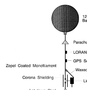
The balloon train in Fig. 1 shows the four instruments used. Nearest the balloon are two Vaisala radiosondes: one is an RS80-15L that uses LORAN for tracking and the other is an RS80-15G that uses GPS. These sondes were tracked by an M-CLASS
Ž .
system Rust et al., 1990 and a Vaisala Digi-CORA-II MW15 groundstation, respec-tively. Next is the line current sensor, described below. At the bottom is the electric field
Ž .
meter EFM , which measures the strength of the electric field. Details of the electric
Ž . Ž .
field meter can be found in Winn et al. 1978 and Marshall et al. 1995 .
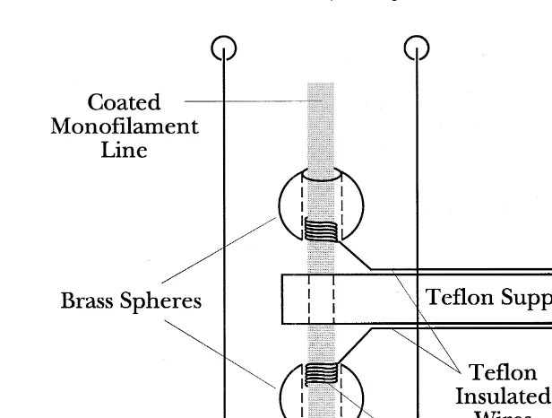
The physical package and line attachment of the line current sensor are shown in Fig. 2. The current flowing in coated monofilament line is measured by wrapping wires
Ž
around the line in two places, separated by a dry section of line where it passes through
w .
Fig. 1. The instrument train used to collect the line current data. Near the top of the train are the radiosondes: a LORAN tracking sonde and a GPS sonde, both of which provide atmospheric pressure, temperature, humidity, horizontal winds, and three-dimensional position. About 3 m from the tail of the balloon is the line current instrument, which measures currents flowing along the rigging line. At the bottom is the electric field meter
ŽEFM , from which the components of the electric vector can be determined. The let-down reel contains about.
10 m of line.
instrument provides a low-impedance path for current, creating a current divider where nearly all of the line current flows through the instrument. To help increase the corona threshold of the sharp, bare wire ends that attach to the nylon line, two things were done.
Ž .
First, brass spheres 12.7 mm diameter are used to cover the bare end of the wire where it wraps around the line. These spheres are held in place by a bit of RTV silicone sealer around the bottom of each sphere. Second, the attachment section of line is surrounded
Ž .
with a shielding cylinder aluminum, 7 cm diameter, 33 cm tall . This cylinder is centered on the line with Teflon spacers and the sharp upper and lower ends are covered with Tygonw
Fig. 2. Diagram of the line current sensor and its attachment to the coated monofilament line.
that it was measuring its own corona current. The shielding cylinder solved this problem, and as flown, the instrument did not measure current in dry line up to an
Fig. 3. Schematic of the measuring circuit. The input from the rigging line is passed through a 400-MHz filter to remove noise from the telemetry transmitter. The integrator is constructed by connecting a capacitor in the
Ž .
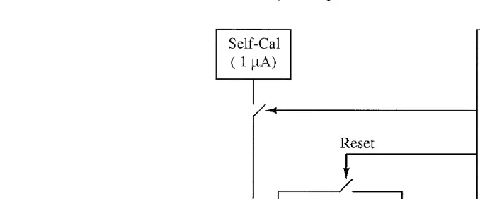
Ž .
Fig. 4. System diagram of the line current sensor. The self-calibration unit Self-Cal provides a known current for calibration. The low pass filter helps to remove lightning transients. The microcontroller controls the
Ž .
analog-to-digital converter ArD and reads its output data. These data are formatted and sent to the transmitter. The microcontroller also resets the integrator when necessary.
Ž .
electric field strength of 125 kVrm the largest field strength tested . The shielding cylinder is open at the top and bottom so that the line will be subjected to the cloud environment.
Ž . Ž
The measuring circuit is a simple operational amplifier op-amp integrator see Fig.
.
3 . To help remove noise caused by the telemetry transmitter, a 400-MHz filter is used at the inputs of the integrator. We are interested in measuring steady current flow, not lightning transients or corona bursts, so the output of the integrator was low-pass filtered. The op-amp used is an Advanced Linear Device’s ALD1701, chosen for two
Ž . Ž .
reasons: 1 low bias current 1 pA , which is important so that the op-amp does not
Ž .
significantly charge the capacitor by itself, and 2 it can provide output voltages nearly equal to its power supply voltages, resulting in maximum dynamic range. The output of the integrator is sampled by a 12-bit ArD converter at 20 Hz. The digital data stream is telemetered to ground and stored there. When the output of the integrator gets close to either the positive or negative limit, the microcontroller closes a switch that shorts out the integrating capacitor, resetting the integrator. The integrator uses a 0.1mF capacitor;
Ž .
the ‘on’ resistance of the switch DG304 is about 30 V. To be sure that the capacitor is fully discharged, the switch has to stay closed for five RC time constants or not less than 15ms. There is also a built-in 1-mA current source that the microcontroller turns on for a few hundred milliseconds at power-up and again during the flight if a few hundred consecutive samples are nearly the same. The system diagram is shown in Fig. 4.
3. Observations
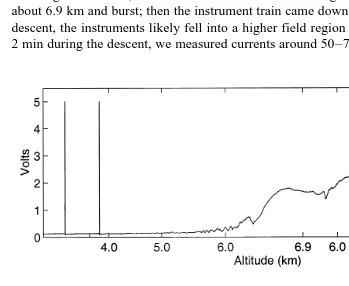
We flew the line current sensor into a thunderstorm over Langmuir Laboratory, in the Magdalena Mountains of central New Mexico. The balloon was released at 1940 UTC
Ž .
Fig. 5. The electric field, temperature, dewpoint temperature, and line current are shown in Fig. 6.
From about 4 km to about 5.7 km, the line current was 0.02 nA, while the electric field initially was less than 10 kVrm, climbed to 17 kVrm and then dropped back to 5 kVrm. Then, at about 5.7 km altitude, we measured current of 0.12 nA, where the field exceeded 10 kVrm for the second time. At 6.2 km the current increased to 0.85 nA when the field had risen to about 25 kVrm. Above 6.3 km, telemetry from the field
Ž .
meter was too weak to receive because of a hardware problem at the ground , ending the electric field data for this flight. The current then briefly went toy2.1 nA, then rose to as high asq2 nA, then decreased to near zero. During this time, the balloon rose to about 6.9 km and burst; then the instrument train came down on its parachute. During its descent, the instruments likely fell into a higher field region of storm, because for about 2 min during the descent, we measured currents around 50–70 nA. Since the line current
Fig. 5. Shown here is a time series of integrated current; the slope of this trace is the line current. The
Ž .
horizontal axis has been translated to altitude. The upper trace shows the entire flight about 1500 s , with balloon burst occurring at 6.9 km. The two spikes that occurred prior to 4.0 km were self-calibration pulses of
Ž .
Ž .
Fig. 6. Profile of electric field and thermodynamic data from the LORAN sonde . On the left, electric field
Ž .E in kVrm, temperature T and dewpoint temperature TŽ . Ž .d in degrees Centigrade; on the right, line current in nanoamperes. The line current sensor integrates current, so the current shown is the slope of the output trace in Fig. 5.
data were very noisy at this time, it is difficult to determine the current exactly; it may have been as low as 20 nA or as high as 100 nA.
4. Discussion
Ž .
Although Jonsson 1990 measured current in nylon monofilament lines, his experi-mental setup was quite different from balloon rigging lines as flown. He set up a power supply and connected various types of continuously wetted lines across the power
Ž
supply terminals. He found that with a potential gradient of 2 kVrm 500 V applied
.
across a 0.25-m-long piece of rigging line , he could get currents to flow in wetted,
Ž .
Zepel-treated monofilament of up to 1 nA. With a field of 10 kVrm five times as large
Ž .
we measured a current of 0.02 nA fifty times smaller . During a balloon flight, the rigging line is an isolated piece of ‘conductor’ through which no current flows unless a ‘circuit’ is made. This happens only when the upper and lower parts of the instrument train emit corona ions. We speculate that this is why our measurements are so different
Ž .
—Jonsson 1990 attached his lines to his power supply with wires; our line is connected to the thuderstorm’s ‘power supply’ via corona. The impedance at these corona sources is in series with the rigging line, and helps to reduce the total current. Using the new instrument described herein, we measured rigging-line currents inside a thunderstorm that ranged from 0.02 nA up to possibly as high as 100 nA. Admittedly, this one balloon flight was not optimal, due to the failure of the field meter telemetry.
Ž . Ž .
But it was enough to show: 1 that the line-current instrument works, 2 that currents
Ž .
expect. Now the question remains: is this current significant? Or, how much current must flow in the rigging line to have an effect on our E and particle-charge measure-ments?
There are two effects that the rigging line might have on the ambient electric field at
Ž .
the location of the EFM. First is the emission of corona ions of opposite charge from the ends of the line. This effect will serve to reduce the field at the EFM. Second, since the line is somewhat conductive, and since the EFM is directly below the end of this long thin conductor, it will cause an enhancement of the field at the EFM. These two effects will be treated separately.
4.1. Emission of corona ions
A reasonable place for corona ions to be emitted is at the swivel, about 1 m above the
Ž .
EFM recall Fig. 1 . For the following calculations we will use a geometry that is a vertical line, 9 m in length starting 1 m above the EFM; the coordinate system is shown in Fig. 7. Assume that the field is pointed vertically upwards or Es qE ; this meansz that positive ions will be emitted from the top of the line and negative ions from the bottom. Next, we make some simplifying assumptions which will be accounted for later. Each assumption will make the field alteration worse than reality, so the calculation will give a ‘worst-case’ value. First, we assume that the corona ions emitted off the ends of the rigging line will stay in a line, forming a line of charge. Second, we assume that the current has been flowing at a steady value ‘long enough’ that the line charge will be
Ž .
instantly attach to hydrometeors. The real answer will be somewhere between these two extremes and will depend on the types and number densities of particles present.
The negative charge will be a line of charge extending from 1 m above the EFM to negative infinity. The 1 m of line charge above the EFM and the 1 m of charge below the EFM cancel by symmetry, leaving the charge from 1 m below the EFM to negative infinity. Written as an integral,
driven by the electric field. This was was measured by Varney 1953 ; for our range of
Ž . y4
E and p atmospheric pressure , the ion speed isÕs2=10 mrs per Vrm. So for a
field strength of 10 kVrm, Õs2 mrs; for 100 kVrm, Õs20 mrs, relative to the
balloon. From our measurements we found a steady current of about 0.2 nA in a field of 10 kVrm. These values give ls y0.1 nCrm. The strongest fields we typically measure in thunderstorms is on the order of 100 kVrm. Note that if both measured values are increased by an order of magnitude, i.e., to 2 nA and 100 kVrm, ldoes not
Ž .
change. So, for this amount of negative line charge density below the EFM, Eq. 1 givesy4.5 Vrm.
Similarly, the second part can be calculated as follows
q1 0
Now assume a worst case: we measured currents up to about 70 nA; what if the current flowing in the line was much bigger than that, say 1 mA? This would also require the assumption of a very large field value. In a very few cases, the balloon-borne EFM has measured a peak field as large as 150 kVrm. This field strength would result in an ion speed of 30 mrs, and a line charge density of lf33 nCrm. Using this value
Ž . Ž .
Up to now, we have assumed that the corona ions remain unattached, free ions for the duration of their field contribution. Now, we take the opposite stance and assume that they immediately attach to cloud particles and immobilize. In this case, the negative charge still extends from the bottom of the line to negative infinity, but the positive charge now extends from the top of the line to negative infinity. So the negative charge is completely cancelled, and the only positive charge left uncancelled is along the rigging line—from 1 m above the EFM to 10 m above. This integral is
q1
l d z l y1 y9l
q1
Es
H
4pe z2 s4pe z s40peŽ .
3q10 o o q10 o
This time, the field meter is moving towards the line charge at the rise rate of the
Ž .
balloon, about 5 mrs. For a large current of 1mA and field of 150 kVrm , this gives
Ž .
us a line charge density of 200 nCrm. Evaluating Eq. 3 we get a contribution ofy1.6 kVrm or about 1% of 150 kVrm.
Lastly, we account for our simplifying assumptions. We assumed that the charge coming from the ends of the rigging line remains in a line; actually, the charge spreads apart due to mutual repulsion and forms a plume which is conical for a distance, then straight along the field lines as a cylinder. This means that the charge will spread out, placing it farther from the EFM, reducing its field contribution. Another way of thinking of this: originally, we invoked symmetry to cancel the line charge 1 m above and 1 m below the EFM, but because the charge is not in a line, symmetry is broken; in the meter above the EFM the charge is more intense than stated, so it will cancel more than 1 m of
Ž .
charge below the EFM. This means the upper limit of integration in Eq. 1 might really
Ž .
bey2, reducing the field contribution from Eq. 1 by a factor of 2. We also assumed that the currents flow for a ‘long’ time, say 10 s, at a steady value. The data show that for most of the flight the current was steady or slowly varying.
4.2. Field enhancement due to the rigging line
Like most real world electrostatics problems, this problem has difficult geometry and imperfect materials. We will approximate the line as a long, thin ellipsoid-shaped
Ž .
conductor. Smythe 1950 has solved the problem of the field outside a conductor
Ž .
shaped as an ellipsoid. Moore 1983 applied that calculation to the problem of lightning rods. The following calculation benefits from both of these examples.
Smythe worked this problem in a mixture of cartesian and confocal ellipsoidal coordinates. The confocal ellipsoidal coordinates,hand j, represent a family of ellipses and hyperbolas, respectively. Since we are interested in the field directly above or below the tip, our point of interest falls on a line of constant js1.
and the field enhancement is given by
These chosen values give a field enhancement of about 25% at a distance of 1 m from the tip. If we assume that our wetted monofilament line is at least two orders of magnitude less effective in field enhancement than a perfect conductor, then the
Ž .
enhancement is 1% or less. Since Jonsson 1990 measured the resistivity of wetted, Zepel-coated monofilament line and found it ranged from 109 to 1012 Vrm, this seems like a safe assumption.
4.3. Effect of the rigging line on particle charge measurements
Ž .
Jonsson 1990 also claimed that the current flowing along rigging lines might be affecting charged particle measurements. For this calculation, consider 1-mm diameter precipitation particles and 10-mm diameter cloud particles. It is very unlikely that a precipitation particle will collect an emitted corona ion, since in a given volume there
Ž .
are so many more cloud particles Pruppacher and Klett, 1978 . So we will assume that the corona ions emitted by the line are captured by cloud particles. The q–d sensor
ŽBateman et al., 1994 , which measures the charge of particles falling through it, is.
configured so that it is about 2 m horizontally from the nylon monofilament line. We will assume that the emitted corona ions evenly distribute in a 2-m radius circle, or an area of As12.6 m2, before attaching to cloud particles.
This calculation is similar to the one above where ions attached immediately to cloud particles. For reasons mentioned above, the only place where the emitted charge has not yet been canceled is along the line, or a length of about 10 m. A balloon rise rate of
rsIrÕAf16 nCrm3. A 1-mm raindrop falling through this 10-m-long cylinder will
sweep out a volume of 7.85=10y6 m3. If it collects every cloud particle in that volume
Žworst-case assumption , it will gain a charge q. srVs0.12 pC. Note that the detection limit of the present q–d instrument is about 1–2 pC.
< <
This calculation is a worst case. Note that typical values for rtotal in small, isolated
3 Ž .
thunderstorms are 0.1–2.0 nCrm Marshall and Rust, 1991; Marshall et al., 1995 .
Ž .
Also, the emitted ions likely travel more than 2 m horizontally Brown et al., 1971 before they attach to cloud particles, putting them beyond the q–d sensor.
Ž .
Another problem that Jonsson 1990 mentioned was the emission of charged
Ž .
hydrometeors from the line. As we have mentioned previously Bateman et al., 1994 , the chance of ejecting a droplet at the exact azimuth and elevation angle to make a clean pass through the q–d sensor seems extremely remote, especially considering the balloon’s 5 mrs upward velocity relative to the air.
5. Concluding remarks
We have measured current flowing along balloon rigging lines inside a thunderstorm. Extrapolating from these data, we have calculated upper limits for reduction in E due to the emission of corona ions from the ends of the nylon monofilament rigging line. The reductions range from 0.22% to 1%. Also calculated was the enhancement of E due to measuring the field 1 m off the end of and directly in line with a long, thin, ellipsoidal conductor—around 25%. At worst, wetted Zepel-treated nylon monofilament line might result in an enhancement of 1%. Both ion emission and field enhancement are very small effects. We have also calculated the effect that corona from the rigging line might have on charged particle measurements. At worst, it might alter the charge on a particle by 0.1 pC, but is likely much less than this.
Ž .
Jonsson and Vonnegut Jonsson, 1990; Jonsson and Vonnegut, 1995 argue that current flowing in the rigging line might be significantly altering our electrical measure-ments. The measurements and calculations reported herein show that we are justified in stating that these effects are negligible, even with currents of up to 1mA flowing in the rigging line. These measurements and calculations also support the conclusions of
Ž .
Marshall and Marsh 1995 that current flow in balloon rigging lines have a negligible effect on electric field and precipitation particle charge measurements inside thunder-storms.
Acknowledgements
balloon-borne instrumentation. J. Geophys. Res. 95, 22539–22545.
Jonsson, H.H., Vonnegut, B., 1995. Comment on ‘Negatively charged precipitation in a New Mexico thunderstorm’ by Thomas C. Marshall and Stephen J. Marsh and ‘Charged precipitation measurements before the first lightning flash in a thunderstorm’ by Stephen J. Marsh and Thomas C. Marshall. J. Geophys. Res., 16867–16868.
Marshall, T.C., Marsh, S.J., 1995. Reply. J. Geophys. Res. 100, 16869–16871.
Marshall, T.C., Rust, W.D., 1991. Electric field soundings through thunderstorms. J. Geophys. Res. 96, 22297–22306.
Marshall, T.C., Rison, W.R., Rust, W.D., Stolzenburg, M., Willett, J.C., Winn, W.P., 1995. Rocket and balloon observations of electric field in two thunderstorms. J. Geophys. Res. 100, 20815–20828. Moore, C.B., 1983. Improved configurations of lightning rods and air terminals. J. Franklin Inst. 315, 61–85. Pruppacher, H.R., Klett, J.D., 1978. Microphysics of Clouds and Precipitation. Reidel, Dordrecht, Holland, pp.
9–55.
Rust, W.D., Davies-Jones, R., Burgess, D.W., Maddox, R.A., Showell, L.C., Marshall, T.C., Lauritsen, D.K.,
Ž .
1990. Testing a mobile version of a cross-chain LORAN atmospheric sounding system M-CLASS . Bull. Am. Meteorol. Soc. 71, 173–180.
Smythe, W.R., 1950. Static and Dynamic Electricity. McGraw-Hill, New York, pp. 168–169.
Varney, R.N., 1953. Drift velocity of ions in oxygen, nitrogen and carbon monoxide. Phys. Rev. 89, 708–711. Winn, W.P., Moore, C.B., Holmes, C.R., Byerley, L.G., 1978. Thunderstorm on July 16, 1975, over Langmuir