Behavior of Reinforced Concrete Frames In-Filled with
Lightweight Materials Under Seismic Loads
Imran, I.1, Aryanto, A.2
Abstract: This paper presents an experimental and analytical research conducted to study the in-plane behavior of reinforced concrete (R/C) frames in-filled with lightweight materials. The tests were performed on two single bay, single story in-filled frame specimens with ½ scale models. One of the test specimens was in-filled with lightweight materials, i.e. autoclaved aerated concrete (AAC) blocks, and the other, used as the comparison, was in-filled with clay brick materials. The loading used in the tests was in the form of cyclic in-plane lateral loads, simulating earthquake forces. Behavior of the frame structures was evaluated through the observed strength and deformation characteristics, the measured hysteretic energy dissipation capacity and the measured ductility. The experimental results show that the R/C frame in-filled with AAC blocks exhibited better performance under in-plane lateral loads than that in-filled with conventional clay bricks. In the analytical work, the performance of some analytical models available in the literature was evaluated in simulating the experimental results
Keywords: lightweight materials, in-filled frames, autoclaved aerated concrete, ductility, hysteretic behavior.
Introduction
The behavior of in-filled reinforced concrete (R/C) frames has been studied experimentally and computationally by a number of researchers [1, 2, 3, 4, 5]. It has been recognized that infill materials give significant effect to the performance of the resulting in-filled frame structures [6]. Most of the researches carried out in this area focused on parameters such as the variation of geometry, the strength of infill materials and the relative stiffness of infill to frame elements. The study of the effect of types of infill materials used (lightweight versus normal weight masonry) on the behavior of in-filled R/C frames is however still limited. Autoclaved aerated concrete (AAC) is one of the lightweight materials frequently used as infill materials and has been introduced into Indonesian construction market a decade ago. The material weight of ACC is approximately one third of normal weight clay unit. It has been established that the less the weight of infill materials used, the less the earthquake forces generated in the structures. Nevertheless, lightweight materials usually have less strength and less stiffness than the normal weight materials.
1 Structural Engineering Research Group, Faculty of Civil and Environmental Engineering, ITB, Bandung, Indonesia.
Email: [email protected].
2 Former Graduate Student, Civil Engineering Department, Faculty of Civil and Environmental Engineering, ITB, Bandung, Indonesia. Note: Discussion is expected before November, 1st 2009, and will be published in the “Civil Engineering Dimension” volume 12, number 1, March 2010.
Received 12 March 2009; revised 25 March 2009; accepted 3 April 2009.
the measured ductility. In the analytical work, some analytical models available in the literature were used to estimate the strength and stiffness of the test specimens. The experimental program and the results of the study are outlined in the following sections.
Experimental Program
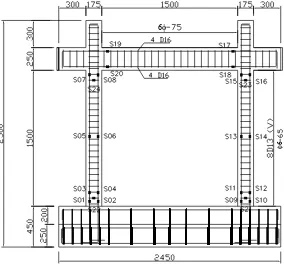
The experimental work presented in this paper was focused on the performance and behavior of R/C frames in-filled with lightweight materials, i.e. AAC blocks, under in-plane lateral loads, simulating earthquake forces. As a comparison, the behavior of a R/C frame, in-filled with normal weight clay unit commonly used in the building constructions in Indonesia, was also investigated in this study. The test model configurations are shown in Figure 1.
The selected prototype of in-filled R/C frame was designed to meet the requirement of intermediate moment frame in accordance with the Indonesian Concrete Code Sect. 23 [9], which is basically equivalent to ACI 318-08 Sect. 21 [10]. Due to the limitation of available research facilities, a scaling factor of one half was adopted to obtain a test model. The test model is single story and single bay system. Each model has typical height of 1750 mm and typical width of 1675 mm between columns centerlines. The R/C frame structure consists of 175x175 mm square columns and 150x250 mm beams. All infill materials used in the frame have the same slenderness ratio h/t (height/thickness) of 15 and an aspect ratio h/l (height/bay length) of 1.0.
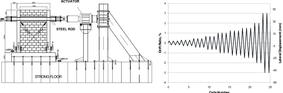
The test models shown in Figure 1 were constructed on stiff R/C beam and bolted to the laboratory strong floor. To eliminate out of plane movement, the specimens were laterally braced by steel frame. The cyclic lateral load was applied by servo-controlled hydraulic actuator having a load capacity of 1000 kN and a maximum stroke of + 100 mm. To avoid any tensile force applied to the loading beam during the
application of load reversals, four stiff steel rods were used (Figures 2). Linear variable displacement transducers (LVDTs) were placed in several locations in the specimens to measure displacement at different locations (Figure 2). Shear distortion in the specimen during the test was measured using 2 LVDTs placed diagonally (Figure 3). A total of twenty-four strain gauges were installed on some reinforcing steel bars in each specimen (Figure 4), to measure strain values needed for calculation of moment, shear and axial forces in the frame members. All the instrumentations were monitored throughout the tests using Data Acquisition System.
Figure 1. Infilled R/C Frame Specimens
In this experimental work, lateral loads were applied to the loading beam at the top of wall using displacement control with the history shown in Figure 2. The loading history used is adopted from the ACI recommendation for cyclic load testing of R/C structural elements [11]. Displacement levels corresponding to drift of 0.1% up to 3% were subsequently applied.
In addition to structural tests, a set of material tests were performed in this study. These include compression tests of masonry units, compression tests of mortar specimens, compression tests of
course masonry prisms and bond/shear tests of masonry prisms. Material tests were also conducted on reinforcing bars and concrete samples. The results of material tests are summarized in Table 1. It can be seen from Table 1 that the actual concrete strengths of the test specimens were 27.09 and 26.08 MPa, consecutively for test model 1 and model 2. Actual yield strength of longitudinal and lateral reinforcing bars in the columns was 488 and 280 MPa, respectively. The respective ultimate strength of the rebars was recorded at 625 and 387 MPa. In addition, the strength of AAC unit (2.9 MPa) was found to be lower than that of the clay unit, which was 4.57 MPa (Table 1).
LVDT
Figure 3. View of Test Setup
Table 1. Average Material Properties
Properties Test Model 1 Test Model 2 ASTM test or Source
Concrete fc’ 28 days = 27.09 MPa fc’ 28 days = 26.08 MPa C39/C39M-04 Mortar fcm’ 28 days = 11.22 MPa fcm’ 28 days = 10.45 MPa C109/C109M-99 Masonry unit FAAC = 2.90 MPa
Weight Density: 596 kg/m3
FClay = 4.57 MPa Weight Density: 1477 kg/m3
C 67-94 and C 140-96
Masonry prism fm’ 28 days = 2.97 MPa fm’ 28 days = 3.71 MPa C 1314-95 Reinforcing bars D16 : fy = 311.80 MPa , fu = 469.87 Mpa
D13 : fy = 488.42 MPa , fu = 625.61 MPa 6 : fy = 279.36 MPa , fu = 387.28 MPa
A 370-97
φ6
6φ
φ
φ
Column Reinf.
Beam Reinf.
Beam Reinf Column Reinf.Furthermore, there were two distinct types of mortar used in this infill masonry study. For test model 1, the 3 mm of thin bed mortar (i.e. PM (Prime Mortar)-100) was used to connect each AAC unit. This type of mortar is commonly suggested to be used in AAC construction. For test model 2, with a clay unit as infill material, general purpose mortar with cement to sand ratio of 1:4 (by volume) was used. This cement-sand ratio is commonly adopted in building constructions in Indonesia. The thickness of the connecting mortar for this case was 10 mm.
Results and Discussions
Crack Pattern
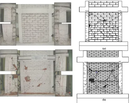
The final crack patterns of both test models are shown in Figure 5. In the AAC in-filled frame (test model 1), cracks began to form in the infill, along the diagonal of the infill wall. This crack formation occurred at 15.63 kN lateral load (or 1.34 mm lateral displacement). After that, at larger load, another diagonal crack parallel to the first one was observed. In the reverse loading, a diagonal crack
dominantly observed in AAC in-filled frame. At 27.16 kN lateral load (or 2.16 mm displacement), initial flexural crack started to develop in the columns. Then, initial shear crack appeared at 72.83 kN load (or 4.28mm displacement). In higher level of load, separation between infill and the frame along the column face was detected and continued to widen with the increasing load. After that, the infill material started to exhibit crushing failure. The major crushing failures were noted at the top right corner and middle height of infill wall, as shown in Figure 5a.
For clay infill specimen (test model 2), the first crack was found at lateral load of 26 kN (or lateral displacement of 1.25 mm). The cracks propagated diagonally across the mortar joint and also horizontally along the bed joint to form sliding shear. The major horizontal cracks occurred at approximately 1/3 and 2/3 of infill height. These horizontal cracks prevented the formation of diagonal X-cracks at the top half of the infill wall as shown in Figure 5b.
(a)
(b)
crack was observed at the bottom and top of the columns at 64.6 kN load (or 6.72 mm displacement). The shear crack at top of the columns continued to enlarge and the crushing of infill occurred at the locations where the horizontal cracks along bed joint met with the major diagonal cracks, as shown in Figure 5b.
Test model 2 exhibited a mode of failure that could be described as a frictional or sliding shear. The low shear strength of infill bed joint in this test model prevents the formation of diagonal cracks. In contrast, the AAC specimen (test model 1) exhibited strut formation, where the cracks propagated diagonally from the upper column to the base. This type of failure indicates that the thin bed mortar in AAC specimen had good bond characteristics.
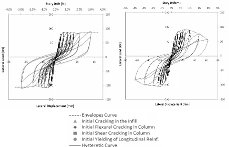
Hysteretic Behavior
The hysteretic curves for each test model are presented in Figure 6. Based on the load-deflection characteristics, both models exhibited basically similar peak loads. Nevertheless, test model 1 produced better hysteretic behavior than test model 2. More accelerated deterioration for similar intensity of lateral displacement was observed in test results of model 2 than that observed in test results of model 1. In addition, significant strength drop was clearly observed in the hysteretic curve of test model 2, started to occur at displacement larger than 20 mm (or at drift level greater than 1%). On the contrary, test model 1 showed only slight strength drop.
Figure 6. Hysteretic Load-Displacement Curves (a) Test Model 1–AAC infill (b) Test Model 2–Clay infill
Table 2. Summary of Experimental Results
Model
Frame cracking
load (kN)
Displacement at frame cracking load
(mm)
Infill cracking
load (kN)
Displacement at infill cracking load
(mm)
Maximum lateral load
(kN)
Displacement at maximum
Lateral load (mm)
Initial stiffness (kN/mm)
Failure mechanism
1 27.162 2.16 15.634 1.34 110.948 48.010 22.65
Strut or diagonal cracking
2 42.657 3.23 26.063 1.25 105.903 20.130 37.76
Lateral Strength
The test results (in terms of loads, displacements, stiffness, and failure mechanisms) are summarized in Table 2. It can be seen in that table that test model 1 exhibited higher maximum lateral load than test model 2. As the bare frame has an estimated lateral capacity of 41.6 kN, then the presence of AAC infill or clay infill basically increased the lateral capacity of the test specimen to more than 100%.
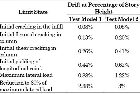
The drift levels (i.e story drift to story height ratio) corresponding to the damage in the specimens are summarized in Table 3. These can be used as design guidelines to estimate structural and non-structural damage/response of in-filled R/C frame buildings under lateral load. As can be observed from Table 3, in both test models, the initial crack of infill occurred at a drift of 0.08%, which can be stated as serviceability limit of this type of in-filled frame. The drift level at ultimate is defined as the drift at which the lateral resistance of the test model is reduced to 80% of its maximum lateral force. This ultimate level occurred at the second cycle of the drift 2.88% and 3%, respectively for test model 1 and 2. The drift level at which a major crack develoved in the columns ranges from 0,13% to 3%. In general, both test models exhibited good behavior under lateral load. Furthermore, the test models can still survive the drift level of at least 3% or more.
To predict the infill strength, several researchers proposed methods and formulations based on various theories. Mainstone [4] proposed empirical equation using elastic analysis by substituting the infill by equivalent diagonal strut in term of infill/frame stiffness parameter, λh. The lateral strength is computed as
H = 2.αc.hf’m cos2θ (1)
Table 3. Drift Levels at Various Limit States
Drift at Percentage of Story Height
Limit State
Test Model 1 Test Model 2
Initial cracking in the infill 0.08% 0.08% Initial flexural cracking in
column 0.13% 0.20%
Initial shear cracking in
column 0.26% 0.41%
Initial yielding of
longitudinal reinf. 0.44% 0.62%
Maximum lateral load 0.88% 1.22%
Reduction to 80% of
maximum lateral load 2.88% 3%
In the above, Em and Ec is the modulus of elasticity of the infill and concrete material, respectively, h the infill height, t the infill thickness, f’ m infill compression strength, and θ the angle of diagonal infill.
Moreover, Wood [12] proposed equation for lateral strength of in-filled frames as:
2 value of 1.2 is a safety factor.
In addition, Liauw and Kwan [2] and Saneinejad and Hobbs [13] predicted the lateral strength of infill by using plasticity approach. The lateral strength in their formulations depends on the mode of failure of in-filled frames (Table 4).
Table 4. Some Proposed Formulations
Liauw and Kwan [2] Saneinejad and Hobbs [13]
2
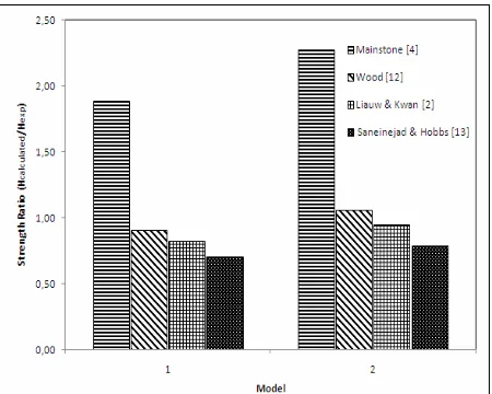
Figure 7 shows the comparison of the normalized lateral strength calculated using those analytical methods against that of the test results. The figure shows that all the methods, except Mainstone method, produce close estimation of the lateral strength. Thus, in general, those formulas can be used to predict the lateral strength of both AAC infill and Clay infill with good accuracy.
Figure 7. Normalized Lateral Strength by Various Methods
Lateral Stiffness
Table 5 shows initial stiffness of the test models calculated by various methods. The initial stiffness is defined here as precracked stiffness of the test models. The initial stiffness of the unreinforced infill frame is frequently modeled by diagonal compressive strut models which correlate well with effective strut width of diagonal strut length. Paulay et al. [6] and Tomazevic [5] recommend the strut width of one-fourth of diagonal length. However, FEMA 306 [14] recommends a strut width of
ls = 0,175 (λ1hcol)-0,4ld (3)
strut length and λ1 is the infill to frame stiffness
parameters. By using those strut width equations, the computed initial stiffness is as listed in Table 5 (values in the bracket show ratio between calculated values and the test results).
Table 5. Initial Stiffness by Various Methods
Models Test
As shown in the table, for test model 1, the initial stiffness of in-filled frame from the test results is better estimated by FEMA equations than by Paulay’s. On the other hands, for test model 2, Paulay’s equation gives better estimate than the FEMA’s.
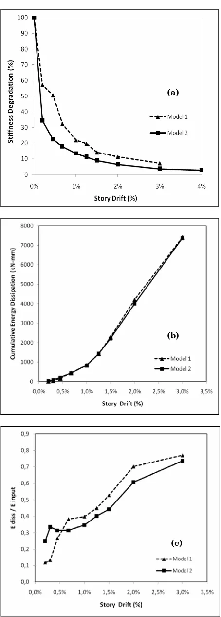
Figure 8a shows degradation of secant stiffness for both test models. For cyclic loading, the secant stiffness at each drift level is computed as the slope of the line connecting the extreme points of the last cycle at the respective drift level. It can be seen from the figure that in general the AAC infill has less stiffness degradation than the clay infill.
Energy Dissipation
Figure 8b shows the cumulative energy dissipation of both test models. The energy dissipated in one load cycle is defined as the area bounded by hysteresis loop produced in that respective cycle. For each drift level, the representative dissipated energy is taken as the smallest in that drift level. It can be seen in the figure that the cumulative energy dissipation of both test models is similar. Figure 8c displays the ratio of energy dissipation to energy input. Again, it can be seen from this figure that test model 1 produces more efficient performance than test model 2. So, in general, test model 1 exhibits better performances than test model 2.
Displacement Ductility Ratio
In seismic design, performance of structure beyond elastic range is usually expressed in terms of ductility ratio. The displacement ductility ratio is commonly defined as the ratio between the ultimate displacement at which the lateral resistance of test model was reduced to 80% of its maximum lateral resistance and the yield displacement. Based on the experimental results, the ductility ratio of each test model is summarized in Table 6.
Table 6. Summary of Specimen’s Ductility Ratio
Description Model 1 Model 2
Forces at first yield of reinf. (kN)
-93.90 -83.70
Displacement at first yield of reinf. (mm)
-7.33 -10.16
Forces at 80% of maximum lateral load (kN)
-85.87 -84,72
Displacement at 80% of maximum lateral load (mm)
-47,6 -62
Ductility, µ 6,5 6,1
confined masonry of µ = 4. This indicates that both test models produce good performance under lateral load simulating earthquake forces.
Conclusions
The behavior of two types of infill materials, namely AAC and Clay units, was experimentally investigated. The test results showed that at failure AAC infill developed strut mechanism in the form of diagonal cracking. On the other hand, clay infill exhibited mode of failure in the form of sliding shear and partial infill crushing. The strength, ductility and cumulative energy dissipation of both specimens exhibited similar behavior throughout the tests. Analytically, the initial stiffness of AAC infill can be best represented by FEMA 306 model, while that of Clay infill can be best represented by Paulay model. In addition, some analytical models available in the literature, such as Wood, Liauw&Kwan and Saneinejad & Hobbs models, can produce close estimate of the lateral strength of R/C frame in-filled with AAC infill or Clay infill. Therefore, those models can be used in the design and analysis of R/C frames in-filled with light weight materials, such as AAC blocks.
In general, although clay infill posses higher initial stiffness, the AAC infill produced less stiffness degradation and demonstrated better hysteretic behavior than the clay infill. Because of that, it can be concluded from this study that AAC block units can provide good behavior of in-filled frame under lateral load simulating earthquake forces. Therefore, these materials can basically be used to replace clay brick units as infill materials for R/C frames built in the earthquake prone region, such as Indonesia..
Acknowledgements
The experimental study reported herein has been conducted as part of research projects funded by the Asahi Glass Foundation (AGF) Japan. The additional financial assistance from the Structural Engineering Laboratory of ITB to fabricate the test setup is also gratefully acknowledged. The experimental work for this research was conducted in Structural Mechanics Laboratory of ITB. The results, opinions and conclusions expressed in this paper are those of the writers and do not necessarily reflect those of the sponsors.
References
1. Al-Chaar, G., Issa, M., and Sweeney, S., Behaviour of masonry-infilled nonductile reinforced concrete frames, Journal of Structural Engineering, ASCE, Vol. 128(8), 2002, pp. 1055-1063.
2. Liauw, T. C., and Kwan, K. H., Unified Plastic Analysis for Infilled Frames, J. Struct. Eng., (a)
(b)
3. Mehrabi, A.B., Shing, P.B., Schuller, M., and Noland, J., Experimental evaluation of masonry-infilled RC frames, Journal of Structural Engineering, ASCE, 122(3), 1996, pp. 228–237.
4. Mainstone, R., On the Stiffness and Strength of Infilled Frames. Proceedings of the Instituition of Civil Engineers, Supplement, volume 48, 1971, pp. 57-90.
5. Tomazevic, M., Earthquake-Resistance Design of Masonry Building, Imperal College Press, London, 1999.
6. Paulay, T. and Priestley, M.J.N., Seismic Design of Reinforced Concrete and Masonry Building, J. Wiley and Sons, NY, 1992.
7. Hoedajanto, D., Imran. I., and Aryanto, A., Experimental study of AAC Hebel floor and wall panel, Proceeding of 2007 HAKI Conference: Seismic Construction in Indonesia, Jakarta – Indonesia, 21 - 22 August 2007.
8. Tanner, T.E., Varela, J.L., Klingner, R.E. Brightman, M.J., and Cancino, U., Seismic Testing of Autoclaved Aerated Concrete Shearwalls: A Comprehensive Review, ACI Structural Journal, ACI, Vol. 102(3), 2005, pp. 374-382.
9. Purwono, R., Tavio, Imran, I., and Raka, I.G.P.,
Indonesian Concrete Code for Buildings (SNI 03-2847-2002) with Commentary, ITS Press, Surabaya, Indonesia, 2007.
10.ACI Committee 318, Building Code Requirements for Structural Concrete and Commentary (ACI 318-08), American Concrete Institute, Farmington Hills, MI, 2008.
11.ACI Committee 374, Acceptance Criteria for Moment Frames Based on Structural Testing and Commentary (ACI 374.1-05), American Concrete Institute, Farmington Hills, MI. 2005.
12.Wood, R.H., Plasticity, Composite Action and Collapse Design of Unreinforced Shear Wall Panels In Frames, Proceedings of the Instituition of Civil Engineers. (Part 2), 65, 1978, pp. 381– 441.
13.Saneinejad, A. and Hobbs, B., Inelastic design of infilled frames, J. Struct. Eng. ASCE, 121(4), 1995, pp. 634–650.