AUTOMATIC EXTRACTION OF BUILDING ROOFS
FROM PICTOMETRY’S
ORTHOGONAL AND OBLIQUE IMAGES
Yandong Wang
Pictometry International Corp.
Suite A, 100 Town Centre Dr., Rochester, NY14623, the United States [email protected]
Commission III, WG III/4
KEY WORDS:
Photogrammetry, Extraction, Building, Image, Edge, Automation.
ABSTRACT:
Automatic extraction of buildings from digital images aims at detection of buildings from digital images and reconstruction of roof structure automatically. At Pictometry, more than 30 million images are captured every year and how to extract the useful information of objects on the ground from the existing image library for various applications is a big challenge we face now. In this paper, an automatic approach for extraction of building roof from digital orthogonal and oblique imagery is proposed. The proposed method uses image processing technique to derive the accurate 3D structure of building roof for accurate roof measurement, 3D modeling, computation of building footprints, etc. It consists of three major steps, i.e. extraction of roof corner and ridge points from the images, automatic matching of roof corner and ridge points between orthogonal and oblique images and grouping of the matched roof points to create roof facets. In this study, the modified Moravec operator is used to extract feature points from digital images. To find roof points which cannot be extracted by the point extractor, edge information is also extracted. Due to the nature of roof points, especially corner points and the difference between orthogonal and oblique images, a feature-based image matching technique is used to derive 3D information of roof corner and ridge points, instead of area-based matching. To match roof points correctly, edges associated with a corner or ridge point and their properties are used. After 3D roof points are generated, roof points belonging to the same roof facet are grouped together by using their spatial relations. Once points belonging to the same facet are found, a surface is fitted to the points and outliers can be removed during this process.
1. INTRODUCTION
3D modeling of buildings has many applications in different areas such as 3D city modeling, communication, insurance, urban planning, etc. Automatic extraction of buildings from digital images has received significant attentions from both computer vision and photogrammetry over decades and there are a number of methods developed by researchers in these fields. The early research was focused on the extraction of buildings with simple structures (rectangular shape) (Huertas and Nevatia, 1988; Fua and Hanson, 1991; Dang et al, 1994; Roux and McKeown, 1994; Lin et al, 1995). Some approaches dealing with buildings with complex structures were developed in Lang and Förstner (1996), Henricsson (1996) and Taillandier and Deriche (2004). Recently an approach for extraction of building façade has been developed by Xiao et al (2010).
Pictometry started to capture geo-referenced imagery using its proprietary imaging system more than a decade ago. Currently more than 30 million of both vertical and oblique images are captured every year at Pictometry and the number still increases every year. One big challenge we face is how to extract useful information from the existing image library for different users. In this paper, an approach for automatic extraction of buildings from both vertical and oblique imagery is presented. The approach focuses on the reconstruction of building roof using image processing methods for different applications such as 3D city modeling, insurance and urban planning. It consists of three major steps, i.e. automatic extraction of features and generation of topological relations between features, matching of 2D features to derive 3D features and grouping of 3D features to generate roof facets. In the following sections, a
building model for automatic building extraction will be described in section 2. The details of feature extraction, matching and grouping will be given in section 3. Some testes results will be given and discussed in section 4.
2. BUILDING MODEL AND EXTRACTION STRATEGY
Various building models have been developed for building extraction based on the type of buildings to be extracted and the resolution of images to be used. They range from using simple geometric constraints such as rectangular shape to the use of complex 3D geometric constraints for extraction of buildings with complex structures. Extraction strategy largely relies on the model to be used for building extraction. It can be data-driven, model-driven or hybrid. In a data-driven strategy, extraction usually starts from extraction of generic features from imagery such as points and lines. 3D features are generated by matching 2D features from overlapping images and buildings are reconstructed by grouping 3D features. A review on building models, building extraction strategy and performance of some existing methods can be found in Mayer (1999).
and the features extracted from different images are matched to create 3D features. 3D features are then grouped to form roof primitives – facets. Finally they are grouped together to create a complete roof structure.
3. AUTOMATIC EXTRACTION OF BUILDINGS
3.1 Feature Extraction
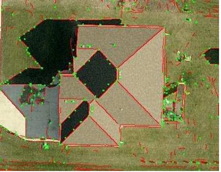
Based on the building roof model, two types of features, i.e. points and edges, are extracted from both vertical and oblique images for reconstruction of buildings. There are numerous operators for extraction of points and edges and each has its advantages and disadvantages. In this study, a simple point operator - the modified Moravec operator is used to extract point features for the efficiency of processing while edges are extracted by using the Canny operator. The Canny operator is famous edge detector and it has good localization accuracy and less sensitive to image noise. An example of feature extraction by using Moravec and Canny operators is shown in Figure 1. As can be seen, most features are extracted correctly, but some false features are detected as well. These false features should be removed before image matching in order to derive reliable 3D features.
Figure 1. Extracted points (green) and edges (red)
3.1.1 Preprocessing of Features One common problem
of the point operators is that they cannot extract all the feature points from the image due to the complexity of aerial images and at the same time some of the extracted feature points may not be true features. Thus, false feature points should be eliminated and missing point features should be added before generating 3D features. In addition, the extracted edge pixels should be traced to form edge segments. A roof corner is the intersection of two or more than two roof lines. Most false point features can be removed by applying this constraint to the extracted feature points. The extracted edge pixels are traced based on their proximity and similarity in edge orientation. Smooth and straight edge segments are generated by using a split-and-merge operation to the traced edge segments. Most noisy edge segments can be removed by this operation.
To find missing point features, close line pair segments are first selected and their spectral properties in their flanking areas are then compared. They belong to the same roof facet and their intersection is computed if they have similar spectral property.
If the computed intersection is not in the list of extracted point features, it is then added to the list.
3.1.2 Removal of Gutter’s Effect Gutter is an important
feature of a building roof. It is visible in a high-resolution aerial image and has two parallel edge segments with approximate equal length in the image, as shown in Figure 2. The existence of double edges at roof gutters may yield mismatch points and thus reduce the reliability of roof reconstruction. Therefore, only one edge should be used in the reconstruction. In order to keep the accuracy of computed roof area and pitch, the inner line should be used and the outer one needs to be removed. To eliminate the outer edge of gutters, all parallel edges with opposite edge direction near roof boundary are examined and only those with the distance between two parallel edges within a given threshold are selected. Their distances to the center of the building are then computed and the edge with larger distance is removed.
(a) Image edges before removal of gutters
(b) Image edges after removal of roof gutters
Figure 2. Removal of roof gutters
3.1.3 Computation of Feature Properties and relations
of feature points include geometric and radiometric properties. The geometric properties of a feature point include its location in the image, the number of edges which intersect at the point and their spatial directions, angles between the edges and the locations of points which connect with the current point. The radiometric properties include the average intensity value between two edges.
The feature relations include topological relations between edges and between points and edges. Intersecting edges are arranged clockwise based on their spatial orientation. Their relation can be represented by left and right while the relation between a point and an edge can be described by connect-to.
3.2 Matching of Roof Points
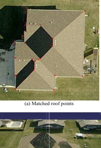
After feature points are extracted from both vertical and oblique images and their properties and relations are determined, they are matched to generate 3D feature points. Due to the nature of oblique images, the background around a feature point is quite different in different images. Therefore a feature-based image matching method instead of an area-based image matching is used to find the corresponding feature points on the overlapping images. Each feature point is represented as the intersection of two or more than two edges. Corresponding feature point in the overlapping images should be the intersection of corresponding edges if they are visible in the images and are extracted. Thus, the criteria used in the image matching are the spatial directions of edges associated with the feature point and the gray value between two edges. The point with minimum difference of edge direction and gray value is treated as the corresponding point. Since image matching is done among the vertical and four oblique images with different view directions, usually a feature point can be matched on more than three images. Once a point is matched successfully, its coordinates in ground coordinate system are computed by the least square adjustment method. After the ground coordinates are calculated, the residuals of the point can be computed on all the images and the points with large residuals are treated as unreliable point and removed, and the matched points on the remaining images are used to compute the point’s coordinates again. Finally, the point’s elevation is checked against the terrain’s elevation around the point and the point is kept if the elevation difference is larger than the given threshold. One example of matched roof points is shown in Figure 3.
(a) (b)
Figure 3. Matched roof points (a) matched roof points on nadir image (b) matched roof points on oblique image with North
view
3.3 Grouping of Roof Points
In grouping, the generated 3D feature points belonging to the same roof facets are grouped together to create roof facets. The
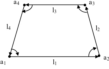
grouping starts with any feature point and one edge associated with the point as point a1 and edge l1 shown in Figure 4. It proceeds to the next point using the relation connect-to and finds the next edge by relation right (a2 and l2). This process is repeated until it reaches at the starting point. Once all feature points of the facet are found, a plane is fitted to the points by the least squares adjustment. If the facet has more than three roof points, the elevation of every point will be checked against the fitted plane. The elevation of a point will be corrected if the difference between the fitted surface and the point is larger than the given threshold. In this way, all roof facets are created.
Figure 4. Grouping of feature points
4. TESTS RESULTS
To test the developed approach, a number of images have been tested. The test images are color image data captured by Pictometry’s imaging system. Each group of test images have one nadir image and four oblique images with different view directions, i.e. north, south, east and west. The nadir images have a GSD of 10 cm (4”) while the GSD of oblique images is between 10 cm and 13 cm within the image. The areas covered by the test images are typical residential area and most buildings in the areas are two story residential buildings. Some of the test results are listed in Table 1.
No. of
The first test building in the table is a residential building with hip roof as shown in Figure 5. This is a typical simple residential house. The reconstruction of this type of building is relatively easy since they have very simple roof structure. The only issue with this building is that there is a deck on one side of the building and there are some decorations around the building. This needs to be dealt with carefully. The result shows that four roof facets were extracted successfully.
The second test building is a two story residential building with combined hip and gable roof structure. The roof has ten roof facets and each has a reasonable size. Most facets have simple
Figure 5. Match points of hip roof (red dots)
regular shape except one of the gable roofs above the garage which has seven vertices and the distance between some of the vertices is very small as shown in Figure 6. There are no trees near the building except some shadow and a deck in the backyard. As can be seen, the building roof extraction was quite successful and all roof points were extracted and matched correctly (red dots) and all roof facets were created. The 3D view of the reconstructed building is shown in Figure 6.
(a) Matched roof points
(b) 3D view of reconstructed building
Figure 6. Matched points of complex building roof
Figure 7 shows the extraction result of a building with more complex structure. The building has 15 facets and most of them have reasonable size. Due to the low sun angle the image was captured, there are some shadows cast on the roof which caused some problem for one of the hip roofs above the garage. As noticed, two points (green dots) were not matched since they are not visible in three oblique images. As a result, two facets on both sides of the valley line between these two points (green line) were not created.
Figure 7. Building reconstruction of complex building
To investigate the applicability of the developed approach, a large residential building was tested. The building has four units under one roof and very complex roof structure. There are 6 different shapes of facets and 30 roof facets totally. The most complex facet has 10 vertices and adjoins 8 different facets. As shown in Figure 8, most roof points were extracted except two and 26 out of 30 roof facets were reconstructed successfully. The reason that four facets were not extracted is that two ridge lines were not extracted due to the low contrast along the ridge lines (blue lines). This caused the gable roof facets on both sides of the ridge lines not generated correctly. Two points (green dots) were not extracted because the valley line between them was not extracted by the Canny operator due to the low contrast.
Figure 8. Building reconstruction of large complex building missing
5. CONCLUSIONS
A novel approach for building reconstruction using both vertical and oblique images captured by Pictometry’s imaging system is presented in this paper. It uses a building model which consists of three basic parts, i.e. points, lines and facets and their relations and a bottom-up strategy to reconstruct building roofs. Both the Moravec and the Canny operators are used to extract point and edge features. 3D features are generated by feature-based image matching and are grouped by using topological relations between features to generate roof primitives – facets. The method has been tested on different buildings in different images and test results show that building roofs can be reconstructed correctly if roof lines (eaves, ridge and valley lines) can be extracted properly.
6. REFERENCES
Dang, T., Jamet, O. and Maitre, H., 1994. Applying perceptual grouping and surface models to the detection and stereo reconstruction of buildings in aerial imagery. In: IAPRS, Vol. XXX, pp. 165-172.
Fua, P. and Hanson, A.J., 1991. An optimization framework for feature extraction. Machine Vision and Application. Volume 4, pp. 59-87.
Henricsson, O., 1996. Analysis of image structures using color attributes and similarity relations. PhD Thesis, Mitteilung,59, Institut für Geodäsie und Photogrammtrie, Zürich, Switzerland.
Huertas, A. and Nevatia, R., 1988. Detecting buildings in aerial images. Computer Vision, Graphics and Image Processing, Volume 41, pp.131-153.
Lang, F. and Förstner, W., 1996. Surface reconstruction of man-made objcts using polymorphic mid-level features and generic scene knowledge. In: IAPRS, Volume XXXI, pp. 415-420.
Lin, C., Huertas, A. and Nevatia, R., 1995. Detection of buildings from monocular images. In: A. Grün, O. Kübler, and P. Agouris (eds.), Automatic Extraction of Man-Made Objects from Aerial and Space Images, pp. 125-134. Birkhäuser Verlag, Basel.
Mayer, H., 1999. Automatic object extraction from aerial imagery – a survey focusing on buildings. Computer Vision and Image Understanding, Volume 74, issue 2, pp. 138-149.
Roux, M. and McKeown, D.M., 1994. Feature matching for building extraction from multiple views. In: proceeding of DARPA Image Understanding workshop, pp. 331-349.
Taillandier, F. and Deriche, R., 2004. Automatic building reconstruction from aerial images: a generic Bayesian framework. In. IAPRS, Volume XXV, Part 3, pp. 343-348.