NEW INSTRUMENTS FOR SURVEY: ON LINE SOFTWARES FOR 3D
RECONSTRUCTION FROM IMAGES
E. Fratus de Balestrinia
, F. Guerra b
a
Università IUAV di Venezia, Laboratorio di Fotogrammetria Circe, S. Croce 191, 30135 Venezia –
elenafratusdebalestrini@gmail.com
b
Università IUAV di Venezia, Laboratorio di Fotogrammetria Circe, S. Croce 191, 30135 Venezia – guerra2@iuav.it
KEY WORDS: 3d scanner, photogrammetry, 3d modeling, survey
ABSTRACT:
3d scanning technologies had a significant development and have been widely used in documentation of cultural, architectural and archeological heritages. Modern methods of three-dimensional acquiring and modeling allow to represent an object through a digital model that combines visual potentialities of images (normally used for documentation) to the accuracy of the survey, becoming at the same time support for the visualization that for metric evaluation of any artefact that have an historical or artistic interest, opening up new possibilities for cultural heritage's fruition, cataloging and study. Despite this development, because of the small catchment area and the 3D laser scanner's sophisticated technologies, the cost of these instruments is very high and beyond the reach of most operators in the field of cultural heritages. This is the reason why they have appeared low-cost technologies or even free, allowing anyone to approach the issues of acquisition and 3D modeling, providing tools that allow to create three-dimensional models in a simple and economical way. The research, conducted by the Laboratory of Photogrammetry of the University IUAV of Venice, of which we present here some results, is intended to figure out whether, with Arc3D, it is possible to obtain results that can be somehow comparable, in therms of overall quality, to those of the laser scanner, and/or whether it is possible to integrate them. They were carried out a series of tests on certain types of objects, models made with Arc3D, from raster images, were compared with those obtained using the point clouds from laser scanner. We have also analyzed the conditions for an optimal use of Arc3D: environmental conditions (lighting), acquisition tools (digital cameras) and type and size of objects. After performing the tests described above, we analyzed the patterns generated by Arc3D to check what other graphic representations can be obtained from them: orthophotos and drawings. The research's result is a critical analysis of the software's potentialities, with an indication of the areas in which it is possible an effective and alternative use to other methods of survey.
1. INTRODUCTION: SOFTWARES FOR 3D RECONSTRUCTION FROM IMAGES
In recent years, great strides made in the field of computer vision allowed to produce algorithms to reconstruct approximated three-dimensional representations from simple sequences of digital photographs. Thanks to the extraordinary development of digital cameras occurred in these years, it is possible to create a large number of high quality photos in a short time and, thanks to special softwares, anyone can construct approximate representations of 3D scenes.
Softwares for 3D reconstruction from images generally exploit the dense stereo matching techniques, which allow to extract 3D information from simple images not calibrated. The principle on which these systems work is similar to the photogrammetric approach: from a series of correspondences between images it is dated back to the cameras parameters and position in space of points of correspondence. At first, the softwares automatically find the correspondence points, thanks to which they can calibrate the camera; then they establish a pixel-pixel correspondence between all the images (a “dense” process) to obtain a depth map (range map) from each image.
2. ARC3D
Arc3D is a freeware software of automatic 3D reconstruction
2.1 Principles of functioning of dense stereo matching softwares
Since dense stereo matching systems require a lot of computing power, the software runs as a service on-line: data are sent to a server which processes it on a cluster of machines. Once registered as a user, through a program downloaded from the website, you can send a set of photos depicting the object of interest: the data are processed and the user is sent an email with a link to the results, that the user can then display and process.
Stereo matching algorithms are passive 3D reconstruction algorithms that derive the depth information by observing the differences between two or more images. Generally they fall into two phases:
− matching: search for correspondence points between images
− reconstruction: from every match they obtain the 3D point associated with it
Capture stage
As in photogrammetry, in capture stage operator acquires a series of images of the object to be surveyed: the images must obviously cover the whole object, so that we can reconstruct the whole geometry.
This is the only one of three phases in which the operator has to intervene. The images can generally be acquired by non-metric cameras (so to everyone) and it is not necessary to adopt particular patterns of capture: the operator must acquire the frames moving around the object so as to cover it all.
From this stage, the operator no longer has to intervene, and further processing leading to the construction of the model is carried out automatically.
Automatic orientation stage
During the automatic orientation stage, systems based on dense stereo matching techniques have to extract the positions in correlation points between the images. Matching methods may be: called image patch, with its counterpart in the other image. The feature based methods are more complicated and involve the
extraction of features that are included in limits on different scales, with resulting comparison based on correlation of features such as size and shape. This type of correlation requires techniques from the reality of artificial intelligence.
The symbolic based methods are an hybrid solution that involves some combination of the two previous methods: after
correlations have been found in a pre-analysis stage, they are coupled with area-based methods epipolar geometry is reconstructed and it is possible to give life to the projective structure of the scene. Each image is paired with the previous one and each new projective camera is calculated in the projective structure of the previous pair. Once all images have been paired, it is then possible to know the cameras location in space but also the position of individual points of correlation into the perspective reference system of the images. Then all images are recorded in a single perspective reference system (every single image is in a certain reference system that is is given by the position of the camera, which was acquired, in the space) and finally the perspective reference system is transformed into the Euclidean reference system (three dimensional).
Dense matching stage
Once the auto-orientation step is finished, the geometry of the scene is reconstructed and it is in a new Cartesian reference system in three dimensions; correlation points are the basis for the construction of the three-dimensional model of the object and they are necessary in the reconstruction stage. Even at this stage all the operations are performed automatically, without operator intervention, and the final result is the three-dimensional model of the object of interest.
The correlation points identified in the previous phase are generally not quite "dense" to rebuild the object, but they have to become trick: this process is called dense matching.
In the dense matching stage, it is performed a pixel-pixel similar enough to be analyzed in pairs. Then images are scaled to reduce the workload on the server.
Figure 2. Comparison between couple of images With characteristic points they form the triples of images: from a series of triple the system is able to calculate the intrinsic data of the three cameras corresponding to the three images, in addition to the 3D points in the perspective reference system. All the triplets are possible candidates for self-calibration. This step is repeated many times until all possible combinations have been tried.
Figure 3. Formation of triples
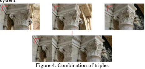
Then the triples are combined to create a single set of data: since each triple is calculated relative to her reference system (from the camera position in space), it is necessary to transform data from all the triples so as to bring them in same reference system.
Figure 4. Combination of triples
In the next step the system transforms the 3D points from their perspective space to the three-dimensional Euclidean.
Finally, when all data is available, they should be rescaled to their original size. The easiest way to do this is to scale all the intrinsic data of the camera iteratively, until to get to the original size. The positions of 3D points do not change during this phase and to minimize errors and improve data quality, the characteristic points are searched at every level of detail. At the end of the reconstruction we obtain a set of cameras and 3D points. Generally the number of these points is not sufficient for the scene reconstruction: in order to obtain more information, the system performs a process called dense matching that, in the end, also returns information on the accuracy of the depth of the image point and therefore on its 3D position .
At this stage the points obtained during the comparison of couples have to become trick in order to reconstruct the scene accurately.
The dense matching process is based on an algorithm that performs the comparison of all possible pairs of a sequence of images; the results of the comparison are combined into a depth map for each image using an algorithm that controls the
indicate the confidence level in the 3D reconstruction, are part of the output data that are sent to the user.
Figure 5. The dense matching
Initially, the algorithm obtains an approximation of the volume of the 3D scene. This can be calculated from points obtained from the comparison. The initialization of the volume continues through the construction of the true form, calculating the photo-consistency between dots in different images.
The depth maps are computed by connecting the matching points and approximating them through the representation of a surface suitable for display. In order to obtain a spatial coherence for the surface, the depth map is spatially interpolated using a parametric surface model.
In a first stage the object is defined as a connected region in space: cleaning filters remove regions too small and those that cause noise on the surface. Subsequently, the surface is smoothed and discontinuities are interpolated.
The smoothed surface is then approximated by a triangulated mesh to reduce the geometric complexity.
4. TESTING PHASE
4.1 Organization of the work
Once analyzed the functioning of the software we have passed the testing phase itself. There have been identified certain types of objects, different in size and morphology, and of these there were made models for mesh with Arc3d. Parallel scans with laser scanner were performed of the same objects. This is because, to verify the metric and geometric accuracy of models made with Arc3D, it was decided to perform a comparison of surfaces: the result obtained by the laser scanner point clouds is a model for mesh such as those that are generated by Arc3D.
• Once they are built models from Arc3d and from laser scanner, it was performed the compare; the process used was as follows: use of the laser scanner model as a comparison (considered "safe" and correct in metric therms)
• scaling of the Arc3D model on the laser model to bring it to the same scale
• registration of the two models in the same reference system (the models are in two different reference systems given, one from the cameras position used for image acquisition, the other from the of the laser scanner posotion at the time of acquisition) by ICP (Iterative Closest Point) algorithm that minimizes, point for point, the distances between the surfaces of the models, using software to manage data from 3D scanning (Geomagic)
• evaluation of the maximum error of the model made with Arc3D
• indication of a possible scale of restitution for the model
The tests were performed on the following categories of objects: • archaeological finds
• architectural elements • bas-reliefs and statues • facades and entire buildings
4.2 Archaeological finds
As for the archaeological finds, it was not possible to perform the scans with 3D scanner, then the models built with Arc3d were evaluated only from a visual point of view. The findings, that have a small and medium-size, are kept in the Archaeological Museum of Altino (Venenzia). The images were acquired with a digital camera type reflex with 6megapixel and model generated by Arc3d were more than satisfactory, at least from a visual point of view.
4.3 Architectural elements
On architectural elements, however, it was possible to make the comparison between models and therefore the accuracy of models generated by Arc3d was evaluated by a metric point of view.
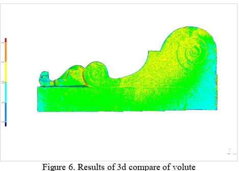
The first model under investigation is a volute from the so-called ground portal located in the lobby of the headquarters of IUAV Tolentini (Venice), of which we already have 20 point clouds, acquired with a triangulation range camera Minolta Range 7. For the construction of the model with Arc3d were acquired 58 images, divided into 4 series, with a compact camera with 6 megapixel Nikon L11. Starting from the 4 image sequences were constructed 4 partial models which, after, were registrated in the same reference system: the registration was done through a software with a rototranslation obtained by an ICP (Iterative Closest Point) algorithm.
For the purposes of comparison, the Arc3d model was scaled on the model generated from point clouds; after the two models have been recorded in the same reference system (that of the model generated by the laser data) and finally it was performed the comparison between the two. By a software it was performed an automatic measurement of the distance of any point on the surface of the test (model Arc3d) from the surface of the reference object (model from laser data). This procedure was subsequently used for all the models.
The results of the comparison between the two models of the volute were more than satisfactory: it was found that the minimum gap between the surfaces is 0.1mm for up to a maximum of 2.5 mm, with a possible scale of restitution equal to 1:10.
Figure 6. Results of 3d compare of volute
With regard to the architectural elements, it was also built a model of a capital placed in Campiello of Scuola Grande of San Giovanni Evangelista (Venice): it was no comparison with the laser data, but the positive result of 3D reconstruction was used to highlight some of the potentials of the system Arc3d: the capital is placed at a height of about 2.5 m above from the ground, with morphology and dimensions, which involve the use of a triangulation range camera for a possible 3D reconstruction. Generally triangulation systems, such as time of flight, need to be established to support such as tripods and so on. But above all, to perform the scans, they must be placed at a close distance from the object, which in this case was not possible because of the position of the capital. In this case, the ability to capture images to construct a 3D model, it proves very useful because the camera can be hand held, photographs can be taken by moving around the object and it is not necessary to hold a close distance to the object.
4.4 Bas-relief and stautes
On bas-reliefs and statues we performed several tests, that have shown other positive features of the system Arc3d. From what we read in the instructions for use contained on the Arc3d site (http://homes.esat.kuleuven.be/visit3d/webservice/v2/manual2/s iframes.html) it is not recommended to take pictures of plans objects or similar to plans, such as bas-relief or engravings, since these scenes do not contain enough information for camera calibration. As we will see, the tests have partly contradicted these claims.
Figure 7. Results of 3d compare of bas-relief
The second model built is the entrance portal of the headquarters of IUAV Tolentini (Venice): the portal, in white stone, is characterized by a lightly embossed surface with a phrase carved in the center (Verum Ipsum Factum). In this case, according to information contained in the Arc3d site, reconstruction would not have happened, because of the lack of information for camera calibration. The system is however able to perform the reconstruction, and as shown in the pictures, also the writing is legible. For the comparison was acquired a single point cloud with a time of flight laser scanner Riegl LMS-Z390i, while for Arc3d 44 images were acquired with a camera type reflex Canon EOS 300D with 6 Mpixel. The result of the comparison, given the low expectations, it was also good in this case: the average gap between the two surfaces was found to be approximately 6 mm, with a possible scale of restitution equal to 1:20.
Figure 8. Results of 3d compare of portal
Finally, models were constructed of a statue and a bas-relief, both located on the front of two churches, at heights that do not allow the approach of an operator (unless the use of stairs or elevators). For these models it has not been possible to make the comparison with data from laser but, again, the positive result of reconstruction, has shown the usefulness and convenience of being able to use a camera as a means to reconstruct 3D scenes of objects placed in uncomfortable positions to reach.
4.5 Facades and entire buildings
The last category of scanned objects include facades and entire buildings: as you can imagine, the results expected could not be to the levels of those obtained till now, given the large size, but the service Arc3d worked fine again.
We initially constructed the model of the facade of a small church in Venice, San Nicolò dei Mendicoli: it has not run a comparison with data from laser scanner but the construction of the model has served to demonstrate what is already imagined. To obtain a complete covering of the front in each frame it was necessary to keep a certain distance from the building (approximately 7 / 8 m), a distance that has involved the loss of detail on the images and therefore also in the model.
As you can see, the model describes the general geometry of the facade but during the reconstruction we have lost all details, such as the decorations of the capitals, the statues in the niches, moldings on portals, etc..
The 3D reconstruction of the so-called House of the Executioner (School of Varoteri) in Venice, was used to determine whether you can perform a full 3D survey of an entire building with the Arc3d system and therefore its possible application to the architectural scale.
Were initially acquired 67 images of the building with a reflex camera with 6 Mpixels and after they were acquired 4 point clouds by time of flight laser scanner Riegl LMS-Z390i. Once built the two models, the comparison was performed according to the procedure used till now, that is through automatic measurement of the distance of any point on the surface of the test object (model Arc3d) from the surface of the reference object (model from laser scanner): the comparison showed an average gap of 20 mm between the two surfaces, with peaks of about 50 mm towards the edges due to the perspective distortion of images. It was possible to give a scale of restitution equal to 1:100.
Figure 9. Results of 3d compare of the School of Varoteri
Since the comparison of surfaces gaves results not fully satisfactory, it was also performed another type of test: orthophotos of a facade were constructed based on the data from laser scanner and Arc3d, and these have been compared. This is to verify if the geometry of the model generated from Arc3d was still correct.
• The operating procedure followed was as follows: choice of an elevation (north elevation)
• extraction of point clouds of chosen elevation by the two models (Arc3D and laser scanner)
• acquisition of an image of the selected elevation • orientation of the image (with software NM3) to
derive the parameters of the DLT (Direct Linear Transformation) which are used to apply color to the clouds of points: Pointools) with a resolution of 1 pixel per cm • comparison of orthophotos (with Photoshop software)
by the removal of the lasert orthophoto from the Arc3d orthophoto
The comparison between the two orthophotos showed that there is no substantial difference between the geometries of the two models: the white parts indicate areas in which the two orthophotos do not match. The distribution of the white is uniform and this indicates that there are no areas where there is a substantial difference between the two models.
Figure 10. Results of comparison beetween orthophotos
Finally, after tests carried out on the front of the School of Varoteri, we can say that in the case of medium to large buildings the software Arc3D can be effectively used for the restitution of elevations.
In this case, the software Arc3D can be a great help especially as regards the restitution of the tops of elevations, which generally are not easily accessible when you run a survey with the direct method.
5. CONCLUSIONS
On the basis of tests carried out on different objects by type and size, we can draw some important conclusions. For small objects, such as architectural elements or archaeological finds, the online service Arc3D can validly be used as a tool of survey. The precision obtained is between 0.1 mm and 2 mm and this implies a possible scale of restitution that ranges from 1:1 to 1:10, suitable for the survey of detail.
Thanks to the precision obtained, we can legitimately claim that Arc3D, with small objects, can substitute a laser scanner and can be used as a tool of survey from professionals in the field of architecture and cultural heritage in general.
This conclusion is crucial, especially when you consider that the field of cultural heritage is characterized by a continuing lack of funds for research, documentation and restoration. Surveying with traditional instruments implies the presence of specialists and, especially, the use of instruments that have a cost outside the scope of an individual that, sometimes, a public body. The possibility of using an instrument of relief that have no cost becomes a big advantage in this area and may open new way for understanding and documentation of cultural heritage.
First, the tests show that, on objects at an architectural scale, we can obtain accuracies that are around 2 cm and the data is very good, because it allows a restitution to a scale of 1:100. The limit of Arc3D, in this case, is that large objects need to be taken from a distance to be completely figured but in this way you lose the level of detail. The problem could be solved by using high-resolution camera, but the service imposes a limit of 6 Mpixel as maximum resolution of images to be sent, this is because a large number of high-resolution images can cause problems to the server in data management.
In the case of large buildings, it can be concluded then that the automatic reconstruction service Arc3D can be used as a tool of survey for restitutions till to a scale of 1:100 but it can not survey, to learn how to work with data similar to those of the laser scanner and learn, then, methodologies and techniques for building three-dimensional models for mesh.
Finally, for large buildings, the service can be used, by the students, during the project stage: having the ability to extract the point cloud from models or to build orthophotos of facades, students can autonomously restitute, to a scale compatible with the level of detail given by Arc3D, elevations of entire buildings. Again, the use of a tool with no cost is essential. Finally, the freeware software of automatic reconstruction from photographs Arc3D, is a very useful tool for professionals in architecture and cultural heritage in general and for students of the Faculty of Architecture.
6. BIBLIOGRAPHY
M. Docci, D. Maestri, Manuale di rilevamento architettonico e
urbano, Editori Laterza, Roma, 2009
G. Bezoari, C. Monti, A. Selvini, Misura e rappresentazione, Casa Editrice Ambrosiana, Milano, 2001
C. Monti, F. Guerra, C. Balletti, G. Galeazzo, Capitolato speciale d'appalto per l'esecuzione di un rilievo in forma
numerica alla scala 1:50, QuadernIUAV.12.2000, Venezia,
2000
L. Sacchi, L’idea di rappresentazione, Edizioni Kappa, Roma, 1994
R. Migliari, Frontiere del rilievo. Dalla matita alle scansioni 3D, Gangemi Editore, Roma, 2002
D. Marini, M. Bertolo, A. Rizzi, Comunicazioni visiva digitale.
Fondamenti di eidomatica, Addison Wesley, Milano, 2002
G. Guidi, A. Beraldin, Acquisizione 3D e modellazione
poligonale. Dall'oggetto fisico al suo calco digitale, Edizioni
Poli Design, Milano, 2004
L. Menci, F. Ceccaroni, Fotogrammetria digitale
C. Balletti, F. Guerra, Fregonese, Monti, Appunti di fotogrammetria
A cura di T. Fiorucci, Metodologie innovative integrate per il
rilevamento dell'architettura e dell'ambiente, Ricerca Cofin
2002, Gangemi Editore, Roma, 2005
C. Balletti, F. Guerra, P. Vernier, La memoria digitale della forma geometrica: scanner 3d e fotogrammetria digitale per la realizzazione di modelli virtuali, per la riproduzione, per la
conservazione e per la riattualizzazione di oggetti, in Atti 12°
Conferenza Nazionale ASITA, L’Aquila 21 – 24 ottobre 2008
A. Adami, F.Guerra, P. Vernier, Laser scanner and
architectural accuracy text, in Proceeding of CIPA 2007 XXI
Internationa al Symposium "Anticipating the future of the
G. Bitelli, Moderne tecniche e strumentazioni per il rilievo dei
beni culturali, in Atti VI Conferenza Nazionale ASITA,
Perugia, vol. 1, IX-XXIV
V. A. Girelli, Tecniche digitali per il rilievo, la modellazione tridimensionale e la rappresentazione nel campo dei beni
culturali, Tesi di Dottorato in Scienze Geodetiche e
Topografiche, Università di Bologna, Relatore G. Bitelli
J.-A. Beraldin, M. Picard, S.F. El-Hakim, G. Godin, L. Borgeat, F. Blais, E. Paquet, M. Rioux, V. Valzano, A. Bandiera, Virtual reconstruction of heritage sites: opportunities & challenges
created by 3D technologies, published at The International
Workshop on Recording, Modeling and Visualization of
Cultural Heritage. May 22-27, 2005. Ascona, Switzerland. NRC 48100
J.-A. Beraldin, M. Picard, S.F. El-Hakim, G. Godin, E. Paquet, M. Rioux, V. Valzano, A. Bandiera, Virtual heritage: the cases of the byzantine crypt of Santa Cristina and temple C of
Selinunte,
F.B. ter Haar, P. Cignoni, P. Min , R.C. Veltkamp, A comparison of systems and tools for 3D scanning
Michael Roy, Sebti Foufou, Frederci Truchetet, Mesh
comparison using attribute deviation metric, in International
Journal of Image and Graphics Vol. 4, No. 1 (2004), pp. 1-14
M. Vergauwen, L. Van Gool, Web-based 3D reconstruction
service, in Machine Vision and Applications, vol. 17, n. 6, pp.
411-426, 2006
P. Cignoni, Low cost resources for image synthesis and
image-based modeling, Siggraph 2009
M. Pollefeys, L. Van Gool, M. Vergauwen, F. Verbiest, K. Cornelis, J. Tops, R. Koch, Visual modeling with a hand-held camera, in International Journal of Computer Vision, vol. 59, n. 3, pp. 207-232, 2004
M. Callieri, M. Corsini, G. Ranzuglia, P. Cignoni, Scanner 3D
con hardware low cost e strumenti free/open source, in
Archeologia e Calcolatori, Supplemento 2, pp. 173-180, 2009
N. Snavely, R. Garg, S. M. Seitz, R. Szeliski, Finding Paths
through the World’s Photos, in ACM Transactions on Graphics
(Proceedings of SIGGRAPH 2008) vol. 27, n.3, pp.11-21
N. Snavely, S. M. Seitz, R. Szeliski, Photo tourism: Exploring photo collections in 3D, in ACM Transactions on Graphics (SIGGRAPH Proceedings), 25(3), 2006, 835-846
F. Remondino, 3D reconstruction of articulated objects from
uncalibrated images, in Three-Dimensional Image Capture and
Application V, SPIE Electronic Imaging, Proc. of SPIE 4661, San Jose, USA, 2002
R. Koch, J. F. Evers-Senne, J.-M. Frahm, K. Koeser, Christian-Albrechts, 3D Reconstruction and Rendering from Image
Sequences, in WIAMIS, 2005
C. Beder, R. Steffen, Determining an Initial Image Pair for Fixing the Scale of a 3D Reconstruction from an Image
Sequence, in Lecture Notes in Computer Science, vol. 4174, pp.
3D Structure from Multiple Images of Large-Scale Environments ,vol. 1506, pp. 139-154, 1998
S. El-Hakim, A. Beraldin, Detailed 3D reconstruction of
monuments using multiple techniques, in Proceedings of the
International Workshop on "Scanning for Cultural Heritage Recording . Complementing or Replacing Photogrammetry", Corfu, Greece, 1-2 settempbre 2002, pp. 58-64
A. Beraldin, M. Picard, S. El-Hakim, G. Godin, V. Valzano, A. Bandiera, Combining technologies for cultural heritage
interpretation and entertainment, in Proceedings of "Electronic
Imaging 2005: Conferences Videometrics VIII", San Jose, California (USA) 18–20/1/2005, Vol. 5665, pp. 108-118
IST, Information Society Technologies, First set of open