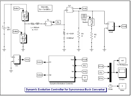
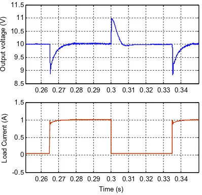
Dynamic evolution control for synchronous buck DC–DC converter: Theory, model and simulation
Teks penuh
Gambar


Dokumen terkait
INTEGRAL-DERIVATIVE (I-D) AND MODULATION-INDEX-CURVE PREDICTION CONTROL TECHNIQUES FOR THREE-PHASE AC-DC BUCK-TYPE CONVERTER WITH SIMPLIFIED VOLTAGE-BASED SPWM.. Field of Study:
Table IV: Output Voltage Regulation Using FSFBC Based On Pole Placement and Optimal. Control
The steady state output voltage of switched inductor boost dc-dc converter and conventional boost dc- dc converter for each duty cycle values are shown in figure 13 to
Therefore, a reliable inverter that can produce a good output voltage is necessary.The main purpose of this paper is to design and develop a dynamic evolution control (DEC) for a PV
Dynamic Modeling and Analysis of Buck Converter based Solar PV Charge Controller for Improved MPPT Performance Venkatramanan D,Student Member, IEEE Department of Electrical Engineering
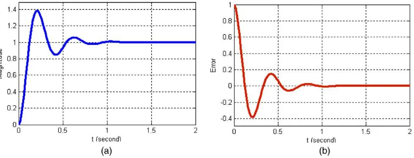
DYNAMIC ANALYSIS In this section various transfer functions describing the step response of the motor speed following step change in com- mand speed and the load disturbance torque
STATCOM step response for change in reactive power The comparison of the load angle and STATCOM output current frequency response characteristics for change in KW are shown in Figs..
14 DOF vehicle Simulink model The output response to be analyzed for step steer and double lane change will be yaw rate, lateral acceleration and roll angle of the vehicle body and
