LOUDSPEAKER FAR-FIELD
EQU
ALTZATION
SYSTEM USING
DIGITAL
SIGNAL
PROCESSOR
Erisman Kriswandhani
Lim!,
Matias H.w.
Budhianthor, F. Dalu setiajitI Audio, Music,
and Electroacoustic Laboratory, Electronics and Computer Engineering Faculfy,
Satya Wacana Christian University Diponegoro 52-60, Salatiga
Email: [email protected], [email protected], [email protected]
ABSTRACT
Sound
reproduction
system
frequency responseat
listener positionin
the far-field
of
a loudspeakeris
not
flat
due
to
the
imperfect frequency responseof
the
loudspeakerand
the room itself. We design an onchip loudspeakerfar-field equalization system at a listener location
ia
aroom
using
TMS320C67l3
Digital
SignalProcessor.
Initially the
system
measures the impulse responseusing
a
MLS
signal.
The minimum-phaseof
measured impulse response isfound
b!
using
Hilbert
transform.Least
meansquare algorithm is then used to calculate equalizer impulse response. Finaily, we used linear phase FIR
filter approach to minimized distortion of its output signal.
The
equalizer successfully decrease thestandard
deviation
of
the
system
magnituderesponse from +6,19
dB to
+3,37dB
at the audio frequency range of20-20000 Hz.Kepvords: equalization,
DSP,
loudspeaker, far-field.1
INTRODUCTION
Sound
reproduction system (consists of
audio amplifier, loudspeaker, and room) frequency
response
at
listenerposition
in
the far-field of
loudspeaker is not
flat.
It
is
caused mai:rlybii
the imperfect frequency responseof
the
loudspeakerand the room itself [1].
A:ralog graphic and
parametric equalizermay mediate this problem. However,
it
requires aspecific skill and equipment (spectrum analyzer) to determine which liequencies need
to
be equalized andit
is
rather complicatedto
do
for a
non-technical people. Furthermore, those equalizers do
not equalize the phase response
of
the system, theyjust equalize the magnitude response. The designed
equalizer equalizes the system automatically using
TMS320C67l3
Digital
Signal Processor (DSp), the magnitude aswell
as phase responseof
the sound reproduction system.,
Least mean
squareis
used
to
solve
theequalization
problem
of
loudspeaker's far-fieldarea. While
it
is not a real-time algorithm,it
could deliver a solution thatis
closeto
Wiener solution.Before
the
implementationof
equalizer hansferfunction,
Hilbert
transform
is
used
to
convertsystem transfer function
to a
minimum-phase systemto
avoid instability. Linear
phase FiniteImpulse
Response(FIR)
filter
approach
andwindowing
is
adaptedto
obtaina
constant groupdelay and
undistortedoutput.
This
filter
has
asymmetric coefficients that lead
to
a decrementof
multiplication operation and memory usage [2].
The
equalization was ableto
improve the standard deviation of system magnitude response at the listener position by more than 50%o.2
N{ODEL,
ANALYSIS,
DESIGN,
AND
IMPLEMENTATION
2.1
Loudspeaker
Far-field
Equalization
Sound
wavefront
at
the
listener
position dependson
the
distancebetween listener
andloudspeaker.
In
loudspeaker'sfar-field which
isapproximately
I
metre away from the loudspeaker,its radiation is omnidirectional and the wavefront is spherical [2].
Iflistener
faces the loudspeaker, the distancebetween
the
loudspeakerto
theright
earis
equalwith
the
left
one.
The
difference
of
binaural perceptionis
ignored
[3],
and the two
listening points at the listener position are identical.The equalization uses a listening room with
an
areaof
25-40 m2that
goesto
fBt-OOZOS-t: standard.The
positioning
of
loudspeaker andlistener
at
that
listening room goes
to
Golden Cuboid standard. Accordingto
those standard, the distance range between loudspeaker and listener is 1,97-
2,49 m, ia the loudspeaker's far-field.Therefore
the
equalizationof
loudspeakerfar-field
responseneed
only
to
consider
theVI-69
i
I
r'i
li
ti fi
$
The 6'h htJrnational Conference on Information
&
Communication Technology and Systemscharacteristic
of
one
listening
point.
This characteristic is determined by the iirpulse response at the listening point.2.2
Least
Mean
Square
Algorithm in
Measuring Equalizer's Impulse
Response
We used least mean square algorirhm
j1
1leequalization by modifying system impulse response so that system output is as close as possible with the
ideal impulse response. The equalization is best
if
the.
squared impulse
responseerror
signal
is mlnlmum.MLS
signal applied
to
measure systemimpulse
response
and
calculated
the
cross-correlation between
the
input
MLS
signal
andreceived
MLS
signal at the listener's position. Theideal
impulse responseis
found from the
auto-correlationof
the inputMLS
signal. There is timedelay
befween thosetwo
MLS
signalswhich
isaccounted
the
distance between loudspeaker andmicrophone.
We
compensatedthe
delay
by
Z samples. The loudspeaker equalization using leastmean square
algorithm
is
shownat
theFigure
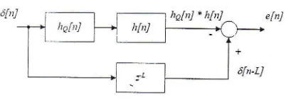
1 [image:2.595.50.251.413.483.2]below.
Figure l. Loudspeaker's far-field equalization system using least mean square algorithm block diagram.
Which
hq[n] is
equalizer's impulse response,l1n/
is
system's impulse
response,6[nJ
is
impulsesignals, e[nJ
is
impulse response's error, and z-r is delay.Equalization enor e[nJ
is
the
differenbe between outputof
serial system(hofn] * h[n]) with
delayed Z-samplesideal impuls
signal
6[n-L]. Equaiizationis
successful when the squareof efnl
is minimum.
Impulse response's
error
canbe
expressedby the following equations:
elnl
=
6hi
- rl
-
(no["J
.
htn])
(l)
The equalization
is
successful when e2 yn1 =0.
The
next step
is
to find
equalizer impulse response hq[nJ so that its convolutionwith
h[nJ issimilar with ideal impuls signal 6[nJ.
The
least mean
square algorithm
isimplemented
in
matrix notation[4].If
hq[n]
has alength
of
M
samples,h[nJ
has
a
length
of
Nsamples, the required length
of
fik-Ll
and e[nJ isM+N-l
samples[2].
The column vector expressionof
h[nJ, he[nJ,
6[nJ
dane[nJ which have
theelements
of
its
samplesare
expressedat
thefollowing equations.
,n
=
(l[ol
hh]
htzl
rlru
-
1l)r
(3)rro
=
qho[oJ
hah]
ha[2]...
halr{
-
1l)r
6
= qaloJ
6t1]
6[2]
.,,dlllt+N-11)t
ds
=
(6[-I]
,r[1
-
r]
612_
d[/lt+lf-I-1])r
e
-
1a[oJ
elr]
elzl
...e[.af*N-1]jr
(4)
(s)
11..,
(6)
(1)
Equation
(2)
canbe
expressedin
matrix form.e
=
6L-
H.he
(8)11
is a
(N+M-l)
by
M
matrix, synthetizedfrom
a column vectorh
so that equal to a convolution between h[nJ andhg[nJ.The
squareof
e[nJ (error
energy) can be expressed at the following equation:E =
er, e=
6zr,6r-
2,hQr,Hr.67+
hQr .Hr
.H.ha
(10)Error
energyis
minimum when
it,s
first derivative with lro is similar to zero.d
(E\
,a-,
=
-?'Hr
't1+z'tf
'H,hq
= 0
(11)
it
isH.ho
lh[0]000\
/r,irl htol
o .., o
\r=lt1z1
hlll
/,tol
o
ltel
\i
\0
i : ". i
l
0 0
fttN_11/
H-t
f
nt
-
rnJ. hq[mJ
(2)
Iti=0
elal
=
dla
- Il
Loudspeaker's Far-field EqualiTation System Using Digital Signal Processor-Erisman K.L.
And the column vector
of
equalizer impulseresponse rs:
hn
=
(Hr.
I{)-',fit,6t
2.3
Hilbert
Transform's
Minimum-phase System
Concept
Most
of
the
measuredroom's
impulseresponse
is
a non minimum-phase. The inverseof
non-minimum phasetransfer function result
in unstable transfer function.The
equalizer transfer functionis
an inverseof
system transfer function thatwill
be equalized, thereforeto
createa
stableequalizer,
the
systemmust
be
convertedto
aminimum-phase system.
A
minimum-phasesystem
G^(d')
has
a magnitude and phase that relates each otherin
aHilbert transform.
rr{tn
1c,"(ei')
l} =
dco.(ei")
(13)Magnitude
of
miaimum-phase system andnon
minimum-phase systemis
equal.Using
thatfact,
we
can
find
the
phaseof
minimum-phasesystem
by
using aHilbert
transform at the naturallogarithm
of non
minimum-phase
system's magnitude.TMS320C6713 DSP doesn't have a specific software function or specific hardware processor to calculate the Hilbert transform, so Hilbert transform
wiil
be found
by
usingthe properly
of
analyticsignal.
For a random real signal
g(t),
analylic srgnalg"(t) canbe expressed at the following equation.
e.(t)
-
s(r)
+.rd(r)
While
d(t)
is Hilbert transform ot g(t).(14)
The should:
G"(j0d)
Fourier transform
of
equation '(14)Therefore Hilbert transform of a random real signal
g(t)
can
be
achievedby
calculating theFourier transform of g(t) (G(j@)), forming G"Qa) as
in
equation(15),
and calculating inverse Fourier transformof
G,(a)
(C,0).The Hilbert
transformof g(t) is the imaginary part of g.(t).
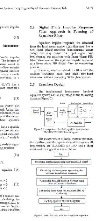
2.4
Digital Finite
Impulse
Response
Filter
Approach
in
Forming
of
Equalizer
Filter
Equalizer impulse
responsewe
obtainedfrom
the least mean square algorithmmay
has anon
linear
phasei response (non-constant groupdelay)
that may
distort
the
input.
signal.
W*e implementedthe
equalizerwith
linear phase FIR hlter. We converted the equalizer impulse responseto a
linear phaseFIR digital filter by
windowingprocess.
.
Hamming window related to afilter with
thesmallest transition
band
and high
stop-band attenuation without producing Gibbs phenomenon.2.5
Equalizer
Design
The
implemented loudspeaker far-field
equalizer system can be expressed at thefollowing
diagram (Figure 2).
The measurement of
initial
system response, the equalizer, and the equalizationofthe
systemall
implementedon
TMS320C6713 DSP anda
short [image:3.595.193.512.20.750.2]version of the algorithm was as follow.
Figure 3. TMS320C67l 3 DSP equalizer short algorithm
:. I
i
:;
a: i.. t'
(12)
tmtuk
ot>
0zmtuku=e
(15)tmfuk
a;<
0(zc(i"D,
=l
c(1d
,to
Figure 2. Loudspeaker's far-field equalizer system using TMS320C67l3 DSP block diagram.
Measuring system impulse respoose using MLS signal
Calculating minimum-phase system inpulse response using Hilbert transfomr
Calculating equalizer impulsc response using
least mean squarc algorithm
Calculating linear pliase FIR equalizer filter by rr,indos'i:rg
i.
.
The suggested SA.i valueof MLS
signalsto
the noise
is
30-50
dB
t6l.
SnV*ui*,
'.un
U.increased
by
repeating
and
u".ruf"g
the measurement
[7].
SN
value has a3
dBlrr.i._"nt
for
every double timed increm.ntof
*ur,]r.*.rrt
amount [7]..
Background noise level at the measurementis
approximatety
50 dB,
uuAio---uirrfrin"r,,
amplification has been set so theMLS
sienat level
which is
receivedat
themicropho".-*u-r8O
dB.
Therefore
ten
amountof
repeated unO-lu-"rug.ameasurement
fulfills
the MLS signal SA.{standard. The length of
MLS
sipai
must be tho samey!
or
longer than
.oo-i,
reverberation time(RT(60)
to
avoid
time_aliasingut
tfre
niisur"a
room's impulse response. The rJom,s
,"u"rioution
time at the measurement is0,gl
,,
ro rh"
t-""n-rthof
shift register that is used to generare tf,"
fraiS'lignuf
11.1!
bir
It
producesMLS
Jignal*iifrlfr"
f.lre,n
"f
2'o
bir
=
65536bit.
U^sing"44ti}
kH;,"_to,,r,
frequency,
the
MLS
-signat,s
d;#
is
(65536/44100)
s
=
1,486,
JnOti-"_ufi^irg
rviff not occur at the measurement result.,
The DSp
generated_MLS
signal
spectrumcan be seen at the following figure.
vl-/L
etoreribd
,=I*O-x++100
(16)
lhe
6"' lntematronal Conf'erence on.r; Information
&
Communication Techaologyand Systems
the measwement
is l,g
m, therefore the value of Zis 234 samples.
After
minimum_phase
system
impulse responsewas found
by
using
HitUert transiorm, equalizer impulse response was approximated using least mean square argorithm
",
;;;;;;
Jquutioo (12).With the
65536- samples lengthof
systemimpulse response, the length
of
"quifir".'impulse
response
is
determined
by
ln"
following consideration.
To
eoualizetn" t.qu"o"y^i.rpoor"
down
to
the low friquency 20 Hz,
the lengthof
equalizer's impulse
responseis
i/20
s,- whichcorresponded to
(l/20) x
44100=
2205 rurnol"r..
'
Ihe
lengthof
Hammingwindow
*ti"l
i,
used at the linear phase FIR nf
6,
upproucn'ii
zzOS samples as well.3
RESULT
.
Measurement and equalizationtest was done
in
a
room
with
the size
of
ZS
;r-'""i'
;,Sf ,
reverberation time. The positionof
tourf.*1,
unAhstener
went
to
the Gotdencri"ii,i{"{^ra,
tn"
distance between loudspeaker ana hstener was f ,S m, and the background noise jevel*u,
SOOg.-^""
,,I|"^r^ttem
frequency response measured by
t.,lrr
was comparedwith
the measurementof
the same system using a white noiseby pC
software. .The
standard deviation
of
system fr.qu"nry
response
before and after
the
equatizatioi- was
calculated.
|
""-:',0,
3.1
Yhi"l
Z
is
signal delay
at
the
cross_conelationcalculation (sample) and
x
is
tne aistance-U-#""n
loudspeaker and microphone (m). The distance
x
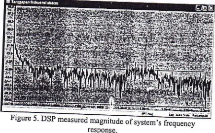
atlVstem'.s Frequency
Response
[image:4.595.34.247.387.522.2] [image:4.595.270.488.569.704.2]Evaluation
Figure
5
below
showsthe
magnitudeof
.lllr.*,1_fr:quency
response measured Uy thenSf
yrnq
MLS
signal, plotted
by
Code'Co_oor.,
Studio ofTMS320C6il3.
To
evaluatethe validity
of
that
frequency response, another frequency responseof
the sameFigure 4. TMS320C67l 3 DSp generaret MLS
signal spectrum.
.
.
.
MLS
signal has almost the same spectrum*illi*it^l'"euls
signal which hasth;
f; ,i..*_
at 20-20-000 Hz frequency
range.
.!System's impulse response was obtained by
cross-correlation between the input
MLS
signal and
received signal at the listener p-osition.
Tirie
delaybetween those
two
signals ^which-'*"ii"j
,rr" distance berweenloudSeaker
u;- _;;;;;.n",
express in samples are:
Loudspeaker's Far-field Equalization System Using Digital Signal Processor-Erisman K.L.
i
-/
system measured
using
a
white'
software.
VI-73
equalizer designed and implemented
on
DSP hasimproved the magnitude
of
frequency response inaudio frequency range of20
-
20000 Hz.Standard
deviation
of
system
frequency response magnitude before the equalization is 6,19dB, and the one after the equalization
is
*3,37 dB.By
considering-both
of
the
standard deviation values,it
was
concludedthat the
designed DSP equalizer has done itsjob.4
CONCLUSION
AND
DISCUSSION
Equalizerfilter
designedby
TMS320C67L3 can .decreasethe
standarddeviation
of
systemfrequency response magnitude
from
+6,19dB
to*3,37 dB in
audio frequency rangeof
20-
20000 Hz.The
successfulwork
of
equalizer filter
shows
the
Hilbert
transform approach
using analytic signal properties works as well.REFERENCES
tll
Hall,
Donald
E.
(1987) Basic
Acoustics. Canada : John Wiley&
Sound, lnc.l2l
Suwamo, Budhiantho
and
Setiaji
(2007) PenyamaanMedan
Dekat
Penyuara untukSatu
Pendengar
di
Satu
Posisi
Tetap.Electronics
and
Computer
EngineeringFaculty, Satyp Wacana Christian University.
t3l
B. Kapralos,M.
R.M.
Jenkin, and E.Millios
(2003) Auditory Perception and Spatial (3D)Auditory
Systems. Technical
ReportDepartment
of
Computer Science
York Universiry.M. H.
Frank andA. G. Arthur
(1985) LeastSquare Estimation
with
Applications
toDigital Signal
Processing.
AWiley-lnterscience publicatitln.
A. V.
Oppenheim andR. W.
Schafer (1989)Discrete-Time Signal
Processing. PrenticeHall Signal Processing Series.
Griesinger,
David.
Impulse
Response Measurements Using All-Pass Deconvolution. Lexicon Inc., Massachusetts, USA.Soren
Krarup
Olesen,Jan
Plogsties, Pauli Minnaar, Flemming Christensen, and HenrikMsller
(2000)
An
Improved
MLS Measurement Systemfor
Acquiring
Room Impulse Responses. Department of Acoustics,noise
by
PC".,,fri*fl,l,tt',-ft'fild
l
"'ii
G
I I
l l
g
[image:5.595.46.264.61.266.2] [image:5.595.46.255.500.640.2]rta
Figure 6. PC software measured magnitude of system's frequency response using a u'hite noise.
By
comparing figure5
and figure 6,it
hasshown
that
besidethe
magnitude valuesat
the frequencies around 20Hz
and 20000 Hz, the other magnitude valueswhich
is
measwedby DSP
issimilar
with
the one whichis
measuredby a
PC software.3.2
Equalizer
System
Evaluation
To
evaluate the equalizer, system frequency responseis
measuredby PC
software before andafter the DSP which
takesrole as an
equalizer inserted at the system.Figure
7
below
showsthe
magnitudeof
system frequency response using PC software with
a white noise after the equalization.
Figure 7. Magnitude ofsystem's frequency response
before and after the equalization.
By
comparing both of the magnitudes at thefigure 6 and figure 7,
it
has clearly shown that theg
"'i
t -.,I i *or
I I
i
L4l
t5l
t6l
L7l