PLANNING AND MANAGEMENT OF REAL-TIME GEOSPATIAL
UAS MISSIONS WITHIN A VIRTUAL GLOBE ENVIRONMENT
Stephan Nebiker, Hannes Eugster, Kevin Flückiger, Martin Christen
FHNW, University of Applied Sciences Northwestern Switzerland, Institute of Geomatics Engineering IVGI, CH-4132 Muttenz, Switzerland –
(stephan.nebiker, hannes.eugster, kevin.flueckiger, martin.christen)@fhnw.ch
Commission I, WG I/V
KEY WORDS: UAV, UAS, virtual globe, geovisualization, augmented reality, virtual reality, rapid mapping
ABSTRACT:
This paper presents the design and development of a hardware and software framework supporting all phases of typical monitoring and mapping missions with mini and micro UAVs (unmanned aerial vehicles). The developed solution combines state-of-the art collaborative virtual globe technologies with advanced geospatial imaging techniques and wireless data link technologies supporting the combined and highly reliable transmission of digital video, high-resolution still imagery and mission control data over extended operational ranges. The framework enables the planning, simulation, control and real-time monitoring of UAS missions in application areas such as monitoring of forest fires, agronomical research, border patrol or pipeline inspection. The geospatial components of the project are based on the Virtual Globe Technology i3D OpenWebGlobe of the Institute of Geomatics Engineering at the University of Applied Sciences Northwestern Switzerland (FHNW). i3D OpenWebGlobe is a high-performance 3D geovisualisation engine supporting the web-based streaming of very large amounts of terrain and POI data.
1. INTRODUCTION
Over the last few years we have witnessed major advancements in the areas of UAV airframes and propulsion, autonomous UAV control as well as geospatial imaging sensors for UAV missions. While these advancements are fundamental for UAV-based geospatial imaging missions, further components are required if complex real-time monitoring and mapping missions with multi-sensor payloads are to be supported. Typical UAV missions requiring such multi-sensor payloads include forest fire monitoring, agricultural crop monitoring or rapid mapping missions during or after natural disasters.
This paper introduces a hardware and software architecture developed as part of the UAVision research project and supporting the following phases of typical geospatial UAV missions: mission planning and simulation, mission control with augmented and virtual monitoring capabilities. The geospatial components of the project are based on the Virtual Globe Technology i3D OpenWebGlobe (Christen and Nebiker, 2010) of the Institute of Geomatics Engineering at the University of Applied Sciences Northwestern Switzerland (FHNW). i3D OpenWebGlobe is a high-performance 3D geovisualisation engine supporting the web-based streaming of very large amounts of terrain and POI data.
The paper is divided into the following sections: first, we introduce the UAVision system. The system includes the UAVision payload controller which supports multiple geospatial imaging sensors and also controls the UAVision communication layer. The UAVision communication layer consists of a light-weight high-performance digital video and imagery data link, which was developed by project partners at EPFL Lausanne. In the following section, the aspects of real-time video georegistration and integration as well as the video
based 3d mapping functionality will be discussed. The captured video data is georeferenced in real-time – either by direct georeferencing using the flight control data of the UAV platform or alternatively by an integrated georeferencing approach (Eugster, submitted). The georeferenced video streams can then be exploited directly within the Virtual Globe in either an Augmented Monitoring or a Virtual Monitoring scenario. In the subsequent section a number of real-world applications and experiences with the UAVision system architecture are presented. Finally, we provide some conclusions and an outlook on future developments.
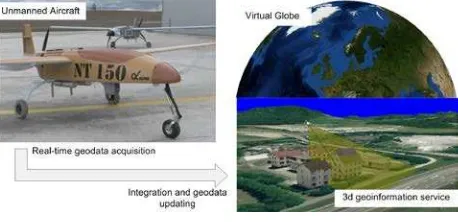
Figure 1: Goal of the UAVision project: integration of UAV mission management and UAV based geodata into a virtual globe environment. UAV NT150 (left) – i3D OpenWebGlobe
(right)
2. UAVISION SYSTEM OVERVIEW
The term Unmanned Aircraft System (UAS) has been introduced for describing system solutions enabling the operation of one or more Unmanned Aerial Vehicles (UAV) (Weatherington, 2005). A UAS typically consists of a UAV with a navigation control unit and with additional International Archives of the Photogrammetry, Remote Sensing and Spatial Information Sciences, Volume XXXVIII-1/C22, 2011
environmental sensors, e.g. for the capturing of geodata. Additionally, a UAS comprises a ground control station plus wireless data link components. The terms mini and micro UAV are used for platforms with a maximum take-off weight of 30 kg or 5 kg respectively. A summary of current civilian platforms and a more detailed categorisation can be found in Bento (2008).
The UAVision project and the resulting UAVision system architecture and its components were designed to turn a mini or micro UAV into a full UAS solution supporting geospatial real-time monitoring and mapping missions with a strong focus on real-time georegistration and real-time exploitation in a virtual globe environment. In the following section, we first introduce the system architecture and its hardware components. Subsequently, we focus on the software solution which supports the entire process chain – from mission planning and simulation, followed by mission monitoring right through to the integration and exploitation of the captured geodata within a virtual globe.
2.1 System Architecture
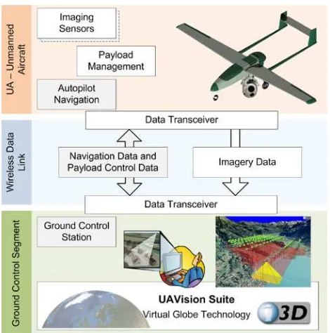
The UAVision system solution covers the three segments: UAV platform segment, data communication segment and ground control segment (Figure 2). The UAVision architecture supports different UAV platforms which can be equipped with application specific (geo) sensors such as video or still image cameras etc. Prerequisite is an integrated navigation or flight attitude control unit (autopilot) which supports an autonomous or user-controlled navigation and the transmission of user data (e.g. control commands for external sensors on the UAV). In principle, different navigation control units could be used in conjunction with the UAVision system. Currently, we support an autopilot by UAVNavigation (www.uavnavigation.com) in combination with the ground control station and the integrated navigation data link by the same provider.
Figure 2: UAVision system architecture and hardware components
2.2 UAVision Payload Management System
UAVision complements this 'standard' UAS architecture by an additional, largely 'orthogonal' payload management system. The UAVision payload management system controls the payload sensors, the onboard storage as well as the dedicated payload data link components.
The UAVision payload controller consists of off-the-shelf computer hardware integrated onto a custom built PC-104 mainboard. The system is mounted into an aluminium casing to allow for fanless operation of the controller even in high temperature environments. The controller is running Windows XP with the UAVision payload controller software to manage the different on-board devices. Since power supply on board is a major challenge on smaller UAV platforms, the components chosen are all optimized for power efficiency. The following main components have been integrated into our controller:
• Intel Atom Z530 1.6 GHz CPU • 1024 MB DDR 2 RAM • 40 GB SSD Disk
Figure 3: UAVision payload controller in custom casing with the different interconnects
2.3 UAVision Communication Layer
The communication layer is responsible for the transmission of navigation data and flight control commands as well as for the transmission of the captured geodata from the UAV to the ground control station. In the UAVision environment, this is achieved with two different wireless data links. The navigation data and the control commands are transmitted through the 'standard' bidirectional data link provided by the UAS manufacturer. These standard data links are primarily designed for reliability and not for the highly efficient transmission of bulk data. Therefore, a dedicated unidirectional data link for the highly efficient transmission of large volumes of imagery data from multiple sensors was developed as part of the UAVision project. Currently, the simultaneous transmission of a PAL and a CameraLink channel are supported. One of the features of the new data link components is the support for an ultra-low-delay video compression with an end-to-end delay of less than 40 ms. This ultra-low delay video link is an important component, for example, for remotely piloting UAVs in a virtual cockpit International Archives of the Photogrammetry, Remote Sensing and Spatial Information Sciences, Volume XXXVIII-1/C22, 2011
without causing motion sickness. The virtual cockpit furthermore allows the augmentation of elements such as air traffic control data or flight obstacles into the cockpit display, which could dramatically improve the safe operation of UAVs. However, an operational implementation again requires a maximum delay of the transmitted video data of 1-2 frames.
2.4 UAVision Ground Control Station
The UAVision ground control station consists of the 'standard' ground control unit of the UAS which is complemented by a second PC running the UAVision software for planning and monitoring the geospatial monitoring mission. The functionality of the UAVision mission management software is described in more detail in the following section.
2.5 UAVision Mission Management Software
The implemented UAVision software solution consists of four different modules supporting geospatial monitoring and mapping missions from A-Z. This includes various process steps from mission planning and simulation, the actual mission control right through to the steps of real-time or offline monitoring directly within 3d geoinformation services. Figure 4 shows the process chain with the corresponding UAVision mission management modules which are all based on the i3D OpenWebGlobe virtual globe technology.
Figure 4: UAVision software modules for UAV based geospatial data acquisition missions
2.5.1 Mission Planning & Simulation
Geospatial UAS missions can either directly be planned within the virtual globe or imported from other programs, e.g. from Topoflight 3D Flight Planning Software (Flotron AG, 2011). The UAVision flight plans contain flight lines, navigation waypoints as well as events for controlling the payload sensors. With this functionality, sophisticated missions with complex flight patterns, multi-sensor constellations with changing acquisition parameters, or range dependent transmissions parameters can be planned and executed. A traditional aerial photogrammetric survey with predefined exposure points could be considered a special case of such a generic mission.
2.5.2 Mission Control
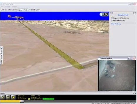
Once a mission has been planned, it can be carried out and monitored fully automatically. The current mission state including platform position and orientation as well as the view frustums of the imaging sensors are displayed in the virtual globe (see Figure 6). At the same time important system status information is constantly updated and displayed in a second window. The automatic mission mode can very quickly be overridden by the operator or by mission updates. For example, due to memory limitations on the autopilot used, the mission control module regularly uploads subsequent pieces of the flight plan with the next sequence of waypoints and sensor events. The commands for the sensor and data link payload commands are received and processed by the UAVision payload management system directly on the UAV. All imagery and navigation data received over the navigation and the payload data links can be recorded by the mission control software for later offline processing and analysis.
2.5.3 Virtual and Augmented Monitoring
This UAVision module supports two mixed reality scenarios integrating the captured video streams of the real-world with the virtual environment of the virtual globe. This integration builds upon the implemented video georeferencing functionality which will be discussed in section 3. In a first scenario, subsequently referred to as Augmented Monitoring, the georeferenced video stream is augmented with objects from the virtual globe (see Figure 5). In the second scenario, referred to as Virtual Monitoring, the UAV platform and the view frustums of the video sensors are displayed in the virtual globe while the video is shown in a separate window (Figure 6). Additional functionality allows the digitising and annotating of objects or events in the georeferenced video.
2.5.4 Rapid Mapping
Goal of the Rapid Mapping module is the integration of UAV based imagery into the virtual globe's base map in (near) real-time. This will enable the continuous updating of the geospatial base data, which is accessed by 2d and 3d geoinformation services. Such a rapid updating of the underlying base map will dramatically improve the decision making process in disaster management or in the assessment of dynamic environmental processes.
3. VIDEO GEOREFERENCING AND INTEGRATION
The Augmented and Virtual Monitoring modules presented above require the real-time georeferencing of the captured video stream(s), on the one hand, and the integration of this imagery into a virtual globe environment, on the other hand. The implemented solution is based on the direct georeferencing approach (Mostafa and Hutton, 2005).
In our solution, we directly use the flight state provided by the flight controller, i.e. the autopilot of the UAV platform. The flight state consists of the platform position and attitude with respect to a geodetic reference system (e.g. WGS 84) and the time epoch in a UTC time reference. This data is transmitted from the UAV to the ground control station in real-time – in parallel to the video data. The subsequent georeferencing process requires the correct synchronisation of the video data with the flight state data. For this purpose UTC time stamp International Archives of the Photogrammetry, Remote Sensing and Spatial Information Sciences, Volume XXXVIII-1/C22, 2011
information is encoded into the video. The georeferencing of the video and its subsequent integration into the 3d virtual globe are performed by a geospatial video processing component. This component is based on a filter graph concept in which each frame of the video sequence is sequentially processed. In a first filter, the time stamp information for each frame is extracted. In a second filter, the exterior orientation parameters for each available flight state are determined after applying the calibration parameters (lever arm and misalignment) (Skaloud, 1999). Additionally, the exterior orientation of each frame is determined based on its time stamp information – either by interpolation or prediction. In the case of offline processing, the solution is always interpolated. However, in the real-time case a prediction of the solution is required due to the lower frequency of the navigation updates and the delay in transmitting them to the ground control station. The last filter provides the calculated exterior orientation together with the interior orientation of the respective sensor to the render engine of the i3D OpenWebGlobe. Based on this information, the UAVision software can now augment the georeferenced video imagery with additional geospatial contents provided by the virtual globe. An in-depth discussion of the direct video georeferencing solution but also of the more recent integrated georeferencing approach using existing 3d geometry (e.g. city models) can be found in Eugster & Nebiker (2008) and Eugster (submitted).
The Augmented & Virtual Monitoring module also provides a basic mapping functionality for digitising geospatial objects. The function permits the interactive digitising of arbitrary point, line and polygon features directly within the georeferenced video sequence. The 3d point determination is based on a 3d monoplotting approach intersecting the image ray with the currently loaded elevation model of the virtual globe (Kraus and Waldhäusl, 1997, Chapt. 6.5.3). The captured geospatial objects are organised in layers and can easily be integrated with existing GIS solutions.
Figure 5: Augmented Monitoring with integrated mapping functionality
4. FIRST EXPERIMENTS AND APPLICATIONS
The UAVision prototype system was tested in a number of test flight campaigns in Amman (Jordan), Marugan (Spain) and Eiken (Switzerland). In these test campaigns the implemented UAVision software and hardware components could be successfully validated. In these flight tests a number of
applications were simulated and flight tested. These applications included the inspection and surveillance of infrastructure objects (e.g. pipelines), the detection and monitoring of forest fires, and search and rescue operations.
Figure 6: Virtual Monitoring – video integration scenario
The integrated mapping functionality proved very helpful in rapidly extracting object coordinates, e.g. as target information for fire fighters, in rapidly determining the extents of a problem, e.g. a bush fire, or in being able to accurately revisit earlier positions, e.g. fire hotspots. The possibility of augmenting existing geospatial data (e.g. 3d city models) such as shown in Figure 5 proved to be a very valuable tool for efficient change detection and monitoring.
5. CONCLUSIONS AND OUTLOOK
In this paper we introduced the UAVision system, a combined hardware and software solution supporting professional UAV based real-time monitoring and mapping missions directly integrated within a web-based virtual globe technology.
The UAVision system can be combined with different UAV platforms and different geosensors, depending on the requirements of the specific application to be addressed. As originally intended, the implemented UAVision software is suitable to cover the entire process chain of geospatial UAV missions, from mission planning and mission execution to mission monitoring and analysis. The UAVision payload management system, which was only introduced later in the project, proved very valuable in supporting and controlling different and interchangeable combinations of sensors and data link components on small UAVs.
Our current research focus is on the development of an open source next generation virtual globe. The project is called OpenWebGlobe (Christen and Nebiker, 2011; FHNW University of Applied Sciences Northwestern Switzerland, 2011) and it encompasses the viewer and the processing functionality. It features a completely new multi-language architecture and has also just been released as a plugin-free web version for WebGL and HTML5. The OpenWebGlobe architecture will incorporate many of the features identified in the UAVision project, namely real-time support, rapid updating of geospatial contents and, for example, a streaming support for very large 3d point clouds, which might well be acquired and updated by future UAVs.
6. ACKNOWLEDGEMENTS
The UAVision research project was co-funded by the Swiss Commission for Technology and Innovation CTI and was carried out in cooperation with our academic partners at the GR-LSM Multimedia Group of EPF Lausanne, who were responsible for the data link components.
7. REFERENCES
Bento, M., 2008. Unmanned Aerial Vehicles: An Overview, InsideGNSS, pp. 54-61.
Christen, M. and Nebiker, S., 2010. Neue Entwicklungen im Bereich Virtueller Globen am Beispiel der i3D-Technologie, DGPF Tagungsband 19/2010 – Dreiländertagung OVG, DGPF und SGPF, Wien.
Christen, M. and Nebiker, S., 2011. OpenWebGlobe SDK - An Open Source High-Performance Virtual Globe SDK for Open Maps, 1st European State of the Map Conference, Vienna. Eugster, H., submitted. Echtzeit-Georegistrierung von Videodaten mit Hilfe von Navigationssensoren geringer Qualität und digitalen 3D-Landschaftsmodellen. PhD Dissertation Thesis, Humboldt-Universität zu Berlin, Berlin. Eugster, H. and Nebiker, S., 2008. UAV-Based Augmented Monitoring - Real-Time Georeferencing and Integration of Video Imagery with Virtual Globes, XXI ISPRS Congress. International Archives of Photogrammetry, Remote Sensing and Spatial Information Sciences, Beijing.
FHNW University of Applied Sciences Northwestern Switzer-land, 2011. OpenWebGlobe SDK, www.openwebglobe.org. Flotron AG, 2011. Topoflight - 3D Flight Planning Software. Kraus, K. and Waldhäusl, P., 1997. Grundlagen und Standardverfahren. Dümmler, Bonn, 394 pp.
Mostafa, M. and Hutton, J., 2005. 10 Years of Direct Georeferencing for Airborne Photogrammetry, GIS.
Skaloud, J., 1999. Problems in Direct-Georeferencing by INS/DGPS in the Airborne Environmant, ISPRS Workshop 'Direct versus Indirect Methods of Sensor Orientation', Barcelona.
Weatherington, D., 2005. Unmanned Aircraft Systems (UAS) Roadmap 2005-2030 (3rd Edition) In: U.D.o.D. (DoD) (Editor).