SECOND EDITION
Arduino Cookbook
Michael Margolis
Arduino Cookbook, Second Edition by Michael Margolis
Copyright © 2012 Michael Margolis, Nicholas Weldin. All rights reserved. Printed in the United States of America.
Published by O’Reilly Media, Inc., 1005 Gravenstein Highway North, Sebastopol, CA 95472.
O’Reilly books may be purchased for educational, business, or sales promotional use. Online editions are also available for most titles (http://my.safaribooksonline.com). For more information, contact our corporate/institutional sales department: (800) 998-9938 or [email protected].
Editors: Shawn Wallace and Brian Jepson Production Editor: Teresa Elsey
Proofreader: Kiel Van Horn
Indexer: Lucie Haskins
Cover Designer: Karen Montgomery Interior Designer: David Futato Illustrator: Robert Romano
March 2011: First Edition. December 2011: Second Edition.
Revision History for the Second Edition: 2011-12-09 First release
See http://oreilly.com/catalog/errata.csp?isbn=9781449313876 for release details.
Nutshell Handbook, the Nutshell Handbook logo, and the O’Reilly logo are registered trademarks of O’Reilly Media, Inc. Arduino Cookbook, the image of a toy rabbit, and related trade dress are trademarks of O’Reilly Media, Inc.
Many of the designations used by manufacturers and sellers to distinguish their products are claimed as trademarks. Where those designations appear in this book, and O’Reilly Media, Inc., was aware of a trademark claim, the designations have been printed in caps or initial caps.
While every precaution has been taken in the preparation of this book, the publisher and authors assume no responsibility for errors or omissions, or for damages resulting from the use of the information con-tained herein.
Table of Contents
Preface . . . xi
1. Getting Started . . . 1
1.1 Installing the Integrated Development Environment (IDE) 4
1.2 Setting Up the Arduino Board 8
1.3 Using the Integrated Development Environment (IDE) to Prepare
an Arduino Sketch 10
1.4 Uploading and Running the Blink Sketch 13
1.5 Creating and Saving a Sketch 14
1.6 Using Arduino 17
2. Making the Sketch Do Your Bidding . . . 23
2.1 Structuring an Arduino Program 24
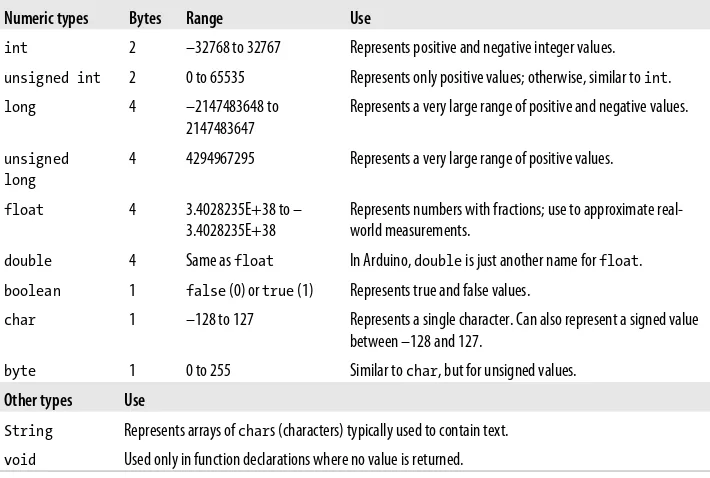
2.2 Using Simple Primitive Types (Variables) 25
2.3 Using Floating-Point Numbers 27
2.4 Working with Groups of Values 29
2.5 Using Arduino String Functionality 32
2.6 Using C Character Strings 37
2.7 Splitting Comma-Separated Text into Groups 38
2.8 Converting a Number to a String 41
2.9 Converting a String to a Number 43
2.10 Structuring Your Code into Functional Blocks 45
2.11 Returning More Than One Value from a Function 49
2.12 Taking Actions Based on Conditions 52
2.13 Repeating a Sequence of Statements 53
2.14 Repeating Statements with a Counter 55
2.15 Breaking Out of Loops 58
2.16 Taking a Variety of Actions Based on a Single Variable 59
2.17 Comparing Character and Numeric Values 61
2.18 Comparing Strings 63
2.19 Performing Logical Comparisons 64
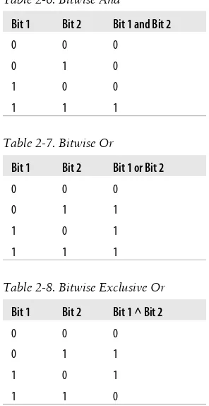
2.20 Performing Bitwise Operations 65
2.21 Combining Operations and Assignment 68
3. Using Mathematical Operators . . . 69
3.1 Adding, Subtracting, Multiplying, and Dividing 69
3.2 Incrementing and Decrementing Values 70
3.3 Finding the Remainder After Dividing Two Values 71
3.4 Determining the Absolute Value 72
3.5 Constraining a Number to a Range of Values 73
3.6 Finding the Minimum or Maximum of Some Values 74
3.7 Raising a Number to a Power 75
3.8 Taking the Square Root 76
3.9 Rounding Floating-Point Numbers Up and Down 76
3.10 Using Trigonometric Functions 77
3.11 Generating Random Numbers 78
3.12 Setting and Reading Bits 80
3.13 Shifting Bits 84
3.14 Extracting High and Low Bytes in an int or long 85
3.15 Forming an int or long from High and Low Bytes 87
4. Serial Communications . . . 89
4.1 Sending Debug Information from Arduino to Your Computer 94
4.2 Sending Formatted Text and Numeric Data from Arduino 97
4.3 Receiving Serial Data in Arduino 100
4.4 Sending Multiple Text Fields from Arduino in a Single Message 105
4.5 Receiving Multiple Text Fields in a Single Message in Arduino 111
4.6 Sending Binary Data from Arduino 114
4.7 Receiving Binary Data from Arduino on a Computer 118
4.8 Sending Binary Values from Processing to Arduino 120
4.9 Sending the Value of Multiple Arduino Pins 122
4.10 How to Move the Mouse Cursor on a PC or Mac 125
4.11 Controlling Google Earth Using Arduino 130
4.12 Logging Arduino Data to a File on Your Computer 135
4.13 Sending Data to Two Serial Devices at the Same Time 138
4.14 Receiving Serial Data from Two Devices at the Same Time 141
4.15 Setting Up Processing on Your Computer to Send
and Receive Serial Data 145
5. Simple Digital and Analog Input . . . 147
5.1 Using a Switch 150
5.2 Using a Switch Without External Resistors 154
5.3 Reliably Detecting the Closing of a Switch 155
5.5 Reading a Keypad 163
5.6 Reading Analog Values 166
5.7 Changing the Range of Values 168
5.8 Reading More Than Six Analog Inputs 170
5.9 Displaying Voltages Up to 5V 173
5.10 Responding to Changes in Voltage 176
5.11 Measuring Voltages More Than 5V (Voltage Dividers) 177
6. Getting Input from Sensors . . . 181
6.1 Detecting Movement 183
6.2 Detecting Light 186
6.3 Detecting Motion (Integrating Passive Infrared Detectors) 187
6.4 Measuring Distance 189
6.5 Measuring Distance Accurately 193
6.6 Detecting Vibration 197
6.7 Detecting Sound 198
6.8 Measuring Temperature 202
6.9 Reading RFID Tags 206
6.10 Tracking Rotary Movement 208
6.11 Tracking the Movement of More Than One Rotary Encoder 211
6.12 Tracking Rotary Movement in a Busy Sketch 214
6.13 Using a Mouse 216
6.14 Getting Location from a GPS 220
6.15 Detecting Rotation Using a Gyroscope 225
6.16 Detecting Direction 230
6.17 Getting Input from a Game Control Pad (PlayStation) 235
6.18 Reading Acceleration 237
7. Visual Output . . . 241
7.1 Connecting and Using LEDs 245
7.2 Adjusting the Brightness of an LED 248
7.3 Driving High-Power LEDs 249
7.4 Adjusting the Color of an LED 252
7.5 Sequencing Multiple LEDs: Creating a Bar Graph 255
7.6 Sequencing Multiple LEDs: Making a Chase Sequence (Knight
Rider) 258
7.7 Controlling an LED Matrix Using Multiplexing 259
7.8 Displaying Images on an LED Matrix 262
7.9 Controlling a Matrix of LEDs: Charlieplexing 265
7.10 Driving a 7-Segment LED Display 271
7.11 Driving Multidigit, 7-Segment LED Displays: Multiplexing 274
7.12 Driving Multidigit, 7-Segment LED Displays Using MAX7221 Shift
Registers 276
7.13 Controlling an Array of LEDs by Using MAX72xx Shift Registers 279 7.14 Increasing the Number of Analog Outputs Using PWM Extender
Chips (TLC5940) 281
7.15 Using an Analog Panel Meter as a Display 285
8. Physical Output . . . 289
8.1 Controlling the Position of a Servo 292
8.2 Controlling One or Two Servos with a Potentiometer or Sensor 294
8.3 Controlling the Speed of Continuous Rotation Servos 296
8.4 Controlling Servos Using Computer Commands 298
8.5 Driving a Brushless Motor (Using a Hobby Speed Controller) 299
8.6 Controlling Solenoids and Relays 300
8.7 Making an Object Vibrate 302
8.8 Driving a Brushed Motor Using a Transistor 304
8.9 Controlling the Direction of a Brushed Motor with an H-Bridge 306
8.10 Controlling the Direction and Speed of a Brushed Motor with an
H-Bridge 309
8.11 Using Sensors to Control the Direction and Speed of Brushed
Motors (L293 H-Bridge) 311
8.12 Driving a Bipolar Stepper Motor 317
8.13 Driving a Bipolar Stepper Motor (Using the EasyDriver Board) 320
8.14 Driving a Unipolar Stepper Motor (ULN2003A) 323
9. Audio Output . . . 327
9.1 Playing Tones 329
9.2 Playing a Simple Melody 331
9.3 Generating More Than One Simultaneous Tone 333
9.4 Generating Audio Tones and Fading an LED 335
9.5 Playing a WAV File 338
9.6 Controlling MIDI 341
9.7 Making an Audio Synthesizer 344
10. Remotely Controlling External Devices . . . 347
10.1 Responding to an Infrared Remote Control 348
10.2 Decoding Infrared Remote Control Signals 350
10.3 Imitating Remote Control Signals 354
10.4 Controlling a Digital Camera 357
10.5 Controlling AC Devices by Hacking a Remote-Controlled Switch 359
11. Using Displays . . . 363
11.1 Connecting and Using a Text LCD Display 364
11.2 Formatting Text 367
11.4 Scrolling Text 372
11.5 Displaying Special Symbols 375
11.6 Creating Custom Characters 377
11.7 Displaying Symbols Larger Than a Single Character 379
11.8 Displaying Pixels Smaller Than a Single Character 382
11.9 Connecting and Using a Graphical LCD Display 385
11.10 Creating Bitmaps for Use with a Graphical Display 389
11.11 Displaying Text on a TV 391
12. Using Time and Dates . . . 397
12.1 Creating Delays 397
12.2 Using millis to Determine Duration 398
12.3 More Precisely Measuring the Duration of a Pulse 402
12.4 Using Arduino as a Clock 404
12.5 Creating an Alarm to Periodically Call a Function 412
12.6 Using a Real-Time Clock 415
13. Communicating Using I2C and SPI . . . 421
13.1 Controlling an RGB LED Using the BlinkM Module 425
13.2 Using the Wii Nunchuck Accelerometer 430
13.3 Interfacing to an External Real-Time Clock 435
13.4 Adding External EEPROM Memory 437
13.5 Reading Temperature with a Digital Thermometer 441
13.6 Driving Four 7-Segment LEDs Using Only Two Wires 445
13.7 Integrating an I2C Port Expander 449
13.8 Driving Multidigit, 7-Segment Displays Using SPI 451
13.9 Communicating Between Two or More Arduino Boards 454
14. Wireless Communication . . . 459
14.1 Sending Messages Using Low-Cost Wireless Modules 459
14.2 Connecting Arduino to a ZigBee or 802.15.4 Network 465
14.3 Sending a Message to a Particular XBee 472
14.4 Sending Sensor Data Between XBees 475
14.5 Activating an Actuator Connected to an XBee 480
14.6 Sending Messages Using Low-Cost Transceivers 486
14.7 Communicating with Bluetooth Devices 491
15. Ethernet and Networking . . . 495
15.1 Setting Up the Ethernet Shield 498
15.2 Obtaining Your IP Address Automatically 500
15.3 Resolving Hostnames to IP Addresses (DNS) 502
15.4 Requesting Data from a Web Server 504
15.5 Requesting Data from a Web Server Using XML 508
15.6 Setting Up an Arduino to Be a Web Server 511
15.7 Handling Incoming Web Requests 514
15.8 Handling Incoming Requests for Specific Pages 517
15.9 Using HTML to Format Web Server Responses 521
15.10 Serving Web Pages Using Forms (POST) 525
15.11 Serving Web Pages Containing Large Amounts of Data 528
15.12 Sending Twitter Messages 535
15.13 Sending and Receiving Simple Messages (UDP) 539
15.14 Getting the Time from an Internet Time Server 545
15.15 Monitoring Pachube Feeds 550
15.16 Sending Information to Pachube 556
16. Using, Modifying, and Creating Libraries . . . 561
16.1 Using the Built-in Libraries 561
16.2 Installing Third-Party Libraries 563
16.3 Modifying a Library 565
16.4 Creating Your Own Library 568
16.5 Creating a Library That Uses Other Libraries 574
16.6 Updating Third-Party Libraries for Arduino 1.0 580
17. Advanced Coding and Memory Handling . . . 583
17.1 Understanding the Arduino Build Process 584
17.2 Determining the Amount of Free and Used RAM 587
17.3 Storing and Retrieving Numeric Values in Program Memory 589
17.4 Storing and Retrieving Strings in Program Memory 592
17.5 Using #define and const Instead of Integers 594
17.6 Using Conditional Compilations 595
18. Using the Controller Chip Hardware . . . 599
18.1 Storing Data in Permanent EEPROM Memory 603
18.2 Using Hardware Interrupts 606
18.3 Setting Timer Duration 609
18.4 Setting Timer Pulse Width and Duration 611
18.5 Creating a Pulse Generator 614
18.6 Changing a Timer’s PWM Frequency 617
18.7 Counting Pulses 620
18.8 Measuring Pulses More Accurately 621
18.9 Measuring Analog Values Quickly 624
18.10 Reducing Battery Drain 626
18.11 Setting Digital Pins Quickly 627
18.12 Uploading Sketches Using a Programmer 630
18.13 Replacing the Arduino Bootloader 632
A. Electronic Components . . . 637
B. Using Schematic Diagrams and Data Sheets . . . 643
C. Building and Connecting the Circuit . . . 651
D. Tips on Troubleshooting Software Problems . . . 655
E. Tips on Troubleshooting Hardware Problems . . . 659
F. Digital and Analog Pins . . . 663
G. ASCII and Extended Character Sets . . . 667
H. Migrating to Arduino 1.0 . . . 671
Index . . . 677
Preface
This book was written by Michael Margolis with Nick Weldin to help you explore the amazing things you can do with Arduino.
Arduino is a family of microcontrollers (tiny computers) and a software creation envi-ronment that makes it easy for you to create programs (called sketches) that can interact with the physical world. Things you make with Arduino can sense and respond to touch, sound, position, heat, and light. This type of technology, often referred to as
physical computing, is used in all kinds of things from the iPhone to automobile elec-tronics systems. Arduino makes it possible for anyone with an interest—even people with no programming or electronics experience—to use this rich and complex technology.
Who This Book Is For
Unlike in most technical cookbooks, experience with software and hardware is not assumed. This book is aimed at readers interested in using computer technology to interact with the environment. It is for people who want to quickly find the solution to hardware and software problems. The recipes provide the information you need to accomplish a broad range of tasks. It also has details to help you customize solutions to meet your specific needs. There is insufficient space in a book limited to 700 pages to cover general theoretical background, so links to external references are provided
throughout the book. See “What Was Left Out” on page xiv for some general
refer-ences for those with no programming or electronics experience.
If you have no programming experience—perhaps you have a great idea for an inter-active project but don’t have the skills to develop it—this book will help you learn what you need to know to write code that works, using examples that cover over 200 com-mon tasks.
If you have some programming experience but are new to Arduino, the book will help you become productive quickly by demonstrating how to implement specific Arduino capabilities for your project.
People already using Arduino should find the content helpful for quickly learning new techniques, which are explained using practical examples. This will help you to embark on more complex projects by showing how to solve problems and use capabilities that may be new to you.
Experienced C/C++ programmers will find examples of how to use the low-level AVR resources (interrupts, timers, I2C, Ethernet, etc.) to build applications using the Arduino environment.
How This Book Is Organized
The book contains information that covers the broad range of the Arduino’s capabili-ties, from basic concepts and common tasks to advanced technology. Each technique is explained in a recipe that shows you how to implement a specific capability. You do not need to read the content in sequence. Where a recipe uses a technique covered in another recipe, the content in the other recipe is referenced rather than repeating details in multiple places.
Chapter 1, Getting Started, introduces the Arduino environment and provides help on getting the Arduino development environment and hardware installed and working. The next couple of chapters introduce Arduino software development. Chapter 2,
Making the Sketch Do Your Bidding, covers essential software concepts and tasks, and
Chapter 3, Using Mathematical Operators, shows how to make use of the most common mathematical functions.
Chapter 4, Serial Communications, describes how to get Arduino to connect and com-municate with your computer and other devices. Serial is the most common method for Arduino input and output, and this capability is used in many of the recipes throughout the book.
Chapter 5, Simple Digital and Analog Input, introduces a range of basic techniques for reading digital and analog signals. Chapter 6, Getting Input from Sensors, builds on this with recipes that explain how to use devices that enable Arduino to sense touch, sound, position, heat, and light.
Chapter 7, Visual Output, covers controlling light. Recipes cover switching on one or many LEDs and controlling brightness and color. This chapter explains how you can drive bar graphs and numeric LED displays, as well as create patterns and animations with LED arrays. In addition, the chapter provides a general introduction to digital and analog output for those who are new to this.
Chapter 9, Audio Output, shows how to generate sound with Arduino through an out-put device such as a speaker. It covers playing simple tones and melodies and playing WAV files and MIDI.
Chapter 10, Remotely Controlling External Devices, describes techniques that can be used to interact with almost any device that uses some form of remote controller, in-cluding TV, audio equipment, cameras, garage doors, appliances, and toys. It builds on techniques used in previous chapters for connecting Arduino to devices and modules.
Chapter 11, Using Displays, covers interfacing text and graphical LCD displays. The chapter shows how you can connect these devices to display text, scroll or highlight words, and create special symbols and characters.
Chapter 12, Using Time and Dates, covers built-in Arduino time-related functions and introduces many additional techniques for handling time delays, time measurement, and real-world times and dates.
Chapter 13, Communicating Using I2C and SPI, covers the Inter-Integrated Circuit (I2C) and Serial Peripheral Interface (SPI) standards. These standards provide simple ways for digital information to be transferred between sensors and Arduino. This chap-ter shows how to use I2C and SPI to connect to common devices. It also shows how to connect two or more Arduino boards, using I2C for multiboard applications.
Chapter 14, Wireless Communication, covers wireless communication with XBee and other wireless modules. This chapter provides examples ranging from simple wireless serial port replacements to mesh networks connecting multiple boards to multiple sensors.
Chapter 15, Ethernet and Networking, describes the many ways you can use Arduino with the Internet. It has examples that demonstrate how to build and use web clients and servers and shows how to use the most common Internet communication protocols with Arduino.
Arduino software libraries are a standard way of adding functionality to the Arduino environment. Chapter 16, Using, Modifying, and Creating Libraries, explains how to use and modify software libraries. It also provides guidance on how to create your own libraries.
Chapter 17, Advanced Coding and Memory Handling, covers advanced programming techniques, and the topics here are more technical than the other recipes in this book because they cover things that are usually concealed by the friendly Arduino wrapper. The techniques in this chapter can be used to make a sketch more efficient—they can help improve performance and reduce the code size of your sketches.
Chapter 18, Using the Controller Chip Hardware, shows how to access and use hard-ware functions that are not fully exposed through the documented Arduino language. It covers low-level usage of the hardware input/output registers, timers, and interrupts.
Appendix A, Electronic Components, provides an overview of the components used throughout the book.
Appendix B, Using Schematic Diagrams and Data Sheets, explains how to use schematic diagrams and data sheets.
Appendix C, Building and Connecting the Circuit, provides a brief introduction to using a breadboard, connecting and using external power supplies and batteries, and using capacitors for decoupling.
Appendix D, Tips on Troubleshooting Software Problems, provides tips on fixing com-pile and runtime problems.
Appendix E, Tips on Troubleshooting Hardware Problems, covers problems with elec-tronic circuits.
Appendix F, Digital and Analog Pins, provides tables indicating functionality provided by the pins on standard Arduino boards.
Appendix G, ASCII and Extended Character Sets, provides tables showing ASCII characters.
Appendix H, Migrating to Arduino 1.0, explains how to modify code written for pre-vious releases to run correctly with Arduino 1.0.
What Was Left Out
There isn’t room in this book to cover electronics theory and practice, although guid-ance is provided for building the circuits used in the recipes. For more detail, readers may want to refer to material that is widely available on the Internet or to books such as the following:
• Make: Electronics by Charles Platt (O’Reilly; search for it on oreilly.com) • Getting Started in Electronics by Forrest M. Mims III (Master Publishing) • Physical Computing by Dan O’Sullivan and Tom Igoe (Cengage)
• Practical Electronics for Inventors by Paul Scherz (McGraw-Hill)
My favorite, although not really a beginner’s book, is the book I used to learn C programming:
• The C Programming Language by Brian W. Kernighan and Dennis M. Ritchie (Prentice Hall)
Code Style (About the Code)
The code used throughout this book has been tailored to clearly illustrate the topic covered in each recipe. As a consequence, some common coding shortcuts have been avoided, particularly in the early chapters. Experienced C programmers often use rich but terse expressions that are efficient but can be a little difficult for beginners to read. For example, the early chapters increment variables using explicit expressions that are easy for nonprogrammers to read:
result = result + 1; // increment the count
Rather than the following, commonly used by experienced programmers, that does the same thing:
result++; // increment using the post increment operator
Feel free to substitute your preferred style. Beginners should be reassured that there is no benefit in performance or code size in using the terse form.
Some programming expressions are so common that they are used in their terse form. For example, the loop expressions are written as follows:
for(int i=0; i < 4; i++)
This is equivalent to the following:
int i;
for(i=0; i < 4; i = i+1)
See Chapter 2 for more details on these and other expressions used throughout the book.
Good programming practice involves ensuring that values used are valid (garbage in equals garbage out) by checking them before using them in calculations. However, to keep the code focused on the recipe topic, very little error-checking code has been included.
Arduino Platform Release Notes
This edition has been updated for Arduino 1.0. All of the code has been tested with the latest Arduino 1.0 release candidate at the time of going to press (RC2). The download code for this edition will be updated online if necessary to support the final 1.0 release, so check the book’s website to get the latest code. The download contains a file named
changelog.txt that will indicate code that has changed from the published edition.
Although many of the sketches will run on earlier Arduino releases, you need to change the extension from .ino to .pde to load the sketch into a pre-1.0 IDE. If you have not migrated to Arduino 1.0 and have good reason to stick with an earlier release, you can use the example code from the first edition of this book (available at http://shop.oreilly .com/product/9780596802486.do), which has been tested with releases from 0018 to 0022. Note that many recipes in the second edition have been enhanced, so we en-courage you to upgrade to Arduino 1.0. If you need help migrating older code, see
Appendix H.
There’s also a link to errata on that site. Errata give readers a way to let us know about typos, errors, and other problems with the book. Errata will be visible on the page immediately, and we’ll confirm them after checking them out. O’Reilly can also fix errata in future printings of the book and on Safari, making for a better reader experi-ence pretty quickly.
If you have problems making examples work, check the changelog.txt file in the latest code download to see if the sketch has been updated. If that doesn’t fix the problem, see Appendix D, which covers troubleshooting software problems. The Arduino forum is a good place to post a question if you need more help: http://www.arduino.cc. If you like—or don’t like—this book, by all means, please let people know. Amazon reviews are one popular way to share your happiness or other comments. You can also leave reviews at the O’Reilly site for the book.
Conventions Used in This Book
The following font conventions are used in this book:
Italic
Indicates pathnames, filenames, and program names; Internet addresses, such as domain names and URLs; and new items where they are defined
Constant width
Indicates command lines and options that should be typed verbatim; names and keywords in programs, including method names, variable names, and class names; and HTML element tags
Constant width bold
Indicates emphasis in program code lines
Constant width italic
Indicates text that should be replaced with user-supplied values
This icon indicates a warning or caution.
Using Code Examples
This book is here to help you make things with Arduino. In general, you may use the code in this book in your programs and documentation. You do not need to contact us for permission unless you’re reproducing a significant portion of the code. For ex-ample, writing a program that uses several chunks of code from this book does not require permission. Selling or distributing a CD-ROM of examples from this book
does require permission. Answering a question by citing this book and quoting example code does not require permission. Incorporating a significant amount of example code from this book into your product’s documentation does require permission.
We appreciate, but do not require, attribution. An attribution usually includes the title, author, publisher, and ISBN. For example: “Arduino Cookbook, Second Edition, by Michael Margolis with Nick Weldin (O’Reilly). Copyright 2012 Michael Margolis, Nicholas Weldin, 978-1-4493-1387-6.”
If you feel your use of code examples falls outside fair use or the permission given here, feel free to contact us at [email protected].
Safari® Books Online
Safari Books Online is an on-demand digital library that lets you easily search over 7,500 technology and creative reference books and videos to find the answers you need quickly.
With a subscription, you can read any page and watch any video from our library online. Read books on your cell phone and mobile devices. Access new titles before they are available for print, and get exclusive access to manuscripts in development and post feedback for the authors. Copy and paste code samples, organize your favorites, down-load chapters, bookmark key sections, create notes, print out pages, and benefit from tons of other time-saving features.
O’Reilly Media has uploaded this book to the Safari Books Online service. To have full digital access to this book and others on similar topics from O’Reilly and other pub-lishers, sign up for free at http://my.safaribooksonline.com.
How to Contact Us
We have tested and verified the information in this book to the best of our ability, but you may find that features have changed (or even that we have made a few mistakes!).
Please let us know about any errors you find, as well as your suggestions for future editions, by writing to:
O’Reilly Media, Inc.
1005 Gravenstein Highway North Sebastopol, CA 95472
800-998-9938 (in the United States or Canada) 707-829-0515 (international/local)
707-829-0104 (fax)
We have a web page for this book, where we list errata, examples, and any additional information. You can access this page at:
http://shop.oreilly.com/product/0636920022244.do
To comment or ask technical questions about this book, send email to:
For more information about our books, courses, conferences, and news, see our website at http://www.oreilly.com.
Find us on Facebook: http://facebook.com/oreilly
Follow us on Twitter: http://twitter.com/oreillymedia
Watch us on YouTube: http://www.youtube.com/oreillymedia
Acknowledgments
Nick Weldin’s contribution was invaluable for the completion of this book. It was 90 percent written when Nick came on board—and without his skill and enthusiasm, it would still be 90 percent written. His hands-on experience running Arduino work-shops for all levels of users enabled us to make the advice in this book practical for our broad range of readers. Thank you, Nick, for your knowledge and genial, collaborative nature.
Simon St. Laurent was the editor at O’Reilly who first expressed interest in this book. And in the end, he is the man who pulled it together. His support and encouragement kept us inspired as we sifted our way through the volumes of material necessary to do the subject justice.
Brian Jepson helped me get started with the writing of this book. His vast knowledge of things Arduino and his concern and expertise for communicating about technology in plain English set a high standard. He was an ideal guiding hand for shaping the book and making technology readily accessible for readers. We also have Brian to thank for the XBee content in Chapter 14.
Audrey Doyle worked tirelessly to stamp out typos and grammatical errors in the initial manuscript and untangle some of the more convoluted expressions.
Philip Lindsay collaborated on content for Chapter 15 in the first edition. Adrian McEwen, the lead developer for many of the Ethernet enhancements in Release 1.0, provided valuable advice to ensure this Chapter reflected all the changes in that release. Mikal Hart wrote recipes covering GPS and software serial. Mikal was the natural choice for this—not only because he wrote the libraries, but also because he is a fluent communicator, an Arduino enthusiast, and a pleasure to collaborate with.
Arduino is possible because of the creativity of the core Arduino development team: Massimo Banzi, David Cuartielles, Tom Igoe, Gianluca Martino, and David Mellis. On behalf of all Arduino users, I wish to express our appreciation for their efforts in making this fascinating technology simple and their generosity in making it free.
Special thanks to Alexandra Deschamps-Sonsino, whose Tinker London workshops provided important understanding of the needs of users. Thanks also to Peter Knight, who has provided all kinds of clever Arduino solutions as well as the basis of a number of recipes in this book.
On behalf of everyone who has downloaded user-contributed Arduino libraries, I would like to thank the authors who have generously shared their knowledge. The availability of a wide range of hardware is a large part of what makes Arduino exciting—thanks to the suppliers for stocking and supporting a broad range of great devices. The following were helpful in providing hardware used in the book: SparkFun, Maker Shed, Gravitech, and NKC Electronics. Other suppliers that have been helpful include Modern Device, Liquidware, Adafruit, MakerBot Industries, Mindkits, Oomlout, and SK Pang.
Nick would like to thank everyone who was involved with Tinker London, particularly Alexandra, Peter, Brock Craft, Daniel Soltis and all the people who assisted on work-shops over the years.
Nick’s final thanks go to his family, Jeanie, Emily, and Finn, who agreed to let him do this over their summer holiday, and of course, much longer after that than they origi-nally thought, and to his parents, Frank and Eva, for bringing him up to take things apart.
Last but not least, I express thanks to the following people:
Joshua Noble for introducing me to O’Reilly. His book, Programming Interactivity, is highly recommended for those interested in broadening their knowledge in interactive computing.
Robert Lacy-Thompson for offering advice early on with the first edition.
Mark Margolis for his support and help as a sounding board in the book’s conception and development.
I thank my parents for helping me to see that the creative arts and technology were not distinctive entities and that, when combined, they can lead to extraordinary results. And finally, this book would not have been started or finished without the support of my wife, Barbara Faden. My grateful appreciation to her for keeping me motivated and for her careful reading and contributions to the manuscript.
Notes on the Second Edition
The second edition of this book has followed relatively quickly from the first, prompted by the release of Arduino 1.0. The stated purpose of 1.0 is to introduce significant change that will smooth the way for future enhancements but break some code written for older software. These have necessitated changes to code in many of the chapters of this book. Most changed are Chapter 15, Ethernet and Networking, and Chapter 13,
Communicating Using I2C and SPI, but all of the recipes in this edition have been mi-grated to 1.0, with many being updated to use features new in this release. If you are using a release prior to Arduino 1.0, then you can download code from the first edition of this book. See “Arduino Platform Release Notes” on page xv for download details.
Appendix H, Migrating to Arduino 1.0, has been added to describe the changes intro-duced by Arduino Release 1.0. This describes how to update older code to use with Arduino 1.0.
Recipes for devices that are no longer widely available have been updated to use current replacements and some new sensors and wireless devices have been added.
Errata posted on the O’Reilly site has been corrected, thanks to readers taking the time to notify us of these.
CHAPTER 1
Getting Started
1.0 Introduction
The Arduino environment has been designed to be easy to use for beginners who have no software or electronics experience. With Arduino, you can build objects that can respond to and/or control light, sound, touch, and movement. Arduino has been used to create an amazing variety of things, including musical instruments, robots, light sculptures, games, interactive furniture, and even interactive clothing.
If you’re not a beginner, please feel free to skip ahead to recipes that interest you.
Arduino is used in many educational programs around the world, particularly by de-signers and artists who want to easily create prototypes but do not need a deep under-standing of the technical details behind their creations. Because it is designed to be used by nontechnical people, the software includes plenty of example code to demonstrate how to use the Arduino board’s various facilities.
Though it is easy to use, Arduino’s underlying hardware works at the same level of sophistication that engineers employ to build embedded devices. People already work-ing with microcontrollers are also attracted to Arduino because of its agile development capabilities and its facility for quick implementation of ideas.
Arduino is best known for its hardware, but you also need software to program that hardware. Both the hardware and the software are called “Arduino.” The combination enables you to create projects that sense and control the physical world. The software is free, open source, and cross-platform. The boards are inexpensive to buy, or you can build your own (the hardware designs are also open source). In addition, there is an active and supportive Arduino community that is accessible worldwide through the Arduino forums and the wiki (known as the Arduino Playground). The forums and the
wiki offer project development examples and solutions to problems that can provide inspiration and assistance as you pursue your own projects.
The recipes in this chapter will get you started by explaining how to set up the devel-opment environment and how to compile and run an example sketch.
Source code containing computer instructions for controlling Arduino functionality is usually referred to as a sketch in the Arduino community. The word sketch will be used throughout this book to refer to Arduino program code.
The Blink sketch, which comes with Arduino, is used as an example for recipes in this chapter, though the last recipe in the chapter goes further by adding sound and col-lecting input through some additional hardware, not just blinking the light built into the board. Chapter 2 covers how to structure a sketch for Arduino and provides an introduction to programming.
If you already know your way around Arduino basics, feel free to jump forward to later chapters. If you’re a first-time Arduino user, patience in these early recipes will pay off with smoother results later.
Arduino Software
Software programs, called sketches, are created on a computer using the Arduino inte-grated development environment (IDE). The IDE enables you to write and edit code and convert this code into instructions that Arduino hardware understands. The IDE also transfers those instructions to the Arduino board (a process called uploading).
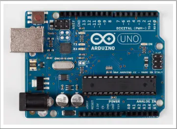
Arduino Hardware
The Arduino Uno has a second microcontroller onboard to handle all USB communi-cation; the small surface-mount chip (the ATmega8U2) is located near the USB socket on the board. This can be programmed separately to enable the board to appear as different USB devices (see Recipe 18.14 for an example). The Arduino Leonardo board replaces the ATmega8U2 and the ATmega328 controllers with a single ATmega32u4 chip that implements the USB protocol in software. The Arduino-compatible Teensy and Teensy+ boards from PJRC (http://www.pjrc.com/teensy/) are also capable of em-ulating USB devices. Older boards, and most of the Arduino-compatible boards, use a chip from the FTDI company that provides a hardware USB solution for connection to the serial port of your computer.
You can get boards as small as a postage stamp, such as the Arduino Mini and Pro Mini; larger boards that have more connection options and more powerful processors, such as the Arduino Mega; and boards tailored for specific applications, such as the LilyPad for wearable applications, the Fio for wireless projects, and the Arduino Pro for em-bedded applications (standalone projects that are often battery-operated).
Recent additions to the range include the Arduino ADK, which has a USB host socket on it and is compatible with the Android Open Accessory Development Kit, the offi-cially approved method of attaching hardware to Android devices. The Leonardo board uses a controller chip (the ATmega32u4) that is able to present itself as various HID
Figure 1-1. Basic board: the Arduino Uno. Photograph courtesy todo.to.it.
devices. The Ethernet board includes Ethernet connectivity, and has a Power Over Ethernet option, so it is possible to use a single cable to connect and power the board. Other Arduino-compatible boards are also available, including the following:
• Arduino Nano, a tiny board with USB capability, from Gravitech (http://store.grav itech.us/arna30wiatn.html)
• Bare Bones Board, a low-cost board available with or without USB capability, from
Modern Device (http://www.moderndevice.com/products/bbb-kit)
• Boarduino, a low-cost breadboard-compatible board, from Adafruit Industries (http://www.adafruit.com/)
• Seeeduino, a flexible variation of the standard USB board, from Seeed Studio Bazaar (http://www.seeedstudio.com/)
• Teensy and Teensy++, tiny but extremely versatile boards, from PJRC (http://www .pjrc.com/teensy/)
A list of Arduino-compatible boards is available at http://www.freeduino.org/.
See Also
An overview of Arduino boards: http://www.arduino.cc/en/Main/Hardware.
Online guides for getting started with Arduino are available at http://arduino.cc/en/ Guide/Windows for Windows, http://arduino.cc/en/Guide/MacOSX for Mac OS X, and
http://www.arduino.cc/playground/Learning/Linux for Linux.
A list of over a hundred boards that can be used with the Arduino development envi-ronment can be found at: http://jmsarduino.blogspot.com/2009/03/comprehensive-ardu ino-compatible.html
1.1 Installing the Integrated Development Environment (IDE)
Problem
You want to install the Arduino development environment on your computer.
Solution
The Arduino software for Windows, Mac, and Linux can be downloaded from http://
arduino.cc/en/Main/Software.
The Windows download is a ZIP file. Unzip the file to any convenient directory—
A free utility for unzipping files, called 7-Zip, can be downloaded from http://www.7-zip.org/.
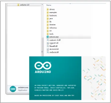
Unzipping the file will create a folder named Arduino-00<nn> (where <nn> is the ver-sion number of the Arduino release you downloaded). The directory contains the executable file (named Arduino.exe), along with various other files and folders. Double-click the Arduino.exe file and the splash screen should appear (see Figure 1-2), followed by the main program window (see Figure 1-3). Be patient, as it can take some time for the software to load.
Figure 1-2. Arduino splash screen (Version 1.0 in Windows 7)
The Arduino download for the Mac is a disk image (.dmg); double-click the file when the download is complete. The image will mount (it will appear like a memory stick
on the desktop). Inside the disk image is the Arduino application. Copy this to somewhere convenient—the Applications folder is a sensible place. Double-click the application once you have copied it over (it is not a good idea to run it from the disk image). The splash screen will appear, followed by the main program window. Linux installation varies depending on the Linux distribution you are using. See the Arduino wiki for information (http://www.arduino.cc/playground/Learning/Linux). To enable the Arduino development environment to communicate with the board, you need to install drivers.
On Windows, use the USB cable to connect your PC and the Arduino board and wait for the Found New Hardware Wizard to appear. If you are using an Uno board, let the wizard attempt to find and install drivers. It will fail to do this (don’t worry, this is the expected behavior). To fix it you now need to go to Start Menu→Control Panel→System
and Security. Click on System, and then open Device Manager. In the listing that is displayed find the entry in COM and LPT named Arduino UNO (COM nn). nn will be the number Windows has assigned to the port created for the board. You will see a warning logo next to this because the appropriate drivers have not yet been assigned. Right click on the entry and select Update Driver Software. Choose the “Browse my computer for driver software” option, and navigate to the Drivers folder inside the Arduino folder you just unzipped. Select the ArduinoUNO.inf file and windows should then complete the installation process.
If you are using an earlier board (any board that uses FTDI drivers) with Windows Vista or Windows 7 and are online, you can let the wizard search for drivers and they will install automatically. On Windows XP (or if you don’t have Internet access), you should specify the location of the drivers. Use the file selector to navigate to the FTDI USB Drivers directory, located in the directory where you unzipped the Arduino files. When this driver has installed, the Found New Hardware Wizard will appear again, saying a new serial port has been found. Follow the same process as before.
It is important that you go through the sequence of steps to install the drivers two times, or the software will not be able to communicate with the board.
On the Mac, the latest Arduino boards, such as the Uno, can be used without additional drivers. When you first plug the board in a notification will pop up saying a new net-work port has been found, you can dismiss this. If you are using earlier boards (boards that need FTDI drivers), you will need to install driver software. There is a package named FTDIUSBSerialDriver, with a range of numbers after it, inside the disk image. Double-click this and the installer will take you through the process. You will need to know an administrator password to complete the process.
On Linux, most distributions have the driver already installed, but follow the Linux link given in this chapter’s introduction for specific information for your distribution.
Discussion
If the software fails to start, check the troubleshooting section of the Arduino website,
http://arduino.cc/en/Guide/Troubleshooting, for help solving installation problems.
See Also
Online guides for getting started with Arduino are available at http://arduino.cc/en/ Guide/Windows for Windows, http://arduino.cc/en/Guide/MacOSX for Mac OS X, and
http://www.arduino.cc/playground/Learning/Linux for Linux.
1.2 Setting Up the Arduino Board
Problem
You want to power up a new board and verify that it is working.
Solution
Plug the board in to a USB port on your computer and check that the green LED power indicator on the board illuminates. Standard Arduino boards (Uno, Duemilanove, and Mega) have a green LED power indicator located near the reset switch.
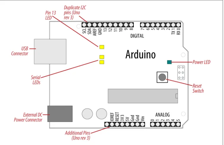
An orange LED near the center of the board (labeled “Pin 13 LED” in Figure 1-4) should flash on and off when the board is powered up (boards come from the factory preloaded with software to flash the LED as a simple check that the board is working).
Figure 1-4. Basic Arduino board (Duemilanove and Uno)
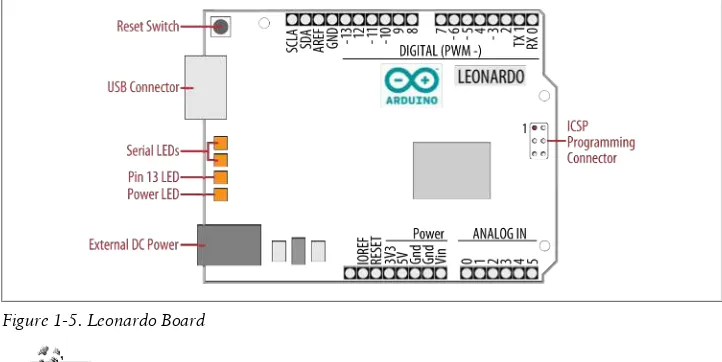
New boards such as Leonardo have the LEDs located near the USB connector; see
The latest boards have three additional connections in the new standard for connector layout on the board. This does not affect the use of older shields (they will all continue to work with the new boards, just as they did with earlier boards). The new connections provide a pin (IOREF) for shields to detect the analog reference voltage (so that analog input values can be calibrated to the supply voltage), SCL and SDA pins to enable a consistent connection for I2C devices (the location of the I2C pins has differed on previous boards due to different chip configura-tions). Shields designed for the new layout should work on any board that uses the new pin locations. An additional pin (next to the IOREF pin) is not being used at the moment, but enables new functionality to be implemented in the future without needing to change the pin layout again.
Discussion
If the power LED does not illuminate when the board is connected to your computer, the board is probably not receiving power.
The flashing LED (connected to digital output pin 13) is being controlled by code running on the board (new boards are preloaded with the Blink example sketch). If the pin 13 LED is flashing, the sketch is running correctly, which means the chip on the board is working. If the green power LED is on but the pin 13 LED is not flashing, it could be that the factory code is not on the chip; follow the instructions in Rec-ipe 1.3 to load the Blink sketch onto the board to verify that the board is working. If you are not using a standard board, it may not have a built-in LED on pin 13, so check the documentation for details of your board. The Leonardo board fades the LED up and down (it looks like the LED is “breathing”) to show that the board is working.
Figure 1-5. Leonardo Board
See Also
Online guides for getting started with Arduino are available at http://arduino.cc/en/ Guide/Windows for Windows, http://arduino.cc/en/Guide/MacOSX for Mac OS X, and
http://www.arduino.cc/playground/Learning/Linux for Linux.
A troubleshooting guide can be found at http://arduino.cc/en/Guide/Troubleshooting.
1.3 Using the Integrated Development Environment (IDE) to
Prepare an Arduino Sketch
Problem
You want to get a sketch and prepare it for uploading to the board.
Solution
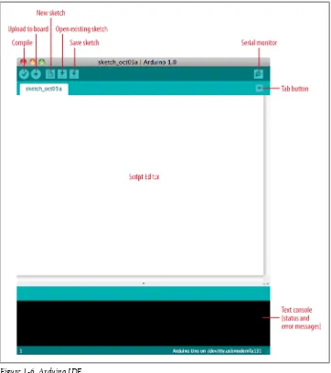
Use the Arduino IDE to create, open, and modify sketches that define what the board will do. You can use buttons along the top of the IDE to perform these actions (shown in Figure 1-6), or you can use the menus or keyboard shortcuts (shown in Figure 1-7). The Sketch Editor area is where you view and edit code for a sketch. It supports com-mon text-editing keys such as Ctrl-F (⌘+F on a Mac) for find, Ctrl-Z (⌘+Z on a Mac) for undo, Ctrl-C (⌘+C on a Mac) to copy highlighted text, and Ctrl-V (⌘+V on a Mac) to paste highlighted text.
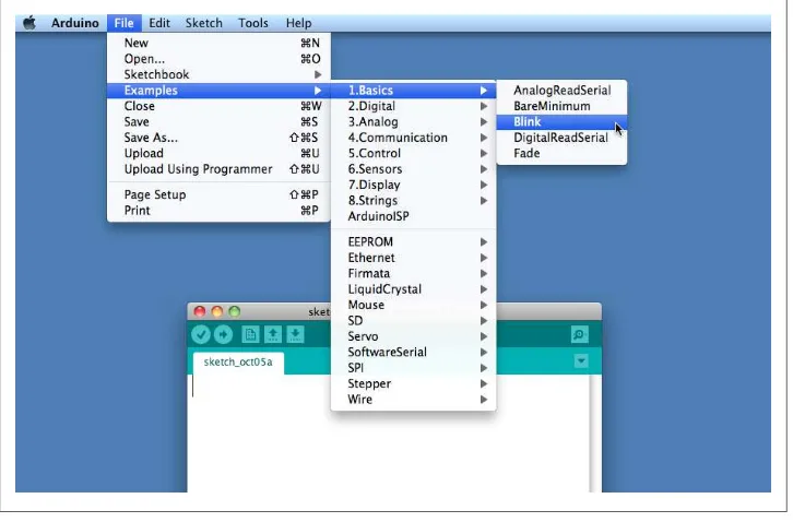
Figure 1-7 shows how to load the Blink sketch (the sketch that comes preloaded on a new Arduino board).
After you’ve started the IDE, go to the File→Examples menu and select 1. Basics→Blink, as shown in Figure 1-7. The code for blinking the built-in LED will be displayed in the Sketch Editor window (refer to Figure 1-6).
Before the code can be sent to the board, it needs to be converted into instructions that can be read and executed by the Arduino controller chip; this is called compiling. To do this, click the compile button (the top-left button with a tick inside), or select Sketch→Verify/Compile (Ctrl-R; ⌘+R on a Mac).
You should see a message that reads “Compiling sketch...” and a progress bar in the message area below the text-editing window. After a second or two, a message that reads “Done Compiling” will appear. The black console area will contain the following additional message:
Binary sketch size: 1026 bytes (of a 32256 byte maximum)
Discussion
Source code for Arduino is called a sketch. The process that takes a sketch and converts it into a form that will work on the board is called compilation. The IDE uses a number of command-line tools behind the scenes to compile a sketch. For more information on this, see Recipe 17.1.
The final message telling you the size of the sketch indicates how much program space is needed to store the controller instructions on the board. If the size of the compiled
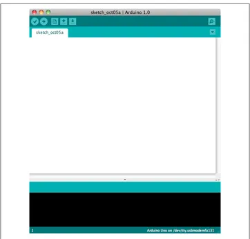
Figure 1-6. Arduino IDE
sketch is greater than the available memory on the board, the following error message is displayed:
Sketch too big; see http://www.arduino.cc/en/Guide/Troubleshooting#size for tips on reducing it.
If this happens, you need to make your sketch smaller to be able to put it on the board, or get a board with higher capacity.
If there are errors in the code, the compiler will print one or more error messages in the console window. These messages can help identify the error—see Appendix D on soft-ware errors for troubleshooting tips.
To prevent accidental overwriting of the examples, the Arduino IDE does not allow you to save changes to the provided example sketches. You must rename them using the Save As menu option. You can save sketches you write yourself with the Save button (see Recipe 1.5).
As you develop and modify a sketch, you should also consider using the File→Save As menu option and using a different name or version number regularly so that as you implement each bit, you can go back to an older version if you need to.
Code uploaded onto the board cannot be downloaded back onto your computer. Make sure you save your sketch code on your computer. You cannot save changes back to the example files; you need to use Save As and give the changed file another name.
See Also
Recipe 1.5 shows an example sketch. Appendix D has tips on troubleshooting software problems.
1.4 Uploading and Running the Blink Sketch
Problem
You want to transfer your compiled sketch to the Arduino board and see it working.
Solution
Connect your Arduino board to your computer using the USB cable. Load the Blink sketch into the IDE as described in Recipe 1.3.
Next, select Tools→Board from the drop-down menu and select the name of the board you have connected (if it is the standard Uno board, it is probably the first entry in the board list).
Now select Tools→Serial Port. You will get a drop-down list of available serial ports on your computer. Each machine will have a different combination of serial ports, de-pending on what other devices you have used with your computer.
On Windows, they will be listed as numbered COM entries. If there is only one entry, select it. If there are multiple entries, your board will probably be the last entry. On the Mac, your board will be listed twice if it is an Uno board:
/dev/tty.usbmodem-XXXXXXX /dev/cu.usbmodem-XXXXXXX
If you have an older board, it will be listed as follows:
/dev/tty.usbserial-XXXXXXX /dev/cu.usbserial-XXXXXXX
Each board will have different values for XXXXXXX. Select either entry.
Click on the upload button (in Figure 1-6, it’s the second button from the left), or choose File→Upload to I/O board (Ctrl-U, ⌘+U on a Mac).
The software will compile the code, as in Recipe 1.3. After the software is compiled, it is uploaded to the board. If you look at your board, you will see the LED stop flashing, and two lights (labeled as Serial LEDs in Figure 1-4) just below the previously flashing
LED should flicker for a couple of seconds as the code uploads. The original light should then start flashing again as the code runs.
Discussion
For the IDE to send the compiled code to the board, the board needs to be plugged in to the computer, and you need to tell the IDE which board and serial port you are using. When an upload starts, whatever sketch is running on the board is stopped (if you were running the Blink sketch, the LED will stop flashing). The new sketch is uploaded to the board, replacing the previous sketch. The new sketch will start running when the upload has successfully completed.
Older Arduino boards and some compatibles do not automatically in-terrupt the running sketch to initiate upload. In this case, you need to press the Reset button on the board just after the software reports that it is done compiling (when you see the message about the size of the sketch). It may take a few attempts to get the timing right between the end of the compilation and pressing the Reset button.
The IDE will display an error message if the upload is not successful. Problems are usually due to the wrong board or serial port being selected or the board not being plugged in. The currently selected board and serial port are displayed in the status bar at the bottom of the Arduino window
If you have trouble identifying the correct port on Windows, try unplugging the board and then selecting Tools→Serial Port to see which COM port is no longer on the display list. Another approach is to select the ports, one by one, until you see the lights on the board flicker to indicate that the code is uploading.
See Also
The Arduino troubleshooting page: http://www.arduino.cc/en/Guide/Troubleshooting.
1.5 Creating and Saving a Sketch
Problem
You want to create a sketch and save it to your computer.
Solution
const int ledPin = 13; // LED connected to digital pin 13
void setup() {
pinMode(ledPin, OUTPUT); }
void loop() {
digitalWrite(ledPin, HIGH); // set the LED on delay(2000); // wait for two seconds digitalWrite(ledPin, LOW); // set the LED off delay(2000); // wait for two seconds }
Compile the code by clicking the compile button (the top-left button with a triangle inside), or select Sketch→Verify/Compile (see Recipe 1.3).
Upload the code by clicking on the upload button, or choose File→Upload to I/O board (see Recipe 1.4). After uploading, the LED should blink, with each flash lasting two seconds.
You can save this sketch to your computer by clicking the Save button, or select File→Save.
You can save the sketch using a new name by selecting the Save As menu option. A dialog box will open where you can enter the filename.
Discussion
When you save a file in the IDE, a standard dialog box for the operating system will open. It suggests that you save the sketch to a folder called Arduino in your My Docu-ments folder (or your Documents folder on a Mac). You can replace the default sketch name with a meaningful name that reflects the purpose of your sketch. Click Save to save the file.
The default name is the word sketch followed by the current date. Se-quential letters starting from a are used to distinguish sketches created on the same day. Replacing the default name with something meaning-ful helps you to identify the purpose of a sketch when you come back to it later.
If you use characters that the IDE does not allow (e.g., the space character), the IDE will automatically replace these with valid characters.
Arduino sketches are saved as plain text files with the extension .ino. Older versions of the IDE used the .pde extension, also used by Processing. They are automatically saved in a folder with the same name as the sketch.
You can save your sketches to any folder on your computer, but if you use the default folder (the Arduino folder in your Documents folder) your sketches will automatically appear in the Sketchbook menu of the Arduino software and be easier to locate.
If you have edited one of the examples from the Arduino download, you will not be able to save the changed file using the same filename. This preserves the standard examples intact. If you want to save a modified example, you will need to select another location for the sketch.
After you have made changes, you will see a dialog box asking if you want to save the sketch when a sketch is closed.
The § symbol following the name of the sketch in the top bar of the IDE window indicates that the sketch code has changes that have not yet been saved on the computer. This symbol is removed when you save the sketch.
The Arduino software does not provide any kind of version control, so if you want to be able to revert to older versions of a sketch, you can use Save As regularly and give each revision of the sketch a slightly different name.
Frequent compiling as you modify or add code is a good way to check for errors as you write your code. It will be easier to find and fix any errors because they will usually be associated with what you have just written.
Once a sketch has been uploaded onto the board there is no way to download it back to your computer. Make sure you save any changes to your sketches that you want to keep.
If you try and save a sketch file that is not in a folder with the same name as the sketch, the IDE will inform you that this can’t be opened as is and suggest you click OK to create the folder for the sketch with the same name.
See Also
The code in this recipe and throughout this book use the const int expression to provide meaningful names (ledPin) for constants instead of numbers (13). See
Recipe 17.5 for more on the use of constants.
1.6 Using Arduino
Problem
You want to get started with a project that is easy to build and fun to use.
Solution
This recipe provides a taste of some of the techniques that are covered in detail in later chapters.
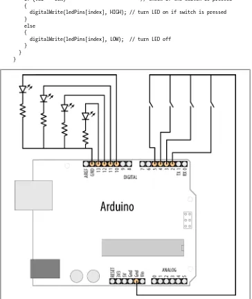
The sketch is based on the LED blinking code from the previous recipe, but instead of using a fixed delay, the rate is determined by a light-sensitive sensor called a light de-pendent resistor or LDR (see Recipe 6.2). Wire the LDR as shown in Figure 1-8.
Figure 1-8. Arduino with light dependent resistor
If you are not familiar with building a circuit from a schematic, see Appendix B for step-by-step illustrations on how to make this circuit on a breadboard.
The following sketch reads the light level of an LDR connected to analog pin 0. The light level striking the LDR will change the blink rate of the internal LED connected to pin 13:
const int ledPin = 13; // LED connected to digital pin 13 const int sensorPin = 0; // connect sensor to analog input 0
void setup() {
pinMode(ledPin, OUTPUT); // enable output on the led pin }
void loop() {
int rate = analogRead(sensorPin); // read the analog input digitalWrite(ledPin, HIGH); // set the LED on
delay(rate); // wait duration dependent on light level digitalWrite(ledPin, LOW); // set the LED off
delay(rate); }
Discussion
The value of the 4.7K resistor is not critical. Anything from 1K to 10K can be used. The light level on the LDR will change the voltage level on analog pin 0. The analogRead command (see Chapter 6) provides a value that ranges from around 200 when the LDR is dark to 800 or so when it is very bright. This value determines the duration of the LED on and off times, so the blink time increases with light intensity.
You can scale the blink rate by using the Arduino map function as follows:
const int ledPin = 13; // LED connected to digital pin 13 const int sensorPin = 0; // connect sensor to analog input 0
// the next two lines set the min and max delay between blinks const int minDuration = 100; // minimum wait between blinks const int maxDuration = 1000; // maximum wait between blinks
void setup() {
pinMode(ledPin, OUTPUT); // enable output on the led pin }
void loop() {
digitalWrite(ledPin, HIGH); // set the LED on
delay(rate); // wait duration dependent on light level digitalWrite(ledPin, LOW); // set the LED off
delay(rate); }
Recipe 5.7 provides more details on using the map function to scale values. Recipe 3.5
has details on using the constrain function to ensure values do not exceed a given range. If you want to view the value of the rate variable on your computer, you can print this to the Arduino Serial Monitor as shown in the revised loop code that follows. The sketch will display the blink rate in the Serial Monitor. You open the Serial Monitor window in the Arduino IDE by clicking on the icon on the right of the top bar (see
Chapter 4 for more on using the Serial Monitor):
const int ledPin = 13; // LED connected to digital pin 13 const int sensorPin = 0; // connect sensor to analog input 0
// the next two lines set the min and max delay between blinks const int minDuration = 100; // minimum wait between blinks const int maxDuration = 1000; // maximum wait between blinks
void setup() {
pinMode(ledPin, OUTPUT); // enable output on the led pin Serial.begin(9600); // initialize Serial
}
void loop() {
int rate = analogRead(sensorPin); // read the analog input // the next line scales the blink rate between the min and max values rate = map(rate, 200,800,minDuration, maxDuration); // convert to blink rate rate = constrain(rate, minDuration,maxDuration); // constrain the value
Serial.println(rate); // print rate to serial monitor digitalWrite(ledPin, HIGH); // set the LED on
delay(rate); // wait duration dependent on light level digitalWrite(ledPin, LOW); // set the LED off
delay(rate); }
You can use the LDR to control the pitch of a sound by connecting a small speaker to the pin, as shown in Figure 1-9.
Figure 1-9. Connections for a speaker with the LDR circuit
You will need to increase the on/off rate on the pin to a frequency in the audio spectrum. This is achieved, as shown in the following code, by decreasing the min and max durations:
const int outputPin = 9; // Speaker connected to digital pin 9 const int sensorPin = 0; // connect sensor to analog input 0
const int minDuration = 1; // 1ms on, 1ms off (500 Hz) const int maxDuration = 10; // 10ms on, 10ms off (50 hz)
void setup() {
pinMode(outputPin, OUTPUT); // enable output on the led pin }
void loop() {
int sensorReading = analogRead(sensorPin); // read the analog input int rate = map(sensorReading, 200,800,minDuration, maxDuration);
rate = constrain(rate, minDuration,maxDuration); // constrain the value
digitalWrite(outputPin, HIGH); // set the LED on
delay(rate); // wait duration dependent on light level digitalWrite(outputPin, LOW); // set the LED off
See Also
See Recipe 3.5 for details on using the constrain function. See Recipe 5.7 for a discussion on the map function.
If you are interested in creating sounds, see Chapter 9 for a full discussion on audio output with Arduino.
CHAPTER 2
Making the Sketch Do Your Bidding
2.0 Introduction
Though much of an Arduino project will involve integrating the Arduino board with supporting hardware, you need to be able to tell the board what to do with the rest of your project. This chapter introduces core elements of Arduino programming, shows nonprogrammers how to use common language constructs, and provides an overview of the language syntax for readers who are not familiar with C or C++, the language that Arduino uses.
Since making the examples interesting requires making Arduino do something, the recipes use physical capabilities of the board that are explained in detail in later chap-ters. If any of the code in this chapter is not clear, feel free to jump forward, particularly to Chapter 4 for more on serial output and Chapter 5 for more on using digital and analog pins. You don’t need to understand all the code in the examples, though, to see how to perform the specific capabilities that are the focus of the recipes. Here are some of the more common functions used in the examples that are covered in the next few chapters:
Serial.println(value);
Prints the value to the Arduino IDE’s Serial Monitor so you can view Arduino’s output on your computer; see Recipe 4.1.
pinMode(pin, mode);
Configures a digital pin to read (input) or write (output) a digital value; see the
introduction to Chapter 5. digitalRead(pin);
Reads a digital value (HIGH or LOW) on a pin set for input; see Recipe 5.1. digitalWrite(pin, value);
Writes the digital value (HIGH or LOW) to a pin set for output; see Recipe 5.1.
2.1 Structuring an Arduino Program
Problem
You are new to programming and want to understand the building blocks of an Arduino program.
Solution
Programs for Arduino are usually referred to as sketches; the first users were artists and designers and sketch highlights the quick and easy way to have an idea realized. The terms sketch and program are interchangeable. Sketches contain code—the instructions the board will carry out. Code that needs to run only once (such as to set up the board for your application) must be placed in the setup function. Code to be run continuously after the initial setup has finished goes into the loop function. Here is a typical sketch:
const int ledPin = 13; // LED connected to digital pin 13
// The setup() method runs once, when the sketch starts void setup()
{
pinMode(ledPin, OUTPUT); // initialize the digital pin as an output }
// the loop() method runs over and over again, void loop()
{
digitalWrite(ledPin, HIGH); // turn the LED on delay(1000); // wait a second digitalWrite(ledPin, LOW); // turn the LED off delay(1000); // wait a second }
When the Arduino IDE finishes uploading the code, and every time you power on the board after you’ve uploaded this code, it starts at the top of the sketch and carries out the instructions sequentially. It runs the code in setup once and then goes through the code in loop. When it gets to the end of loop (marked by the closing bracket, }) it goes back to the beginning of loop.