For your convenience Apress has placed some of the front
matter material after the index. Please use the Bookmarks
and Contents at a Glance links to access them.
Contents at a Glance
Contents...vii
About the Authors... xvii
About the Technical Reviewer ... xviii
Acknowledgments ... xix
Introduction ... xx
Chapter 1: Arduino Basics ...1
Chapter 2: Kinect Basics...23
Chapter 3: Processing...35
Chapter 4: Arduino and Kinect: “Hello World” ...61
Chapter 5: Kinect Remote Control...77
Chapter 6: Kinect Networked Puppet...99
Chapter 7: Mood Lamps ...133
Chapter 8: Kinect-Driven Drawing Robot ...167
Chapter 9: Kinect Remote-Controlled Vehicles ...207
Chapter 10: Biometric Station...243
Chapter 11: 3D Modeling Interface ...279
Chapter 12: Turntable Scanner ...309
Chapter 13: Kinect-Controlled Delta Robot ...343
INTRODUCTION
xx
Introduction
If you've done some Arduino tinkering and wondered how you could incorporate the Kinect in your projects — or the other way around — this book is for you.
If you haven’t actually done any tinkering but you are looking for a good way to get started, this book might also be for you. Even though this is not intended as an introductory book, we have tried to assume as little knowledge from the reader as possible, starting from the installation of every tool you will be using and thoroughly explaining every new concept appearing in the book.
The Structure of This Book
This is a practical book. As such, you are going to be driven through a series of projects evolving from simple to complex, learning all you need to know along the way. The book starts with three introductory chapters oriented to getting you acquainted with Arduino, Kinect, and Processing in the least amount of time possible so you can go straight into building cool projects. From Chapter 4, you will be led through a series of 10 fun projects increasing in complexity, starting with the Arduino and Kinect equivalent of "Hello World" and finishing with the construction and programming of a Kinect-driven delta robot.
The Content of the Chapters
Each chapter will lead you step-by-step through the construction of the physical project, the building of the necessary circuits, the programming of the Arduino board, and the implementation of the
Processing programs that connect the Kinect data to your Arduino board. Most projects will involve the implementation of two separate programs, the Arduino program and the Processing program. Arduino code will be displayed in bold monospace typeface, like this:
digitalRead(A0); // This is Arduino Code
Processing programs will be written in normal monospace font style, like this:
fill(255,0,0); // This is Processing Code
In each chapter, you will be introduced to the specific concepts and techniques that you will need to build that particular project—and probably some of the following ones. If you are an experienced programmer, you might want to read this book non-sequentially, starting by the project that interests you the most. If you are a programming beginner, you will find it easier to start with the first project and build up your knowledge as you progress through the book.
This is a list of topics that will be introduced in each chapter, so if you are interested in a specific concept you can jump straight to the right project.
• Chapter 1: You will learn everything you need to know about the Arduino platform, you will install the necessary drivers and software, and you will write your first Arduino program.
INTRODUCTION
• Chapter 3: You will discover the Processing programming language and IDE. You will install Processing, build your first Processing programs, and learn a great deal about working in 3D.
• Chapter 4: You will learn about communicating with Arduino and Kinect through serial, you will develop your own communication protocol, and you will use hand tracking for the first time. You will also learn how to use pulse width modulation and how to work with LEDs and light sensors.
• Chapter 5: This chapter will teach you to hack a remote control and use body gestures to control your TV set. You will learn how to use relays and how to build a circuit on a prototyping shield. You will even develop your own gesture
recognition routine.
• Chapter 6: You will learn to work with servos and how to communicate through networks and over the Internet. You will also use Kinect’s skeleton tracking capabilities to drive a puppet with your body gestures.
• Chapter 7: The Arduino Nano and the XBee wireless module will be introduced in this chapter. You will also learn all about resistors and color LEDs. You will take the skeleton tracking to three dimensions and use it to control a series of lamps responding to your presence.
• Chapter 8: Przemek Jaworski has contributed this amazing drawing arm project. In this chapter, you will work with Firmata, a library that allows you to control the Arduino from Processing without the need to write any Arduino code. You will also learn how to build a tangible table to control your robotic arm.
• Chapter 9: You will be introduced to DC motors and how to control them using H-bridges. You will also learn how to use proximity sensors. You will use all these techniques to control a RC car with hand gestures.
• Chapter 10: This project will teach you how to hack a bathroom scale to provide user weight data wirelessly. You will learn how to acquire data from a seven-segment LCD display, and you will then combine the data with the Kinect skeleton tracking to implement user recognition and body mass index calculation.
• Chapter 11: You will build a wireless, wearable circuit on a glove using the Arduino LilyPad, flex sensors, and an XBee module. You will then implement your own simple computer-assisted design (CAD) software, and you will use your wireless interface to draw 3D geometries by moving your hand in space.
• Chapter 12: This chapter will teach you to parse, transform, and recompose raw point clouds in order to perform 360-degreee scans of objects using just one Kinect and a turntable that you will build. Then you will learn how to write your own .ply file export routine and how to import the point data into Meshlab to prepare it to be 3D printed or rendered.
• Chapter 13: This final project will teach you the basics of inverse kinematics and how to use all the techniques from throughout the book to build a Kinect-controlled delta robot.
INTRODUCTION
xxii
to consider having a reference book at hand. John Vince’s Mathematics for Computer Graphics (Springer, 2006) is an amazing resource. Web sites like Wolfram Alpha (www.wolframalpha.com) or mathWorld (http://mathworld.wolfram.com) can be helpful as well.
Every chapter will include the necessary code to make the project work. You can copy this code from the book or you can download the necessary files from Apress (www.apress.com) or the book’s web site (www.arduinoandkinectprojects.com).
If you need to contact the authors, you can find us via the following addresses:
• Enrique Ramos Melgar: [email protected]
• Ciriaco Castro Díez: [email protected]
C H A P T E R 1
Arduino Basics
by Enrique Ramos
This first chapter is dedicated to Arduino, one of the two cornerstones of this book. The following pages cover the basics of the Arduino hardware and software. By the end of the chapter, you will have installed the platform on your computer and you will have programmed two examples using the Arduino
integrated development environment (IDE).
The structure of an Arduino sketch will be analyzed and each function explained. You will learn about the Arduino input and output pins. You will also learn the basic concepts of electricity, circuits, and prototyping techniques that you will be using throughout the book.
It is highly likely that this is not the first book on Arduino that you have held in your hands. If you are an experienced Arduino user, you should consider reading these pages as a refresher. If you are a complete beginner, read carefully!
CHAPTER 1 ARDUINO BASICS
2
What is Arduino?
Arduino is an open source electronics prototyping platform composed of a microcontroller, a
programming language, and an IDE. Arduino is a tool for making interactive applications, designed to simplify this task for beginners but still flexible enough for experts to develop complex projects.
Since its inception in 2005, more than 200,000 Arduino boards (see Figure 1-1) have been sold, and there is a rapidly increasing number of projects using Arduino as their computing core. The Arduino community is vast, and so is the number of tutorials, reference books, and libraries available. Being open source means that there are Arduino clones that you can choose for your projects. Advanced Arduino users are constantly developing shields for the available Arduinos as well as completely new Arduino-compatible boards specializing in different tasks.
The intentional simplicity of approach to the Arduino platform has permitted an access to physical computing for people who would have never thought of using or programming a microcontroller before the Arduino/Wiring era.
A Brief History of Arduino
Arduino was born in 2005 at the Interaction Design Institute Ivrea, Italy, as a fork of the open source Wiring Platform. The founders of the project, Massimo Banzi and David Cuartielles, named the project after Arduin of Ivrea, the main historical character of the town.
Hernando Barragán, a student at the same Institute, along with Diego Gonzalez Joven, had
developed Wiring in 2003 as his master’s thesis, which was supervised by Massimo Banzi and Casey Reas (one of the initiators of Processing). The idea behind Wiring was to allow an easy introduction to
programming and sketching with electronics for artists and designers—in a similar mindset in which Casey Reas and Ben Fry had developed Processing some years earlier (you will learn more on the history of Processing in Chapter 3).
Arduino was built around Wiring but developed independently from 2005. The two projects are still very much alive, so everything you will be doing in this book with Arduino could also be done with Wiring boards and IDE.
Installing Arduino
The first thing you need to do if you want to work with Arduino is to buy an Arduino board and a standard USB cable (A-to-B plug if you are using an Arduino Uno). Well, of course you will need more than this if you want to build any reasonable useful application, but for the moment you’ll just work with the bare essentials.
Arduino runs on Windows, Mac OS X, and Linux, so there’s a version of Arduino for you whatever your OS. Go to the Arduino software web site at http://arduino.cc/en/Main/Software and download the version of the software compatible with your system. If after reading the following sections you are still having trouble with the installation, you can have more detailed information at
http://arduino.cc/en/Guide/HomePage.
Installation on Mac OS X
CHAPTER 1 ARDUINO BASICS
If you are using a board older than Arduino Uno (Duemilanove, Diecimila, or older), you need to install the drivers for the FTDI chip on the board. You can find the drivers and the instructions at http://www.arduino.cc/en/Guide/MacOSX.
Installation on Windows
First, download the Windows .zip file and uncompress it. You will see a folder called arduino-1.0. This is your Arduino folder and you need to store it somewhere in the computer from where you can later run the program. The Program Files folder would seem like a reasonable place for the Arduino software, but feel free to choose an alternative location.
You need to install the Arduino drivers before you can start working with your board. Assuming you are installing an Arduino Uno, follow these steps:
• Plug your board to your computer, and wait for Windows to start the driver installation process. After a while, it will fail. No problem.
• Click Start menu and open the Control Panel.
• Go to System and Security, then System and then Device Manager. • Find the Arduino Uno port listed under Ports (COM & LPT).
• Right-click on it, and choose “Update Driver Software,” selecting “Browse my Computer for Driver Software.”
• Finally, navigate and select the Arduino Uno’s driver file named ArduinoUNO.inf located in the Drivers folder of the Arduino software folder you have just downloaded. Windows will successfully install the board now.
Installation on Linux
If you are working on Linux, the installation process is slightly different depending on your Linux distribution, and unfortunately we don’t have the space to detail all of them in this book. You can find all the information you need at http://www.arduino.cc/playground/Learning/Linux.
Testing the Arduino
Once you have installed the Arduino software and drivers, you need to perform a little test to make sure that everything is working properly.
Arduino has a built-in LED connected to pin 13, so you can actually test the board without having to connect any extra hardware to it. Among the numerous Arduino examples included with the Arduino IDE, there is an example called Blink that makes this built-in LED to blink every second. You will learn more about pins, LEDs, and Arduino code in the following sections, but for the moment, you are going to use this example as a way to find out if your Arduino is communicating properly with your computer and if the sketches can be uploaded to the board.
CHAPTER 1 ARDUINO BASICS
4
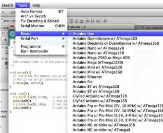
Figure 1-2. Board selection
After this, select the serial device under the Serial Port option in your Tools menu. If you are working on Mac OS X, the port should be something with /dev/tty.usbmodem (for the Uno or Mega 2560) or
/dev/tty.usbserial (for older boards) in it (see Figure 1-3). If you are using Windows, the port is likely to be COM 3 or higher.
CHAPTER 1 ARDUINO BASICS
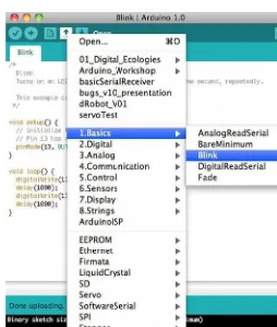
Now everything should be ready for you to upload your first program to your Arduino board. You will be using one of the classic Arduino examples for this test. Click the Open button on your toolbar and navigate to 1.Basics Blink, as shown in Figure 1-4. Then upload the sketch by clicking the Upload button (the one with the arrow pointing right on your toolbar). After some seconds, you will get a message saying “Done Uploading” on the status bar, and the LED marked with a capital “L” on your board will start blinking every second. If you succeeded in this, your Arduino is correctly set up, and you can move on to learning about the Arduino hardware and software.
Figure 1-4. Opening the Blink example
Arduino Hardware
CHAPTER 1 ARDUINO BASICS
6
Note A microcontroller is just a small computer designed for embedded applications, like controlling devices, machines, appliances, and toys. Atmel AVR is an 8-bit single chip microcontroller developed by Atmel in 1996.
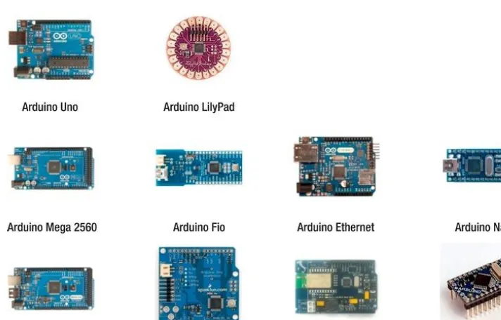
If you go to http://arduino.cc/en/Main/Hardware, you will find a surprisingly vast range of Arduino boards. Each one of them has been designed with a different purpose in mind and thus has different amount of pins and electronics on board (see Figure 1-5).
The Arduino Uno is, at the time of writing, the simplest Arduino board to use. For the rest of the book, whenever we refer to Arduino board, we actually mean an Arduino Uno unless explicitly stated (we will also work with Arduino Nano and Arduino Lilypad in further chapters).
Figure 1-5. Official Arduino boards (from http://arduino.cc)
CHAPTER 1 ARDUINO BASICS
Arduino Input and Output Pins
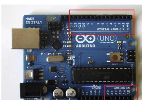
The Arduino Uno has 14 digital input/output pins and six analog input pins, as shown in Figure 1-6. As mentioned, these pins correspond to the input/output pins on your ATmega microcontroller. The architecture of the Arduino board exposes these pins so they can be easily connected to external circuits.
Arduino pins can be set up in two modes: input and output. The ATmega pins are set to input by default, so you don’t need to explicitly set any pins as inputs in Arduino, although you will often do this in your code for clarity.
Figure 1-6. Arduino digital pins (top) and analog pins (bottom)
Digital Pins
Arduino has 14 digital pins, numbered from 0 to 13. The digital pins can be configured as INPUT or OUTPUT, using the pinMode() function. On both modes, the digital pins can only send or receive digital signals, which consist of two different states: ON (HIGH, or 5V) and OFF (LOW, or 0V).
Pins set as OUTPUT can provide current to external devices or circuits on demand. Pins set as INPUT are ready to read currents from the devices connected to them. In further chapters, you will learn how to set these pins to INPUT so you can read the state of a switch, electric pulses, and other digital signals. You will also learn how to work with digital pins set as OUTPUT to turn LED lights on and off, drive motors, control systems, and other devices.
Six of these pins can also be used as pulse width modulation pins (PWM). Chapter 4 covers what this means and how to use PWM pins.
Analog Input Pins
CHAPTER 1 ARDUINO BASICS
8
potential) into a digital number proportional to the magnitude of the input voltage in relation to the reference voltage (5V).
The ATmega converter on your Arduino board has 10-bit resolution, which means it will return integers from 0 to 1023 proportionally based on the potential you apply compared to the reference 5V. An input potential of 0V will produce a 0, an input potential of 5V will return 1023, and an input potential of 2.5V will return 512.
These pins can actually be set as input or output pins exactly as your digital pins, by calling them A0, A1, etc. If you need more than six digital input or output pins for a project, you can use your analog pins, reading or writing to them as if they were digital pins. You will be using this trick in Chapter 10 when you need 16 digital input pins.
Pull-Up Resistors
Whenever you are reading a digital input from one of your Arduino pins, you are actually checking the incoming voltage to that pin. Arduino is ready to return a 0 if no voltage is detected and a 1 if the voltage is close to the supply voltage (5V). You need to ensure that the incoming voltages are as close as possible to 0 or 5V if you want to get consistent readings in your circuit.
However, when the pins are set to input, they are said to be in a high-impedance state, which means it takes very little current to move the pin from one state to another. This can be used to make
applications that take advantage of this phenomenon, such capacitive touch sensors or reading LEDs as photodiodes, but for general use this means that the state of a disconnected input pin will oscillate randomly between 1 and 0 due to electrical noise.
To avoid this, you need to somehow bias the input to a known state if no input is present. This is the role of the ATmega built-in pull-up resistors.
Figure 1-7. Pull-up and pull-down resistors (from Wikipedia)
Looking at Figure 1-7, you can see that whenever the switch is open, the voltage Vout, which is the voltage you will read at the input pin, is very near Vin, or 5V. When the switch is closed, all the current flows through the resistor to ground, making Vout very close to ground, or 0V. In this way, your input pin is always driven to a consistent state very close to 0 or 5V.
CHAPTER 1 ARDUINO BASICS
The ATmega chip has 20K pull-up resistors built in to it. These resistors can be accessed from software in the following manner:
pinMode(pin, INPUT); // set pin to input digitalWrite(pin, HIGH); // turn on pullup resistors
Arduino Shields
Arduino shields are boards that have been designed to perform a specific task and can be plugged on top of a compatible Arduino board directly, extending the Arduino pins to the top so they are still accessible. There are a few official Arduino shields and a vast number of unofficial ones that you can find on the Internet (see Figures 1-8 and 1-9). And the best thing, you can create your own Arduino shields by using an Arduino-compatible Protoshield or by printing your own PCB compatible with the Arduino design.
Figure 1-8. Arduino XBee Shield (left) and Arduino Prototyping Shield (right)
CHAPTER 1 ARDUINO BASICS
10
Arduino IDE
The Arduino IDE is a cross-platform application written in Java and derived from the IDE for Processing and Wiring. An IDE is basically a program designed to facilitate software development. The Arduino IDE includes a source code editor (a text editor with some useful features for programming, such as syntax highlighting and automatic indentation) and a compiler that turns the code you have written into machine-readable instructions.
But all you really need to know about the Arduino IDE is that it is the piece of software that will allow you to easily write your own Arduino sketches and upload them to the board with a single click. Figure 1-10 shows what the IDE looks like.
Figure 1-10. Arduino IDE
CHAPTER 1 ARDUINO BASICS
Note that the line of text that you see at the bottom-right of the IDE is actually telling you the Arduino board and the serial port you have selected. If they don’t correspond to what you expect, you can change them following the steps from the section “Testing the Arduino.”
Table 1-1. Arduino Development Environment (from http://arduino.cc)
Symbol Description
Verify
Checks your code for errors.
Upload
Compiles your code and uploads it to the Arduino I/O board.
New
Creates a new sketch.
Open
Presents a menu of all the sketches in your sketchbook. Clicking one will open it within the current window.
Save
Saves your sketch.
Serial Monitor
Opens the serial monitor.
If these symbols look somewhat different from those in your Arduino IDE, you probably have an old version of the Arduino tools. Go to http://arduino.cc/en/Main/Software and download the latest version. At the time of writing, Arduino 1.0 is the current software version.
Note In Arduino version 1.0, the sketches are saved with the extension .ino instead of the old extension .pde (the same as Processing sketches). You can still open .pde sketches created with previous versions.
Serial Monitor
The Serial Monitor (at the top right of your Arduino IDE) is a tool to display the serial data being sent from the Arduino board to the computer (see Figure 1-11). You need to match the baud rate on your serial monitor to the baud rate you specify in the Arduino sketch sending data. The baud rate is the number of symbol changes transmitted per second.
CHAPTER 1 ARDUINO BASICS
12
Figure 1-11. Arduino Serial Monitor
You will make extensive use of serial communication throughout the book, as it is the main way to get Arduino to communicate with Processing and thus with the Kinect data.
Arduino Language
The Arduino language is implemented in C/C++ and based in Wiring. When you write an Arduino sketch, you are implicitly making use of the Wiring library, which is included with the Arduino IDE. This allows you to make runnable programs by using only two functions: setup() and loop(). As mentioned, the Wiring language is inspired by Processing, and the Arduino language structure is inherited from the Processing language, where the equivalent functions are called setup() and draw(), as you will see in Chapter 3.
You need to include both functions in every Arduino program, even if you don’t need one of them. Let’s analyze the structure of a simple Arduino sketch using again the Blink example. Open your Arduino IDE, and select Open 1.Basics Blink.
The setup() Function
The setup() function is run only once, right after you upload a new sketch to the board, and then each time you power up your Arduino. You use this function to initialize variables, pin modes, start libraries, etc. In this example, the setup() function is used to define pin 13 as output:
CHAPTER 1 ARDUINO BASICS
The loop() Function
The loop() function is run continuously in an endless loop while the Arduino board is powered. This function is the core of most programs.
In this example, you turn pin 13’s built-in LED on using the function digitalWrite() to send a HIGH (5V) signal to the pin. Then you pause the execution of the program for one second with the function delay(). During this time, the LED will remain on. After this pause, you turn the LED off, again using the function digitalWrite() but sending a LOW (0V) signal instead, and then pause the program for another second. This code will loop continuously, making the LED blink.
void loop() {
digitalWrite(13, HIGH); delay(1000); digitalWrite(13, LOW); delay(1000); }
This code would not actually be seen as a valid C++ program by a C++ compiler, so when you click Compile or Run, Arduino adds a header at the top of the program and a simple main() function so the code can be read by the compiler.
Variables
In the previous example, you didn’t declare any variables because the sketch was rather simple. In more complex programs, you will declare, initialize, and use variables.
Variables are symbolic names given to a certain quantity of information. This means you will associate a certain piece of information with a symbolic name or identifier by which you will refer to it.
Variable Declaration and Initialization
In order to use a variable, you first need to declare it, specifying at that moment the variable’s data type. The data type specifies the kind of data that can be stored in the variable and has an influence in the amount of memory that is reserved for that variable.
As Arduino language is based on C and C++, the data types you can use in Arduino are the same allowed in C++. Table 1-2 lists some of the data types you will use throughout this book. For a complete listing of C++ data types, you can refer to C++ reference books and Internet sites.
Table 1-2. Arduino Fundamental Data Types
Name Description Size Range
char Character or small integer 1byte Signed: -128 to 127 Unsigned: 0 to 255
boolean Boolean value (true or false) 1byte True or false
int Integer 4bytes Signed: -2147483648 to 2147483647
CHAPTER 1 ARDUINO BASICS
14
Name Description Size Range
long Long integer 4bytes Signed: -2147483648 to 2147483647 Unsigned: 0 to 4294967295
float Floating point number 4bytes +/- 3.4e +/- 38 (~7 digits)
double Double precision floating point number 8bytes +/- 1.7e +/- 308 (~15 digits)
When you declare the variable, you need to write the type specifier of the desired data type followed by a valid variable identifier and a semicolon. In the following lines, you declare an integer, a character, and a Boolean variable:
int myInteger; char myLetter; boolean test;
This code has declared the variables, but their value is undetermined. In some cases, you want to declare the variable and set it to a default value at the same time. This is called initializing the variables. If you want to do this, you can do it in the following way:
int myInteger = 656; char myLetter = 'A'; boolean test = true;
By doing this, your three variables are set to specific values and you can start using them from this moment on.
In other cases, you want to declare the variables first and initialize them later. You will see this happening frequently, as it’s necessary when you want to declare the variable as global but its value depends on other variables or processes happening within the setup(), draw(), or other functions. int myInteger;
When you declare your variables, the place you do it within the code will have an impact on the scope in which the variable will be visible. If you declare your variable outside of any function, it will be
considered a global variable and will be accessible from anywhere in the code. If you declare your variable within a function, the variable will be a local variable and will only be accessible from within the same function. Let’s do an example from the Blink sketch.
CHAPTER 1 ARDUINO BASICS
pinMode(ledPin, OUTPUT); int myOtherPin = 6;
pinMode(myOtherPin, OUTPUT); }
void loop() {
digitalWrite(ledPin, HIGH); // set the LED on delay(1000); // wait for a second digitalWrite(ledPin, LOW); // set the LED off delay(1000); // wait for a second }
This code will upload and run smoothly, behaving exactly as the original Blink example. You have declared and initialized the integer ledPin at the beginning of your program, outside of any function, so it is considered a global variable visible from within the other functions in the code.
The variable myOtherPin, on the other hand, has been defined within the setup() function. You have used the variable to set the pin defined by the variable to OUTPUT. If you tried to use the variable from the loop() function, Arduino would throw an error at you, saying “’myOtherPin’ was not declared in this scope”. And that’s right; you have declared and initialized the variable within the setup() function, making it a local variable and only visible from within the function in which it was declared.
Your First Arduino Project
You are going to write an example Arduino sketch involving all the elements you just learned in the previous sections. This is only a very first step in the development of an Arduino project, but it will be enough to summarize this chapter on Arduino basics.
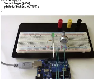
You are going to build a very simple circuit first, and then you will program it using your Arduino IDE. You will need your Arduino board, a breadboard, an LED, a 220-ohm resistor, a potentiometer, and some wires to build this example.
Breadboard
When working with electronics, it is often useful to “sketch” the circuit quickly so you can test it before building it in a more permanent form. Using a solderless breadboard, you can easily prototype
CHAPTER 1 ARDUINO BASICS
16
Figure 1-12. Bredboard connection diagram
Figure 1-13. Project sketched on a breadboard
Note that the pins flanked by blue and red lines on your breadboard (the top two rows and the bottom two rows in Figure 1-13) are connected together horizontally, so you can use them to provide 5V and ground to all the elements on the project. The other pins are connected in vertical strips broken in the middle. You use these linked strips to connect the resistor to the LED and the potentiometer pins to 5V, ground, and the Arduino Analog Input Pin 0.
Building the Circuit
CHAPTER 1 ARDUINO BASICS
The goal of this project is to control the brightness of the LED by turning the potentiometer. A potentiometer is basically a variable resistor that you control by turning the knob. Note that the
potentiometer is not connected to the LED or the resistor at all; it’s just connected to the Arduino board. You acquire the values coming from the potentiometer from Arduino and use these values to drive the brightness of the LED. All of this is done in the Arduino code.
Programming the Arduino
Now you are going to write the code that will permit you to drive the LED by turning your potentiometer. You will use serial communication to check the values that you are getting from the potentiometer in runtime using the Serial Monitor.
First, you declare a global integer variable called ledPin that defines the LED pin number during the execution of the program.
int ledPin = 11;
The setup() Function
After this, you write the setup() function in which you start serial communication at a baud rate of 9600 and define the pinMode of your LED pin to OUTPUT so you can write to it.
void setup() { Serial.begin(9600); pinMode(ledPin, OUTPUT); }
CHAPTER 1 ARDUINO BASICS
18
The loop() Function
In the loop() function, the first thing you do is declare a new local integer variable called sensorValue to store the value of the potentiometer connected to analog pin 0. You initialize the variable to this value by using the analogRead() function and specifying A0 (Analog 0) as your pin. If you were to read analog pin 1, you would write A1, and so on.
Then you print the value from the potentiometer to the serial buffer using the function
Serial.println(). If you open the Serial Monitor while the program is running, you will see that the values coming from the potentiometer range from 0 to 1023.
You want to use this value to set the brightness of your LED, but you have stated that the scope of the brightness needs to be in a range of 0 to 255. The solution to this issue will be mapping the values of the potentiometer from its range to the range of the potentiometer. You will use this technique very often in your projects; luckily, Arduino has a function to perform this operation called map().
The map() function takes five arguments: map(value, fromLow, fromHigh, toLow, toHigh). The argument value is the current value to be mapped. fromLow and fromHigh define the lower and higher values of the source range, and toLow and toHigh, the lower and higher values of the target range.
In your case, your LED brightness needs to be defined as map(sensorValue,0,1023,0,255), so if the sensor value is 1023, the LED brightness is 255. The map() function will always return an integer, even in the case that the mapping would result in a floating point number.
Once you have determined the brightness of the LED, you write this value to the LED pin using the function analogWrite(pin, value).
void loop() {
int sensorValue = analogRead(A0); Serial.println(sensorValue);
int ledBrightness = map(sensorValue,0,1023,0,255); analogWrite(ledPin, ledBrightness);
}
Upload this program to your Arduino board, and you will be able to change the brightness of your LED by turning the potentiometer. You will develop more advanced control techniques in Chapter 4, but before you move on, let’s go through some basic concepts on electronics.
Circuit Diagrams
We just described the circuit using photos and text. But when we get to more complicated circuits, this will not be enough. The way circuits should be represented is with circuit diagrams, or schematics.
Circuit diagrams show the components of a circuit as simplified standard symbols and the connections between the devices. Note that the arrangement of the elements on a diagram doesn’t necessarily correspond to the physical arrangement of the components.
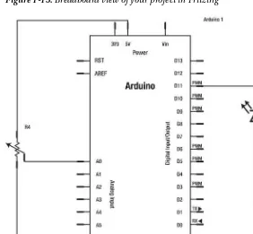
There are numerous software packages that facilitate the drawing of schematics, but there is one designed to be used by non-engineers, and it works nicely with Arduino projects: Fritzing.
Fritzing
Fritzing is an open source tool developed at the University of Applied Sciences of Potsdam in Germany; it’s aimed at artists and designers who want to develop their prototypes into real projects. You can (and should) download Fritzing from http://fritzing.org.
Fritzing has a graphical interface that allows the user to build the circuit as in the physical world, connecting together breadboards, Arduinos, LEDs, resistors, etc. Then you turn this visual
CHAPTER 1 ARDUINO BASICS
Figure 1-15. Breadboard view of your project in Fritzing
CHAPTER 1 ARDUINO BASICS
20
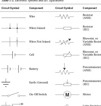
Electronic Symbols
Electronic symbols, or circuit symbols, are the pictograms used to represent electrical components and devices in the schematics. There are several international standards for these graphical symbols. In this book, we will use ANSI in all the circuit diagrams and symbols. Table 1-3 is a list of some electronics symbols that you will see used in this book and some of the IEC equivalents for reference.
Table 1-3. Electronic Symbols and IEC Equivalents
Circuit Symbol Component Circuit Symbol Component
Wire Resistor
(ANSI)
Wires Joined Resistor (IEC)
Wires Not Joined
Rheostat, or Variable Resistor (ANSI)
Cell
Rheostat, or Variable Resistor (IEC)
Battery Potentiometer (ANSI)
Earth (Ground) Potentiometer (IEC)
On-Off Switch Motor
NO COM NC
Relay Light Emitting
Diode (LED)
Electricity
CHAPTER 1 ARDUINO BASICS
AC/DC
Mains electricity is alternating current (AC), but you will be using direct current (DC) for all your
projects. AC is actually cheaper to produce and transmit from the power plants to your home. That is the reason why all the plugs in our households give us alternating current. But AC is also more difficult to control, so most electronic devices work with a power supply that converts AC into DC.
The current provided by your USB is DC, as is the current you get from a battery or a computer power supply, so you won’t work with AC at all in this book. Every time we speak about electricity or current in the book, we are referring to DC.
Ohms Law
Electricity, or electrical current is, very generally, the movement of electrons through a conductor. The intensity (I) of this current is measured in amperes (A).
The force pushing the electrons to flow is called voltage, which is the measure of the potential energy difference relative between the two ends of the circuit. Voltage is measured in Volts, or V.
The conductor through which the electrons are flowing will oppose some resistance to their passage. This force is called resistance, and it is measured in ohms (Ω).
Georg Ohm published a treatise in 1827 describing measurements of voltage and current flowing through circuits. Today, one of these equations has become known as Ohm’s law, and it ties together voltage, current, and resistance.
I
=
V
R
Putting this into words, the equation states that the current flowing through a conductor (I) is directly proportional to the potential difference (V) across the two ends. The constant of proportionality is called resistance (R).
Resistance is then the measure of the opposition to the passage of an electric current through an element. The opposite of resistance is conductance (G).
R
=
V
Ohm’s law can be rewritten in three different ways depending on which elements of the equation you already know and which one you are trying to calculate.
I
=
V
Joule’s first law, also known as Joule Effect, was declared by James Prescott Joule in the 1840s. This law states that the power dissipated in a resistor, in terms of the current through it and its resistance, is
P
=
I
2⋅
R
CHAPTER 1 ARDUINO BASICS
22
P
=
I
⋅
V
This helps you to choose the correct power rating for elements such as resistors and to calculate the power consumption from battery-driven supplies. This, in turns, lets you estimate how long your project will run on a set of batteries.
Summary
This first chapter has taken you through an overview of the Arduino platform in which both the Arduino hardware and software have been thoroughly analyzed.
Your Arduino board should be properly configured now, the Arduino IDE should be installed on your computer, and you should be communicating seamlessly with your board via USB. You have had a brief refresher course on basic electrical concepts, and you have warmed up with a couple of examples.
This introduction doesn’t intend to be a substitute for more introductory works. If this is your first contact with Arduino, you might want to consider having a look at some other titles like Beginning Arduino (Apress, 2010) before you go deeper into this book, or at least have one at hand just in case.
C H A P T E R 2
Kinect Basics
by Enrique Ramos
The Kinect, shown in Figure 2-1, was launched on November 4, 2010 and sold an impressive 8 million units in the first 60 days, entering the Guinness World Records as the “fastest selling consumer electronics device in history.” The Kinect was the first commercial sensor device to allow the user to interact with a console through a natural user interface (using gestures and spoken commands instead of a game controller). The Kinect is the second pillar of this book, so we will spend this chapter getting you acquainted with it.
In the following pages, you will learn the story of this groundbreaking device, its hardware, software, and data streams. You will learn what a structured-light 3D scanner is and how it is implemented in the Kinect sensor. You will learn about the different data you can acquire from your Kinect (such as RGB, infrared, and depth images), and how they are combined to perform motion tracking and gesture recognition. Welcome to the world of Kinect!
CHAPTER 2 KINECT BASICS
24
BUYING A KINECT
There are currently three ways to buy a Kinect sensor.
If you purchase the new Kinect for Windows or the Kinect for Xbox 360 as a standalone peripheral, both are ready to connect to your computer.
But maybe you already have a Kinect device that you are using with your Xbox 360, or you are planning to buy the Kinect together with an Xbox 360. If you purchase the Kinect bundled with the Xbox 360, you will also need to buy a separate power supply ($34.99 from Microsoft).
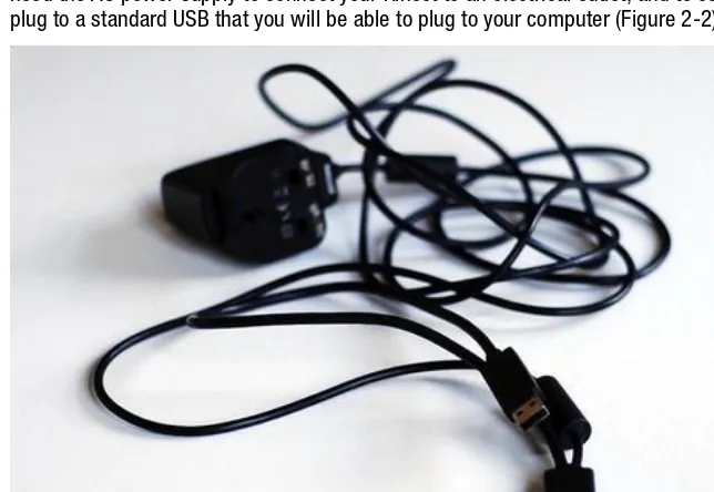
When used with the latest Xbox, the Kinect device doesn’t need the AC adapter, because the console has a special USB port that delivers enough power for the Kinect to function. Your computer USB can’t deliver as much current, though, and the special USB from Kinect doesn’t fit into your standard USB port. You will need the AC power supply to connect your Kinect to an electrical outlet, and to convert the special USB plug to a standard USB that you will be able to plug to your computer (Figure 2-2).
Figure 2-2. Kinect AC adapter with standard USB connection • Kinect for Windows ($249.99)
• Kinect for Xbox 360 as a standalone peripheral to be used with your previously purchased Xbox 360 ($129.99)
CHAPTER 2 KINECT BASICS
A Brief History of the Kinect
Microsoft announced the Kinect project on June 1, 2009 under the code name Project Natal. The name was changed to Kinect on June 13, 2010; it is derived from the words “kinetic” and “connect” to express the ideas behind the device. The motto of the marketing campaign for the launch was, very
appropriately, “You are the controller.”
This first launch caused a worldwide frenzy, and hackers soon found the one “open door” in this amazing device. Unlike other game controllers, the Kinect connection was an open USB port, so it could potentially be connected to a PC. Unfortunately, Microsoft had not released any PC drivers for the device and didn’t seem to be willing to do so in the near future.
Note Drivers are computer programs that allow other higher-level computer programs to interact with
hardware devices. They convert a well-known and predictable API (application programming interface) to the native API built into the hardware, making different devices look and behave similarly. Think of drivers as the translators between the hardware and the application or the operating system using it. Without the proper drivers, the computer wouldn’t know how to communicate with any of the hardware plugged into it!
Hacking the Kinect
Right after the Kinect was released in November 2010, and taking advantage of the Kinect’s open USB connection, Adafruit Industries offered a bounty of $1,000 to anybody who would provide “open source drivers for this cool USB device. The drivers and/or application can run on any operating system—but completely documented and under an open source license.” After some initial negative comments from Microsoft, Adafruit added another $2,000 to the bounty to spice it up.
The winner of the $3,000 bounty was Héctor Martín, who produced Linux drivers that allowed the use of both the RGB camera and the depth image from the Kinect.
The release of the open source drivers stirred a frenzy of Kinect application development that caught the attention of the media. Web sites dedicated to the new world of Kinect applications, such as http://www.kinecthacks.com, mushroomed on the Internet. The amazed public could see a growing number of new applications appear from every corner of the world.
Official Frameworks
But the Kinect hackers were not the only ones to realize the incredible possibilities that the new technology was about to unleash. The companies involved in the design of the Kinect soon understood that the Kinect for Xbox 360 was only a timid first step toward a new technological revolution—and they had no intention of being left behind.
In 2010, PrimeSense (the company behind Kinect’s 3D imaging) released its own drivers and programming framework for the Kinect, called OpenNI. Soon after that, it announced a partnership with ASUS in producing a new Kinect-like device, the Xtion.
In 2011, Microsoft released the non-commercial Kinect SDK (software development kit). In February 2012, it released a commercial version, accompanied by the Kinect for Windows device.
CHAPTER 2 KINECT BASICS
26
The Kinect Sensor
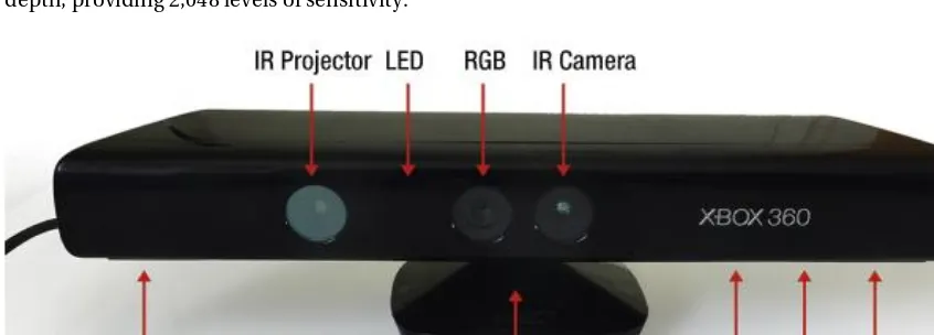
The Kinect sensor features an RGB camera, a depth sensor consisting of an infrared laser projector and an infrared CMOS sensor, and a multi-array microphone enabling acoustic source localization and ambient noise suppression. It also contains an LED light, a three-axis accelerometer, and a small servo controlling the tilt of the device.
Note The infrared CMOS (complementary metal–oxide semiconductor) sensor is an integrated circuit that contains an array of photodetectors that act as an infrared image sensor. This device is also referred to as IR camera, IR sensor, depth image CMOS, or CMOS sensor, depending on the source.
Throughout this book we will focus on the 3D scanning capabilities of the Kinect device accessed through OpenNI/NITE. We won’t be talking about the microphones, the in-built accelerometer, or the servo, which are not accessible from OpenNI because they are not part of PrimeSense’s reference design.
The RGB camera is an 8-bit VGA resolution (640 x 480 pixels) camera. This might not sound very impressive, but you need to remember that the magic happens in the depth sensor, which is completely independent of the RGB camera.
The two depth sensor elements, the IR projector and IR camera, work together with the internal chip from PrimeSense to reconstitute a 3D motion capture of the scene in front of the Kinect (Figures 2-3 and 2-4). They do this by using a technique called structured-light 3D scanning, which we will discuss in depth at the end of this chapter. The IR camera also uses a VGA resolution (640 x 480 pixels) with 11-bit depth, providing 2,048 levels of sensitivity.
CHAPTER 2 KINECT BASICS
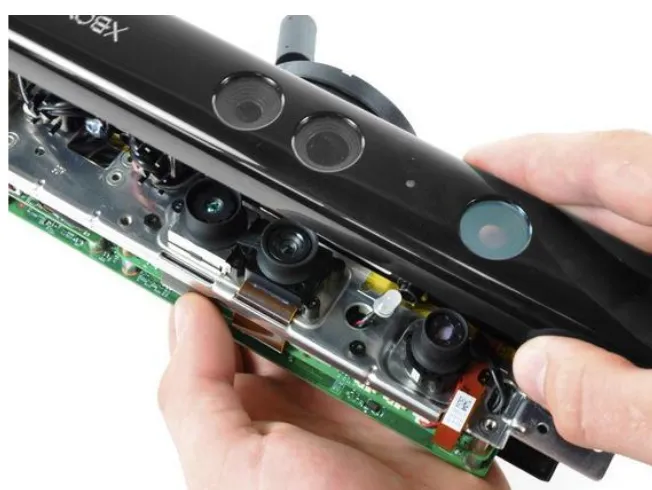
Figure 2-4. Left to right: Kinect IR camera, RGB camera, LED, and IR projector (photo courtesy of ifixit)
Of course, there is much more going on within the sensor. If you are interested in the guts of the Kinect device, the web site ifixit featured a teardown of the Kinect in November 2010
(http://www.ifixit.com/Teardown/Microsoft-Kinect-Teardown/4066).
Positioning your Kinect
The Kinect’s practical range goes from 1.2m to 3.5m. If the objects stand too close to the sensor, they will not be scanned and will just appear as black spots; if they are too far, the scanning precision will be too low, making them appear as flat objects. If you are using the Kinect for Windows device, the range of the camera is shorter, from 40cm to 3m.
Kinect Capabilities
So what can you do with your Kinect device and all of the hi-tech stuff hidden inside? Once the Kinect is properly installed and communicating with your computer, you will be able to access a series of raw data streams and other capabilities provided by specific middleware. In this book, we will use the OpenNI drivers and NITE middleware.
RGB Image
CHAPTER 2 KINECT BASICS
28
IR Image
As Kinect has an infrared CMOS, you can also access the 640 x 480 IR image using OpenNI. This is also covered in Chapter 3.
Depth Map
The depth map is the result of the operations performed by PrimeSense’s PS1080 chip on the IR image captured by Kinect’s IR CMOS. This VGA image has a precision of 11 bits, or 2048 different values, represented graphically by levels of grey from white (2048) to black (0).
In Chapter 3, you will learn how to access and display the depth image from Processing using the OpenNI framework and how to translate the gray scale image into real space dimensions. There is one detail that you should take into consideration: the sensor’s distance measurement doesn’t follow a linear scale but a logarithmic scale. Without getting into what a logarithmic scale is, you should know that the precision of the depth sensing is lower on objects further from the Kinect sensor.
Hand and Skeleton Tracking
After the depth map has been generated, you can use it directly for your applications or run it through a specific middleware to extract more complex information from the raw depth map.
In the following chapters, you will be using NITE middleware to add hand/skeleton tracking and gesture recognition to your applications. Chapter 4 will teach you how to use hand tracking to control LED lights through an Arduino board. Chapter 5 will introduce NITE’s gesture recognition, and you will even program your own simple gesture recognition routine. Chapter 6 will teach you how to work with skeleton tracking.
The algorithms that NITE or other middleware use to extract this information from the depth map fall way beyond the scope of this book, but if you are curious, you can read Hacking the Kinect by Jeff Kramer et al (Apress, 2012), in which you will find a whole chapter on gesture recognition.
Kinect Drivers and Frameworks
In order to access the Kinect data streams, you will need to install the necessary drivers on your computer. Because of the rather complicate story of this device, there are a series of choices available that we will detail next.
OpenKinect: Libfreenect Drivers
CHAPTER 2 KINECT BASICS
PrimeSense: OpenNI and NITE
Throughout this book, we will be using OpenNI and NITE to access the Kinect data streams and the skeleton/hand tracking capabilities, so here is a little more detail on this framework. The Israeli company PrimeSense developed the technology behind Kinect’s 3D imaging and worked with Microsoft in the development of the Kinect device. In December 2010, PrimeSense created an industry-led, not-for-profit organization called OpenNI, which stands for open natural interaction (http://www.openni.org).
This organization was formed to “certify and promote the compatibility and interoperability of natural interaction (NI) devices, applications, and middleware.” The founding members of the OpenNI organization are PrimeSense, Willow Garage, Side-Kick, ASUS, and AppSide.
OpenNI
In order to fulfill its goal, OpenNI released an open source framework called OpenNI Framework. It provides an API and high-level middleware called NITE for implementing hand/skeleton tracking and gesture recognition.
Figure 2-5. OpenNI abstract layered view (courtesy of PrimeSense)
CHAPTER 2 KINECT BASICS
30
Kinect was the first implementation of the PrimeSense reference design; its optics and microchip were developed entirely by PrimeSense. Then Microsoft added a motor and a three-axis accelerometer to the design. This is why OpenNI doesn’t provide access to the motor or the accelerometer; they are specific to the Kinect implementation.
PrimeSense is a fabless (fabrication-less) semiconductor company. It makes its revenue by selling hardware and semiconductor chips while outsourcing fabrication. It’s mainly a B2B (business to business): it sells solutions to manufacturers who insert these solutions into consumer products. This is exactly the way in which it was involved in the development of the Kinect with Microsoft.
PrimeSense then sells its technology to manufacturers such as ASUS and other computer or television manufacturers. But for this market to be developed, there needs to exist an ecosystem of people creating natural interaction-based content and applications. PrimeSense created OpenNI as a way to empower developers to add natural interaction to their software and applications so this ecosystem would flourish.
NITE
For natural interaction to be implemented, the developer needs more than the 3D point cloud from Kinect. The most useful features come from the skeleton and hand tracking capabilities. Not all developers have the knowledge, time, or resources to develop these capabilities from scratch, as they involve advanced algorithms. PrimeSense decided to implement these capabilities and distribute them for commercial purposes but keep the code closed, and so NITE was developed.
Note There has been much confusion about the differences between OpenNI and NITE. OpenNI is PrimeSense’s framework; it allows you to acquire the depth and RGB images from the Kinect. OpenNI is open source and for commercial use. NITE is the middleware that allows you to perform hand/skeleton tracking and gesture recognition. NITE is not open source, but it is also distributed for commercial use.
This means that without NITE you can’t use skeleton/hand tracking or gesture recognition, unless you develop your own middleware that processes the OpenNI point cloud data and extracts the joint and gesture information. Without a doubt, there will be other middleware developed by third parties in the future that will compete with OpenNI and NITE for natural interaction applications.
In Chapter 3, you will learn how to download OpenNI and NITE, and you will start using them to develop amazing projects throughout the rest of the book.
Microsoft Kinect for Windows
On June 16, 2011, six months after PrimeSense released its drivers and middleware, Microsoft announced the release of the official Microsoft Kinect SDK for non-commercial use. This SDK offered the programmer access to all the Kinect sensor capabilities plus hand/skeleton tracking. At the time of writing, Kinect for Windows SDK includes the following:
• Drivers for using Kinect sensor devices on a computer running Windows 7 or Windows 8 developer preview (desktop apps only)
• APIs and device interfaces, along with technical documentation
CHAPTER 2 KINECT BASICS
Unfortunately, the non-commercial license limited the applications to testing or personal use. Also, the SDK only installs on Windows 7, leaving out the Linux and Mac OSX programmer communities. Moreover, the development of applications is limited to C++, C#, or Visual Basic using Microsoft Visual Studio 2010.
These limitations discouraged many developers, who chose to continue to develop applications with OpenNI/NITE plus their OS and developing platform of choice, with an eye towards the commercialization of their applications.
From February 2012, the Kinect for Windows includes a new sensor device specifically designed for use with a Windows-based PC and a new version of the SDK for commercial use. The official Microsoft SDK will continue to support the Kinect for Xbox 360 as a development device.
Kinect Theory
The technique used by PrimeSense’s 3D imaging system in the Kinect is called structured-light 3D scanning. This technique is used in many industrial applications, such as production control and volume measurement, and involves highly accurate and expensive scanners. Kinect is the first device to implement this technique in a consumer product.
Structured-Light 3D Scanning
Most structured-light scanners are based on the projection of a narrow stripe of light onto a 3D object, using the deformation of the stripe when seen from a point of view different from the source to measure the distance from each point to the camera and thus reconstitute the 3D volume. This method can be extended to the projection of many stripes of light at the same time, which provides a high number of samples simultaneously (Figure 2-6).
Figure 2-6. Triangulation principles for structured-light 3D scanning (from Wikipedia,
CHAPTER 2 KINECT BASICS
32
The Kinect system is somewhat different. Instead of projecting stripes of visible light, the Kinect’s IR projector sends out a pattern of infrared light beams (called an IR coding image by PrimeSense), which bounces on the objects and is captured by the standard CMOS image sensor (see Figure 2-7). This captured image is passed on to the onboard PrimeSense chip to be translated into the depth image (Figure 2-8).
Figure 2-7. Kinnect IR coding image (detail)
CHAPTER 2 KINECT BASICS
Converting the Light Coding Image to a Depth Map
Once the light coding infrared pattern is received, PrimeSense’s PS1080 chip (Figure 2-9) compares that image to a reference image stored in the chip’s memory as the result of a calibration routine performed on each device during the production process. The comparison of the “flat” reference image and the incoming infrared pattern is translated by the chip into a VGA-sized depth image of the scene that you can access through the OpenNI API.
Figure 2-9. PrimeSense PS1080 system on chip (image courtesy of PrimeSense)
Kinect Alternative: ASUS Xtion PRO
CHAPTER 2 KINECT BASICS
34
Note ASUS Xtion is OpenNI- and NITE-compatible, which means that all the projects in this book can also be implemented using an Xtion PRO LIVE camera from ASUS!
Figure 2-10. ASUS Xtion PRO LIVE (image courtesy of ASUS)
Summary
This chapter provided an overview of the Kinect device: its history and capabilities, as well as its hardware, software, and the technical details behind its 3D scanning. It was not the intention of the authors to give you a detailed introduction to all of the technical aspects of the Kinect device; we just wanted to get you acquainted with the amazing sensor that will allow you to build all the projects in this book—and the ones that you will imagine afterwards.
C H A P T E R 3
Processing
by Enrique Ramos
This book is about making projects with Kinect and Arduino, and one of the most direct ways of
interfacing them is through Processing, a Java-based, open source programming language and IDE. You should be familiar with Arduino by now, so you will be glad to know that the Processing IDE much resembles Arduino’s. In fact, the Arduino IDE was based on the Processing IDE (see Figure 3-1).
CHAPTER 3 PROCESSING
36
One of the best features of Processing is that, being built on Java, there is a vast community of people creating Processing libraries that you can use for your projects without having to worry (too much) about the scary, dark places hidden behind every class and method. Kinect is no exception to this, and thus Processing is able to talk to Kinect devices through several libraries available from its web site. Processing is also capable of talking to Arduino using serial communication.
This chapter will get you acquainted with the basics of the Processing language and Simple-OpenNI, one of Processing’s Kinect libraries. Throughout the rest of the book, you will be creating Kinect and Arduino projects that talk through Processing and Simple-OpenNI, so the understanding of these techniques is essential to the development of any of the upcoming projects.
Processing Language
Casey Reas and Ben Fry, both formerly of the Aesthetics and Computation Group at the MIT Media Lab, created Processing in 2001 while studying under John Maeda. One of the stated aims of Processing is to act as a tool to get non-programmers started with programming. On the Processing web site
(http://www.processing.org), you can read this introduction:
Processing is an open source programming language and environment for people who want to create images, animations, and interactions. Initially developed to serve as a software sketchbook and to teach fundamentals of computer programming within a visual context, Processing also has evolved into a tool for generating finished professional work. Today, there are tens of thousands of students, artists, designers, researchers, and hobbyists who use Processing for learning, prototyping, and production.
Processing is based in Java, one of the most widespread programming languages available today. Java is an object-oriented, multi-platform programming language. The code you write in Java is
compiled into something called bytecode that is then executed by the Java Virtual Machine living in your computer. This allows the programmer (you) to write software without having to worry about the operating system (OS) it will be run on. As you can guess, this is a huge advantage when you are trying to write software to be used in different machines.
Processing programs are called sketches because Processing was first designed as a tool for designers to quickly code ideas that would later be developed in other programming languages. As the project developed, though, Processing expanded its capabilities, and it is now used for many complex projects as well as a sketching tool.
We won’t have space in this book to discuss the ins and outs of the Processing language, but if you are familiar with Java, C++, or C#, you will have no problem following the code in this book. For a thorough introduction to Processing, I strongly recommend Ira Greenberg’s monumental Processing: Creative Coding and Computational Art.
Installing Processing
Installing Processing is definitely not much of a hassle. Go to http://www.processing.org and download the appropriate version for your OS of choice. If you are a Windows user and you aren’t sure if you should download the Windows or Windows without Java version, go for the Windows version. The other version will require you to install the Java Development Kit (JDK) separately. Once you have downloaded the .zip file, uncompress it; you should find a runnable file. If you run it, you should get a window like the one depicted in Figure 3-2.
CHAPTER 3 PROCESSING
Figure 3-2. Processing IDE
Processing IDE
As mentioned, the Processing IDE is very similar to the Arduino IDE described in Chapter 2. There is a console at the bottom of the Processing IDE; a message area that will warn you about errors in the code and at runtime; a text editor where you will write your code; plus a tab manager and a toolbar at the top of the IDE.
The Processing toolbar has a distribution of buttons similar to Arduino, yet with some differences (see Figure 3-2). The New, Open, and Save buttons play the same roles as in Arduino. But instead of having Verify and Upload buttons at the left, there are Run and Stop buttons. You might have guessed what they are for, but just in case, the Run button will run your application and the Stop button will halt it. There is another button called Export PApplet; pressing it will convert the Processing code into Java code and then compile it as a Java Applet, which can be embedded in a web browser. This is the way you’ll find Processing Applets, or PApplets, displayed on the Internet.
CHAPTER 3 PROCESSING
38
A First Processing Sketch
Processing was designed for simplicity, and it allows you to create runnable programs with just a few lines of code. Your first Processing sketch will get you acquainted with the basic structure on a Processing program. But first, let’s get into some general programming concepts.
Processing Variables
Variables are symbolic names used to store information in a program. There are eight primitive data types in Java, and they are all supported in Processing: byte, short, int, long, float, double, boolean, and
char. A detailed explanation of each one of these data types would be beyond the scope of this book, but we will state some general rules.
Integers (int) will be used to store positive and negative whole numbers (this means numbers without a decimal point, like 42, 0, and 56. An integer variable can store values ranging from
-2,147,483,648 to 2,147,483,647 (inclusive). If you need to store larger numbers, you need to define your variable as a long.
Whenever you need more precision, you will be using floating-point numbers, or floats, which are numbers with a decimal place (23.12, 0.567, -234.63). The data type double works the same way as float, but it is more precise. In general, Processing encourages the use of floats over doubles because of the savings in memory and computational time.
The data type boolean stores two values: true and false. It is common to use booleans in control statements to determine the flow of the program.
The character data type, or char, stores typographic symbols (a, U, $). You will use this data type when you want to display or work with text.
Even though String is not a proper Java primitive, we are going to discuss it here, as you will be using it to store sequences of characters. String is actually a class (more about this in Chapter 4), with methods for examining individual characters, comparing and searching strings, and a series of other tools that you will use to work with text and symbols in your programs.
Variable Scope
Whenever you declare a variable, you are implicitly setting a scope, or realm of validity for the variable. If you declare the variable within a function, you will be able to access it only from within that specific function. If you define the variable outside of any function, the variable will be set as a global variable and every function in the program will be allowed to “see” and interact with the new variable.
Structure of a Processing Sketch
Open your Processing IDE and declare a timer integer variable outside of any function. As mentioned, variables defined like this are treated as global variables in Processing, so you can call them from any method and subclass.
int timer;
setup() Function
CHAPTER 3 PROCESSING
void setup(){ size(800,600); }
You can include comments in your code as a means to remind yourself—or inform anybody else reading your code—about specific details of the code. There are two main types of comments: single line comments, which start with two forward slash characters, and multi-line comments, used for large descriptions of the code. You can include some comments in your setup() function in the following way:
void setup(){
// The next function sets the size of the sketch size(800,600);
/*
This is a multiline comment, anything written between the two multiline commment delimiters will be ignored by the compiler.
*/ }
There is a third kind of comment, the doc comment (/** comment */), which can be used to
automatically generate Javadocs for your code. You won’t be using this sort of comment in this book, but they can be extremely useful when writing programs intended to be used by other people.
draw() Function
Next, you need to include a draw() function that will run as a loop until the program is terminated by the user. You are going to draw a circle on screen that will move to the right of the screen as time passes. Remember to include a background() function to clear the frame with a color at every iteration. If you comment it out (temporarily remove it by adding // to the beginning of the line), you will see that the circles are drawn on top of the previous ones.
void draw() { background(255);
ellipse(timer, height/2, 30, 30); timer = timer + 1;
}
Now you are ready to run your sketch. Press the Run button at the top-left of your Processing IDE (marked with a red arrow in Figure 3-3) and you will see a new window open with a white circle running to the right side.
CHAPTER 3 PROCESSING
40
Figure 3-3. Your first Processing sketch
Processing Libraries
Processing libraries are lines of Java code that have been packaged into a .jar file and placed in the libraries folder in your system so you can call its functions from any Processing sketch. There are two sorts of libraries: core libraries, like OpenGL and Serial, which are included with Processing when you download it, and contributed libraries, which are created and maintained by members of the Processing community. Contributed libraries need to be downloaded and stored in the libraries folder in your system. If you are a Mac OS X user and you have saved the Processing application in the Applications folder, the path will be the following:
/Applications/Processing/Contents/Resources/Java/modes/java/libraries
To open your Processing application on Mac OS X (it is essentially a folder, so to find the libraries folder), right-click the icon and select “Show Package Contents” from the pop-up menu.
If you are working on a Windows machine and you have put the Processing folder in the Program Files folder, this will be your path: