Beginning Analog
Electronics Through
Projects
Beginning Analog
Electronics Through
Projects
Second Edition
Andrew Singmin
Copyright © 2001 by Butterworth–Heinemann
A member of the Reed Elsevier group
All rights reserved.
No part of this publication may be reproduced, stored in a retrieval system, or transmitted in any form or by any means, electronic, mechanical, photocopying, recording, or otherwise, without the prior written permission of the publisher.
Recognizing the importance of preserving what has been written, Butterworth–Heinemann prints its books on acid-free paper whenever possible.
Butterworth-Heinemann supports the efforts of American Forests and the Global ReLeaf program in its campaign for the betterment of trees, forests, and our environment.
Library of Congress Cataloging-in-Publication Data Singmin, Andrew, 1945–
Beginning analog electronics through projects / Andrew Singmin.—2nd ed. p. cm.
New ed. of: Beginning electronics through projects / Andrew Singmin. c1997. Includes index.
ISBN 0-7506-7283-8 (pbk. : alk. paper)
1. Electronics—Amateurs’ manuals. 2. Analog electronic systems—Amateurs’ manuals.
I. Singmin, Andrew, 1945– Beginning electronics through projects. II. Title. TK9965 .S544 2000
621.381—dc21 00-063805
British Library Cataloguing-in-Publication Data
A catalogue record for this book is available from the British Library. The publisher offers special discounts on bulk orders of this book. For information, please contact:
Manager of Special Sales Butterworth–Heinemann 225 Wildwood Avenue Woburn, MA 01801-2041 Tel: 781-904-2500 Fax: 781-904-2620
For information on all Newnes publications available, contact our World Wide Web home page at: http://www.newnespress.com
10 9 8 7 6 5 4 3 2 1
Contents
Preface ix
Introduction xi
1
Overview of Analog and Digital
Electronics
1
2
Resistors
7
3
Potentiometers
11
4
Multimeters
13
5
Ohm’s Law
15
6
Light-Emitting Diodes
17
7
Switches
19
8
Capacitors
21
9
Integrated Circuits
23
10 Tools
25
11 Soldering
27
12 Basic Electronics Theory
29
14 Assembly Techniques
33
15 Handling Components
37
16 The SINGMIN PCB Circuit Assembly
Board
39
17 Construction Details for 10 Simple
Projects
43
Project #1: Fixed Low-Frequency LED Flasher 43
Project #2: Variable Low-Frequency LED Flasher/Driver 52 Project #3: Fixed Low-Gain Audio Power Amplifier 59 Project #4: Fixed-Frequency Audio Tone Generator 65 Project #5: Variable-Gain Audio Power Amplifier 71 Project #6: Fixed-Gain Audio Preamplifier 77 Project #7: Guitar Headphone Amplifier 83 Project #8: Visual Electronic Metronome 89
Project #9: Variable-Gain, Hi/Lo Response Audio Preamplifier 94 Project #10: Dual-Gain Electret Microphone Audio
Preamplifier 101
18 Troubleshooting Test Equipment
109
Project #11: Signal Injector 109Project #12: Signal Monitor 114
Preface
Much has transpired between the release of my first edition of Beginning Electronics Through Projects, published in 1997, and this second edition,
Beginning Analog Electronics Through Projects. For the most part, I’ve been busy developing several new books, including Practical Audio Amplifier Circuit ProjectsandBeginning Digital Electronics Through Projects. You’ll find many significant differences between the first edition of this book and the current edition, many of which you’ll need to know to proceed with the projects. Please refer to the introduction for a list of the key changes.
There will no doubt always be a succession of new-generation enthusiasts embarking on their first introduction to electronics (be it for fun or work), and on the lookout for easy-to-understand introductory books on the subject. For those beginner enthusiasts and hobbyists, my books are suited to your needs.
Have fun building the projects and, at the same time, increasing your working knowledge of electronics.
I had fun working with you, Candy!
Introduction
This book is divided into two main sections: The first part (Chapters 1 through 16) covers some of the basic descriptions and theory of electronic components, and the second part (Chapters 17 and 18) provides detailed instructions for constructing 12 simple electronic projects. The initial section deals exclusively with only the types of components that are later used in the projects.
The beginner in electronics is often handicapped by exposure to far too many subject areas, even at the elementary level. Thus textbooks traditionally have the habit, in the interest of completeness, of covering so many subject topics that, more often than not, the beginner is left confused. I speak from experience, remembering my own start in electronics!
This book, therefore, takes a different approach in that only the compo-nents and theory that are of use and relevance to the chapter on project con-struction will be covered. The aim here is to make the beginner comfortable with a limited range of components and circuit theory, rather than confused over a wider range of topics.
The emphasis in this book is focused on the practical aspects of electron-ics. Through the construction of the projects and a developed understanding of the theory behind the components and techniques, I hope you will gain a better appreciation of the subject and perhaps be encouraged to pursue electronics even further. When I started in electronics as a hobby, I experienced the tremendous shortage of good, practical books on the subject. Those few that were available were either too theoretical (most of them), described circuits that had components that were impossible to obtain, or were far too difficult to understand, let alone build. Many beginners take on projects that are far too complex and become discouraged when the circuit fails to work; however, by focusing here on simpler circuits to begin with, the chances of success are much higher, especially in view of the abundance of clear instructions given.
construction projects. It will be extremely beneficial for you to work through these early chapters carefully, making sure you understand things as you progress. No matter how complex electronic circuits are, they can always be broken down into simpler parts that are easier to understand. Although many more different components exist than the types listed here, from a beginner’s point of view we are limiting the description to just those components that you will encounter in the construction projects. We will go through just as much theory as is needed to cover the construction projects. In short, everything that follows is relevant.
Armed with this book, a collection of electronic components, and a hot soldering iron fired up and ready to go, you should be well on your way to the start of an exciting new hobby or even on the threshold of a new career!
Please note the following changes between the first edition of this book and the current edition before proceeding:
1. The projects in the first edition were designed to use a dedicated prototype board of my own design called the SINGMIN PCB. This board was developed in order to overcome the limitations found with existing assembly boards. When the first edition of this book was written, I used the SINGMIN PCB extensively for circuit builds, so the projects in that book showcased this unique design.
Several years have passed since then and my custom assembly platform is no longer available. It is not mandatory, however, to use this specific PCB, and you can use whatever alternate assembly boards suit your own preferences. Alternately, you can use the design of the SINGMIN PCB as an example template or layout guide to design your own boards, using whatever commercial assembly is available. The two extra projects in this second edition (#11 and #12) are left for you as an exercise in initiative—to do the board layout yourself. Here are some useful placement tips when either using a universal prototyping board or putting your own board design together.
• Assign a power rail running horizontally across the top of your board to be the positive voltage rail.
• Assign a ground rail running horizontally across the bottom of the board to be the negative (or ground) rail.
• Because power connections will likely be required at the bottom of the board, also assign a secondary power rail along the bottom of the board. This will be connected to the upper principal power rail.
• A similar premise applies to the ground rail, so add a secondary ground rail along the top of the board, and have it connected to the principal lower ground rail.
operated off a single (9-volt) supply. You will notice in all of my circuits of this type that several of these components are needed. These components (nominally two resistors and a capacitor) can consume a considerable amount of not only board space, but also valuable solder connections.
• Keep the component layout as close as possible to the schematic layout, so troubleshooting is simplified when you’re verifying wiring interconnection traces and component placements.
2. The project kits that were mentioned in the first edition of this book are no longer available. The components, however, are all readily available at your local electronics component store.
Now it’s time to begin with Chapter 1. If you like to work to music like me, put your favorite tape or CD on (for me, it’s the Dixie Chicks), turn up the volume, and let’s start building.
CHAPTER
1
Overview of
Analog and Digital
Electronics
Analog Electronics
Sooner or later you’ll ask, what’s the difference between analog and digital electronics? Analog circuits are conventionally where most beginners to electronics start because we can identify much more easily with analog con-cepts in electronics. Take, for example, the simplest and best analog scenario— audio amplifiers. Everyone is familiar with audio amplifiers in one form or another, from TV, stereo sound systems, cassette recorders, Walkmans, CD players, and so on. Audio is a concept we can readily identify with. You can be guaranteed that almost all people, at some point in their lives, have encoun-tered audio. If our ears pick up sound, we know it’s there (so to speak).
We can distinguish easily between clear, clean sounds and distorted sounds, low sound levels and high sound levels. Turn up the bass on your stereo system and everyone knows (you don’t have to be electronics-knowledgeable) what that sounds like. Jimi Hendrix’s screaming guitar work (perhaps not to everyone’s taste) is clearly different from a classical Mozart rendition. Once more, no electronics appreciation is needed to per-ceive the difference.
That’s why analog electronics is so satisfying to work with—we can see (well, actually hear) the results and appreciate the differences instantly. Video circuits, although still analog, are much more difficult to work with. There are no equivalent easy-to-use circuits as we have in the audio case, and even if there were, they would still not be the same clarity in being able to distinguish between different video characteristics. Video gets a little far removed from the user being able to distinguish differences. Why do I mention video here? Well, digital is still one more step removed than video and is, therefore (in my opinion), an even more faceless entity—and therefore a more difficult concept for the beginner to appreciate.
medical thermometer. The temperature reading changes smoothly; there is no jump from one level to another. Depending on the type of thermometer deployed, the incremental changes in temperature will be different, but it is always continuous. That’s one of the key properties of an analog signal—it’s continuously varying.
We (i.e., humans) are familiar with entities that change in this manner. Analog electronics is concerned with the processing of analog signals, which is usually amplification, filtering, or signal generation. And once more, the elec-tronic amplifier is the prime example of analog elecelec-tronics. Most beginners’ introduction to electronics (and it is usually analog electronics) is the encounter of the basic amplifier block. Amplifiers, by implication of the title, change a small signal into a larger signal.
Let’s say we monitor (by one means or another) the starting signal, pass it through an amplifier, and then look at the resultant signal; if it has increased in magnitude, then we know it’s been amplified. Anything from preamplifier circuits, which generally increase the voltage level (but not the current level) of the starting signal, to power amplifiers, which increase the drive (i.e., current) capacity of the signal, is included in this category. Preamplifiers, although increasing the signal amplitude, don’t have any capability to drive a low-impedance load, such as a speaker, and many applications (e.g., audio systems) have a final requirement of needing to do that.
Where we’re going to ultimately drive a speaker (this is a low-impedance load, meaning that the resistance of the load is low, typically less than 10 ohms), we’re going to consume significant current. From Ohm’s law we know that when a voltage is applied to a resistance, the resultant current flow increases in inverse proportion to the load resistance. A low load resistance draws more current, which in turn means that the power amplifier driving this load must be capable of supplying the load current. That’s the principal difference between a preamplifier (which is essentially a voltage amplifier) and a power amplifier (although it has some voltage gain, too), which is essentially a current-supplying (or power) amplifier.
Analog amplifier circuits are always characterized by having the input signal and output signal capacitively coupled. The presence of the capacitors removes the dc component of the signal, and passes only the ac component for processing (i.e., amplification in this case), since the information we’re inter-ested in is contained within the ac signal. Analog signals are typically sinu-soidal in form, which means that apart from the dimension of amplitude, they are also characterized by a dimension of frequency. Frequency is the measure of the number of complete cycles of the sine wave that occurs in one second, where the second is defined as the period of reference. A low-frequency audio signal, for example, could be 100 Hz, which means that over a 1-second dura-tion there are 100 complete cycles.
zero volts, down to a minimum, and back to zero again; this excursion is defined as one cycle. The waveform just repeats in time and is defined as a peri-odic waveform. This waveform can be easily seen by coupling it into an oscil-loscope, which is basically an instrument for monitoring periodic waveforms. A high-frequency signal (e.g., 10 kHz) would have more cycles contained in a 1-second reference measure—10,000 cycles to be exact. The reference measure (whatever it is) of course needs to be defined in order for a measure of the signal of interest to be made.
The most popular and commonly used analog circuit today is undoubt-edly the operational amplifier, which is most generally encountered in the inverting amplifying mode. Amplifier circuits are one of the most common cir-cuits seen in all of electronics because all electronic signals of interest, such as microphone signals or radio signals, are very weak (i.e., small in amplitude), and hence need to be amplified to a useful level. Using the operational ampli-fier as the basis of construction, it is extremely easy to design and build a stable circuit.
That’s the beauty of operational amplifier circuits—the circuit perfor-mance is predictable and unaffected, in the main by the operational amplifier itself. The operational amplifier gain is just determined by the ratio of two resistors. Contrast this with building up an amplifier from discrete circuits (transistors, resistors, and capacitors), where the circuit performance is going to be affected by the transistor characteristics and a mix of the circuit compo-nents used.
As your electronics expertise and enthusiasm grow through the practical learning process of learning by doing, you can move on to other circuit projects at a more intermediate, but still understandable, level. You’ll find these pro-jects in my publication titled Practical Audio Amplifier Circuit Projects, where there are 16 audio-based projects included, in addition to a wealth of more detailed information provided on audio amplifiers and audio-related circuits.
Because I find a lot of enjoyment running through blues riffs on a Fender Stratocaster, my emphasis is on electric guitar music projects. So that book’s highlight is a nice Guitar Pacer project, which allows you to jam alongside your favorite musician because this unit mixes in your own guitar work with the tape track of your guitar idol.
At this stage, too, you might also be looking for a dictionary of electron-ics terminology. Check out another one of my books,Dictionary of Modern Electronics Technology, where you’ll find a good cross-section of modern ter-minology used in electronics. I’ve included what I’ve found in all my years of electronics activity, both at work and for fun, and all the terms that I needed to find the definitions of.
Digital Electronics
signals) is no longer continuous, but discrete; that is, moving between two clearly defined levels, which are generally defined as the starting zero voltage point and a positive maximum. The digital signal is also periodic (like the analog sine wave), but instead of being an essentially smoothly moving contin-uous signal, it just goes from zero level to a positive maximum level and back to zero again. This is like a series of sharp quantum changes in signal ampli-tude. This sharp change can also be discerned in an audio sense.
If you were to listen to a digital square wave (which is what it’s com-monly known as), then the sound would be rough and harsh.The harshness can be thought of as being aligned with the quantum nature of the digital signal. On the other hand, the analog counterpart sounds smooth—an artifact that can be associated with the inherent continuum of the analog waveform’s property.
The same time reference measure (one second) is used in order to char-acterize the digital signal of interest. Digital signals are defined by repetition rate rather than by frequency, but it is essentially the same thing. A 1-kHz rep-etition rate digital signal has 1,000 cycles (defined in exactly the same way as the analog signal) per second, whereas a 10-kHz digital signal has 10,000 cycles contained in a 1-second measure. The oscilloscope can also provide a visual display of a digital signal because it is also a periodic signal (regardless of waveform shape).
Digital electronics are not involved with amplification or filtering of signals (as in the analog case), but rather concern issues such as counting pulses and triggering subsequent circuits when a number of predetermined pulses have been generated. A pulse is just a single digital signal going from a zero value, to a maximum, and returning to a zero value, as opposed to the alternate, which is a train of continuous pulses. The occurrence of a pulse event is based on detecting either the positive-going pulse edge (where the pulse goes from a zero voltage level to a positive maximum voltage level), which is the more usual case, or alternately, the negative-going edge (where the pulse goes from a maximum voltage to a zero voltage level) of the input digital signal.
There are two main types of digital circuits popularly in use: TTL digital and CMOS digital circuits. The first of these circuits, TTL (transistor transistor logic) technology, is characterized by having a power supply voltage that operates off 5 volts. This technology is the most commonly used digital type and can be found in most logic designs. Although the digital schematic is essentially transparent to the technology type used, the parts list will define the technology type. The second digital technology type in use is CMOS (comple-mentary metal oxide semiconductor) technology, which runs off a supply voltage range from 3 volts to 15 volts. But the main distinction between CMOS and TTL is the considerably lower power supply current requirements of CMOS. The consequent lower power consumption (for CMOS) translates to a longer, more desirable operating life (from battery-powered circuits). A con-tinuous drive toward a lower supply voltage means a more compact battery requirement.
I’ve found that digital electronics books for beginners tend to be less successful than their analog counterparts in making the presentation both interesting and informative, because of the more abstract nature of digital elec-tronics. Trying to get excited about binary digits and truth tables is not much to work with. So the approach I’ve taken, in my excursion to cover this topic, is to follow the same successful format I’ve used for my analog books, which is to focus on a learning-by-building approach. With the right approach, almost any topic learning task can be made fun.
Using project builds to learn has always been fun for me, so I’m guessing it’s going to be fun for you, too. My Beginning Digital Electronics Through Projectsbook has a central focus of learning by building digital-based circuits that are simple to follow, use readily available components, and limit the com-plexity to just a single integrated circuit. This is not to say that the circuits described have limited value—far from it. You don’t need a complex array of ICs for a circuit to be innovative and useful. This is a useful book to get a solid grounding in the world of digital electronics. For fun, there’s an FM transmit-ter circuit project that’s easy to build and fun to use. It’s RF and not digital, but it’s a fun circuit and, as the author, I kind of like having the freedom to include it—so that’s why it’s there!
CHAPTER
2
Resistors
Resistors are not only the most common type of component found in electronics construction projects, but they are also the simplest to use. A resis-tor can be recognized as a small, tubular-shaped component with a wire lead coming from each end and a series of color bands on the body. Electrical resis-tance is measured in units of ohm, with higher values being preceded by the wordkilofor thousands of ohm, thus 10 kohm is equivalent to 10,000 ohm.
A resistor’s resistance value is deciphered with the color code shown as follows. Each color corresponds to a particular number. It is advisable to take time to learn the color code.
Color Band Equivalent Number Code
Black 0
Brown 1
Red 2
Orange 3
Yellow 4
Green 5
Blue 6
Violet 7
Gray 8
White 9
Basically, three color bands are used to represent the resistor value. For example, a 100-ohm resistor has the color bands brown, black, brown. The first band color (brown) has a value of 1¢, the second band color (black) has a value of 0¢, and the last color (brown) has a value of 1¢. The first two colors always represent the first and second numbers of the resistor value, and the third color indicates the number of zeros needed after the second number. Thus we have
By going through a few more examples, you will soon see the pattern emerging. A 27-kohm resistor is represented by the color code
red, violet, orange =27,000 ohm =27 kohm
A 47-kohm resistor has the color bands
yellow, violet, orange =47,000 ohm =47 kohm
One thousand ohm is represented by the letter k; that is, 1,000 ohm is the same as 1 kohm, and 27,000 ohm is the same as 27 kohm. A value such as 2,700 ohm is therefore the same as 2.7 kohm. For even larger values, the letter M represents one million ohm. Thus, 1,000,000 equals one million ohm or 1 Mohm.
In dealing with resistors for construction projects, it is necessary to know the color code in order to select the correct resistor value. You should be familiar with translating color codes to resistor values and, conversely, resistor values to color codes.
At this stage, we need to introduce a fourth color band. This band, typi-cally either gold or silver, represents the tolerance of the resistor, gold being a 5-percent tolerance resistor and silver a 10-percent tolerance resistor. Tolerance relates to the allowable spread in resistance value. Assume that we have a 100-ohm resistor, so the color bands are brown, black, brown, with a fourth gold (5 percent) band. This means that the actual resistance value could be 100 ohm plus 5 percent or 100 ohm minus 5 percent. Five percent of 100 ohm is 5 ohm. Therefore, this resistor marked with a 100-ohm value could in reality be between 100 ohm plus 5 ohm or 100 ohm minus 5 ohm; that is, between 105 ohm and 95 ohm.
The resistor should be oriented so that the gold or silver band is at the right-hand side and the resistance value is then read from left to right. Instead of the gold (5 percent) or silver (10 percent) band, resistors can also have no color to represent a 20-percent tolerance.
Another feature of the resistor is its power rating. Typically, a small 1/4-watt-size resistor is most commonly used, especially for the projects described in this book. The physical size of the resistor gives you an indication of its power rating. If resistors are bought several to a packet, then the power rating will be marked on the packet. The next larger power rating, the 1/2-watt resis-tor, can be used as a substitute for the 1/4-watt resistor but is physically larger and, therefore, takes up more board space. This is a waste because the smaller, more compact 1/4-watt resistor is used in most cases.
A wide range of resistors are available between 1 ohm and 1 Mohm. Prac-tically, however, I find that the following range is comfortably smaller and hence more manageable. You might want to consider using this as a starter range when buying components.
Resistors Color Code
10 ohm Brown, Black, Black 100 ohm Brown, Black, Brown 1 kohm Red, Black, Red 2.7 kohm Red, Violet, Red 4.7 kohm Yellow, Violet, Red 10 kohm Brown, Black, Orange 27 kohm Red, Violet, Orange 47 kohm Yellow, Violet, Orange 100 kohm Brown, Black, Yellow 270 kohm Red, Violet, Yellow 470 kohm Yellow, Violet, Yellow 1 Mohm Brown, Black, Green
Over the years, these 12 values have covered more than 90 percent of my project resistor needs, all in the 1/4-watt power rating value.
Resistors are robust and unlikely to be damaged. They have the added advantage over other electronic components as being the simplest to use in electronic circuits. When bending resistor leads (for soldering purposes as explained later), always make sure that the wire is not bent flush to the resistor body. Leave a small gap (about 1/16 inch is fine) so the resistor body does not fracture with the bend.
Resistors can be increased in value by the simple method of connecting them in a series, that is to say, one lead of the first resistor is connected to the second resistor. The increased value is measured across the two free ends. For example, two resistors with individual values of 10 kohm would add up to 20 kohm when connected in a series. This is a useful tip when you need a spe-cific resistor value that is larger than you might have on hand. The final resistor value can be calculated from
Rtotal=R1+R2
Another way of connecting resistors is in parallel. In this case, one end of the first resistor goes to one end of the second resistor, and the two free ends are also connected together. The total resistance this time is a little more com-plicated to calculate and is given by
1/Rtotal=1/R1+1/R2
CHAPTER
3
Potentiometers
The potentiometer is a specialized form of the resistor in that it is a device that provides a continuously variable resistance. The potentiometer has three terminals. The two outer terminals are connected to either end of a cir-cular section of resistive material. If this were a 10-kohm potentiometer, then the resistance measured across the two outer terminals would be 10 kohm. The novelty, however, is with the center terminal. This is connected to a moving track, called a wiper, that is in physical contact with the circular resistance material. By rotating the wiper, the resistance can thus be varied. The rotation is controlled by an external shaft onto which is mounted a knob. The entire mechanism is sealed inside a metal case for protection.
Typical values of potentiometers range from 10 kohm to 100 kohm to 1 Mohm. A common example of the use of a potentiometer is the volume control on a radio. Because these devices have three terminals, potentiometers are also called potential dividers. A potential divider is built up from two series resistors (R1 and R2). One end of the series resistor network is connected to ground, and the other end is connected to the signal input. In the simplest case, let the signal input be a dc voltage, that is, a battery. The signal output is then taken from the junction of the two resistors and ground. The value of the output voltage is given by
Vout =Vin ¥(R1/R1+R2)
If Vin =9 volts and R1 =50 kohm and R2 =50 kohm, then
Vout =9 V/(50 k/100 k) =9 V/2 =4.5 V
the outer terminals of the potentiometer to the negative side of a 9-volt battery and the other outer terminal to the positive side of a 9-volt battery, you can get a continuous range of output voltage by taking the output from the center ter-minal and negative 9-volt battery connection. By rotating the potentiometer shaft, you can vary the voltage anywhere from 0 volts to 9 volts. The voltage should increase as the shaft is rotated clockwise. If the voltage increases when you turn the shaft counterclockwise, just reverse the two outer terminals. The ground connection always goes to the negative supply voltage.
To get a variable resistance, you can use just the center terminal and either of the remaining two terminals. Which one you use depends on how you want the resistance to be controlled. Using one connection method (center ter-minal and outer terter-minal #1), the resistance will increase as the shaft is rotated clockwise. Reverse the connection method (center terminal and outer terminal #2) to get the opposite effect. Some circuit applications require either type, but the most common is probably to have the resistance increase as the shaft is rotated clockwise.
CHAPTER
4
Multimeters
An excellent way to become familiar with the resistor color codes is to verify the resistor values with a multimeter. A multimeter is an instrument used to measure voltage, current, and resistance. The most common functions you will use for hobby projects are dc voltage, dc current, and resistance. Multimeters come in two types: (1) the older but still useful analog form where the display is with a calibrated meter scale and a pointer, and (2) the modern type that features a digital readout with a number display. The difference between the two is comparable to that between the older analog watch face and the newer digital watch.
If you already own a multimeter and have a few resistors in hand, then let’s put them to good use. Set the multimeter to the resistance range. With an analog meter, zero the reading with the probes shorted. The digital meter doesn’t need zeroing. Place the meter leads across the resistor, making sure that your fingers are not touching the resistor leads, and read the ohm value. This is a good way to check if your color code readings were correct.
Always switch the analog meter to the off position after you’ve finished measuring resistors. The internal battery is connected into the circuit during resistance measurements and will run down if left connected (with an external resistance load). It is quite all right, though, to leave the analog meter on the voltage or current range because the internal battery is not used.
Digital meters, on the other hand, should always be switched off when finished with, regardless of which measurement is being made, because the internal electronic circuitry is used for all measurement functions.
mea-surements, check the internal fuse. Excessive voltage overloads cannot damage (within reason) digital meters because the unit will either automatically switch to the next highest range or indicate an overload.
Analog meters, on the other hand, should be protected from the applica-tion of an excessive voltage to the instrument. The meter needle will physically hit the end stop of the scale and could be damaged, depending on how high an excessive voltage is applied. With an analog meter, always set the unit to the highest range when measuring an unknown voltage and then gradually reduce the range until the meter starts to read correctly.
Analog and digital meters each have their own individual benefits. I own both types (simple, inexpensive models) and use them frequently. Analog meters are great for determining how a voltage is varying by watching the meter needle track a varying input voltage. Digital meters, on the other hand, are generally much easier to read because the voltage is already displayed as a numeral. Analog meters are not protected against voltage polarity reversal. In other words, if the meter leads do not match the polarity of the voltage source, then it is highly likely that severe damage will result. Digital meters, on the other hand, will merely show a negative voltage to indicate that the polarity has been reversed.
CHAPTER
5
Ohm’s Law
Three fundamental measurements in electronics form the basis of most of the simple calculations you will need: (1) current, (2) voltage, and (3) resis-tance. These three units of measurement are tied together by Ohm’s law, which states that when a voltage is applied to a circuit, the resultant current that flows is inversely proportional to the total resistance in the circuit. This relationship is given by
Current flowing through circuit =Voltage applied to circuit ∏
Resistance of circuit
or
I=V/R
where voltage is measured in volts, current is measured in amperes (amps), and resistance is measured in ohm.
Ohm’s law can also be rearranged to give two other equations. First,
Voltage applied to circuit =Current flowing through circuit ¥
Resistance of circuit
or
V=I¥R
Second, concerning the measurement of resistance,
Resistance of circuit =Voltage applied to circuit ∏
Current flowing through circuit
or
R=V/I
In most of the instances when you will be applying Ohm’s law, the voltage is generally known (usually 9 volts, as with the circuit projects included in this book). The resistance will also be known (as given by the value of the resistor in the schematic). Therefore, we most commonly need to find the current flowing through the resistor.
For example, assume that you have a 9-volt battery and a resistor of 10 kohm. When the resistor is connected across the battery, current will be flowing through the resistor. The amount of current is found by
I=V/R
or
9 V/10 k =0.9 milliamps
In another case, assume that we had a resistance of 10 kohm and required a current of 0.9 milliamps to flow. What voltage would be needed to produce this current? Again, from Ohm’s law, the required voltage is given by
V=I¥R=0.9 milliamps ¥10 k =9 V
As a final example of the application of Ohm’s law, assume that we have a voltage of 9 volts and require a current of 0.9 milliamps to flow through a circuit. What value of resistor is now needed to limit the current to this value? Ohm’s law says
CHAPTER
6
Light-Emitting Diodes
Light-emitting diodes (LEDs) are simple, two-terminal, modern-day equivalents of a regular flashlight bulb. There are two important advantages to using an LED as an indicator lamp rather than the filament bulb you would find in a flashlight. First, the LED is considerably more robust than the fila-ment bulb, and hence can be subjected to much mechanical abuse. Second, the LED draws significantly less current than the filament bulb, thus making it a perfect complement to modern-day electronic project designs.
The LED is always used as a status indicator to show the presence of a voltage, most commonly as an indicator for the power supply circuit. The LED is polarity sensitive, which is to say it must be connected the correct way around to the power supply voltage, such as a 9-volt battery; however, no damage is done if the polarity is reversed. Again, this is a robust device. Inci-dentally, when the LED is on in the so-called forward bias mode, current is able to flow through this essentially solid-state lamp. In the reversed connec-tion, or the reverse bias mode, current cannot flow through the device, and hence the LED is off.
Want to experiment a stage further? Change the resistor value to 10 kohm and now notice how much dimmer the LED is, because there is less current flowing through the LED. That current flow can easily be measured by connecting a multimeter (set to the dc current range) in series with the battery’s positive supply line.
As we learned in Chapter 5, the current can be calculated using Ohm’s law,
Current=Voltage/Resistance
or, using the 1-kohm resistor,
I=V/R=9 V/1 k =0.009A or 9 milliamps
In the case of the higher-value resistor, we can similarly calculate the current flow. Thus using the 10-kohm resistor, we get
I=V/R=9 V/10 k =0.0009A or 0.9 milliamps
CHAPTER
7
Switches
The basic purpose of a switch is to perform a simple on/off function. Most commonly, this task is accomplished with a toggle lever, but it can also be done with a slide-action control. Look at any piece of electronic equipment—an amplifier or a radio, for instance—and you will see examples of these two types.
Switch types are identified by polesandthrows. When you go to an elec-tronic parts store to buy a switch, you must first know the number of throws and poles needed. To understand these terms, we need to be familiar with the circuits that are connected to switches. First, if you look at electronic circuit schematics, you will see that switches are by convention connected in the posi-tive supply line only. Switches are never situated in the common ground line.
Second, there is always by definition an input side and an output side to a switch. Conventionally, the side of the switch receiving the power (from the battery) is termed the inputside. For example, when we connect a battery to an LED, the battery is referred to as the inputand the LED as the output. There-fore, we will need a switch with two terminals—one terminal to which the battery input is connected and one terminal to which the output is connected. In one position of the switch toggle, the terminals are open circuit; in the other position, they are short-circuited.
This condition is easily verified. Take a regular on/off switch that has two terminals and connect the two leads from a multimeter (set to the resistance range) across the switch terminals. In one switch toggle position, the meter will read 0 ohm, or a short-circuit, and in the other switch toggle position the meter will read infinity, or open circuit.
This type of switch is called a single pole, single throw (SPST).Polerefers to the number of terminals to which an input can be connected (in this case it is one), and throwrefers to the number of terminals to which the output can be connected (which also in this case is one).
two terminals, whereas the latter has three. When you come across the three-terminal SPDT type of switch, the input will always go to the center three-terminal (the terminals are arranged all in a row). The output can go to either of the remaining outer two terminals.
The SPDT type of switch is designed, however, to be more than a mere on/off switch. If you want to switch a single input to two outputs, then the SPDT is the type of switch you would use. All three terminals are used. The input always goes to the center terminal, and the two outputs go to the remain-ing two terminals.
CHAPTER
8
Capacitors
Next to the resistor, the second most common type of electronic compo-nent you will come across is the capacitor. A special property of the capacitor is its ability to block dc voltage and pass ac voltage. It is commonly used for coupling signals into and out of audio amplifiers and is also used across the power supply lines to smooth out any voltage fluctuations.
The unit of capacitance is the farad, but because this is rather large, it is broken down into smaller units of measurement. There is the microfarad (mF), which is millionth of a farad, and the picofarad (pF), which is one-trillionth of a farad. At this point, it is necessary to go into the numbering system in a little more detail. Small-value capacitors, typically between a few picofarads and about 1,000 picofarads in value, use the picofarad unit abbreviation—pF.
Larger capacitor values, from about 1,000 picofarads and upward, are generally given the microfarad suffix—mF. From the definitions of the pico-farad and the micropico-farad, we can derive the relationship between the two: There are one million picofarads to a microfarad. Armed with this informa-tion, we can then see that 1,000 pF can also be expressed as 0.001 mF. Thus,
1,000 picofarads (pF) =0.001 microfarads (mF) 10,000 picofarads (pF) =0.01 microfarads (mF) 100,000 picofarads (pF) =0.1 microfarads (mF)
The smaller-value capacitors are nonpolarized, which means it doesn’t matter how you connect the leads. Capacitors with larger values, however, are polarized, which is to say that the leads are identified as positive and negative and must be correctly connected. A popular type of polarized capacitor is called an electrolytic capacitor. Typically, from about 1mF upward, capacitors are of the electrolytic type. They are also physically larger than nonpolarized types and will have a lead emerging from both ends of the tubular-shaped capacitor or have two leads coming out of one end. Both types are commonly used for projects.
CHAPTER
9
Integrated Circuits
The components so far described all come under the category of passive components, which means that they perform only the fundamental function for which they were designed. For example, resistors provide an electrical resis-tance to current and no more than that.Another class of components, however, is called active components, which are much more versatile and which, by varying the design of the circuit, can provide a wide range of ingenious circuit functions.
The integrated circuit (IC) is an example of an active component. The IC comes in a wide variety of shapes, sizes, lead counts, and basic circuit functions. There are far too many to list here in their entirety, so we will restrict ourselves to the three types that are used for the construction projects described later in this book (LM 555, LM 741, and LM 386).
Most ICs work off a positive supply voltage and function nicely from a regular 9-volt battery. Two of the most common functions performed by ICs are amplifiers and oscillators. An amplifier takes a small, low-level signal and increases or amplifies it sufficiently to drive a speaker or headphones. An oscil-lator is a signal source that is commonly used to provide audible evidence of the correct functioning of a circuit, for example that of an amplifier. Integrated circuits require additional components, generally resistors and capacitors, before they can provide a useful function. Hence, simple tests cannot be done here.
Integrated circuits are superb devices because they incorporate a large number of discrete components that would individually take up an impractical amount of space. By way of an example, in the days before the advent of ICs, the only way to build, say, a battery-powered guitar audio amplifier, was to con-struct it from discrete components using transistors. This required a large number of components, took up quite a lot of space, and was somewhat diffi-cult to set up. Now, using an audio-power IC, the number of components needed to build the same amplifier is quite small, and the amplifier takes up little space and is incredibly easy to set up.
CHAPTER
10
Tools
To get started with the construction of an electronics project, you will need a few basic tools. The most important tool is, of course, the soldering iron, so let’s start there. Soldering irons come in a wide array of sizes and power ratings. I have used a small 25-watt iron with a fine tip for more than 20 years. It is small enough to handle integrated circuits and strong enough for all of the hundreds of circuits I’ve built over the years. Regular solder called rosin core solderis what you will need for soldering components to the assembly platform.
Only a few other tools are required. The wire stripper will probably be the most useful item around and is used, as the name implies, to strip away insulation from wires before you solder them. The same basic model I bought in 1965 is still going strong today! Small needle-nosed pliers are essential for holding component leads in place during soldering or for bending resistors and solid wires to shape. Good-quality miniature cutters are needed for general-purpose cutting of wire or trimming of component leads after soldering. Do not be tempted to use these cutters for cutting any-thing larger than hook-up wire because the cutting edges will likely be damaged.
A variety of screwdrivers with different tips (slot and cross shapes) are also needed for volume control knobs and project cases. For drilling holes in project cases, a small battery-powered drill is useful. If you can get hold of one, a reamer is a terrific tool for enlarging holes to size. Needle-nosed files allow for precision cleaning up of holes. An inexpensive glue gun is a neat way of securing mechanical components. Finally, a set of miniature open-ended wrenches is needed for tightening up nuts.
direct the cut-off pieces downward onto your workbench. Dispose of these pieces as soon as possible.
CHAPTER
11
Soldering
The key to a project’s working the first time you switch the power on is strongly tied to the quality of your soldering. This chapter covers the most common soldering faults contributing to a dead circuit.
Most notorious are cold solder joints, which are solder joints that visually appear acceptable but where, in fact, the solder is merely lying on top of the joints. How does this happen? Usually, insufficient heat from the soldering iron tip has been applied to the joint prior to the solder being melted. All that has happened, therefore, is that the solder has melted and sat on top of the joint. Any mechanical stress to the joint will soon show that the joint was never made in the first place. It is vital, therefore, to adequately preheat the junction between the two components to be soldered together before the solder is applied. Practice is the only way to gain proficiency. Start by soldering onto a bare piece of track even without components. Of course, it goes without saying that you must have the proper tools for soldering.
A 25-watt soldering iron with a miniature tip in good condition is essen-tial. Clean the tip with a moist sponge (you can purchase this at the same time you buy a soldering iron) and slightly coat with a layer of solder before solder-ing. Place the tip of the iron in contact with the components and press firmly but not too hard. Wait a few seconds for the heat from the iron to transfer to the components, then apply a small amount of solder to the preheated junc-tion. The solder will melt. Remove the solder and then remove the iron. Keep the connection secure until the solder has cooled (about 5 seconds). A smooth, shiny solder joint is the sign of a good connection.
or a solder wick, which is a specially formulated braided wire for sucking up melted solder. Either tool works fine.
CHAPTER
12
Basic Electronics Theory
When you construct an electronics project, the end result is that the circuit performs a particular function. For example, when you are finished building an amplifier, the circuit will typically amplify a small, low-level signal to a level sufficient to drive, say, a loudspeaker.
Several commonly used electronic building blocks can be linked together to get a somewhat different circuit design. For example, let’s continue to consider the amplifier. There are typically two distinct types of audio amplifiers. The preamplifier first amplifies a low-level signal, for example the signal coming from a record player, and might also add the bass and treble controls. Then there is the power amplifier, which supplies the driving power to the loudspeaker or headphones. The preamplifier and power amplifier can be constructed separately or combined. In general, amplifiers will, there-fore, always have an input side, to which an external low-level signal is fed, and an output side, from which a high-level signal is taken to drive another device.
A second common type of circuit is an oscillator, which generates an audible audio signal, often variable in frequency. The signal output can be low level or high level and is used for feeding into another circuit stage, again typ-ically something like an amplifier. Oscillators do not have an input connection and have only a single output connection.
Power for any electronic circuit is always from a dc voltage source. Because the line voltage is an ac source, power supply circuits convert the high ac line voltage into a lower, usable dc voltage. For all of the simple construction projects described later in this book, however, the dc power source is a regular 9-volt battery. The current drawn by any of the circuits you’ll be building is very small, and a 9-volt battery is a more than adequate power source.
Electronic circuits thus have a positive voltage side and a negative voltage side. There is always also a common ground connection, and most (although not all) circuits have the negative voltage end connected to ground. All the circuits described later have the negative voltage end connected to ground. That means the positive supply voltage is always referred to as the
supply voltage.
CHAPTER
13
Reading Schematics
A circuit schematic is a drawing of the electrical connections needed to make the circuit function. Such a diagram uses a series of standard electronic symbols to represent the various components, such as resistors and capacitors, that are used in the project. All of the electrical information is given in the schematic. Translating the schematic into the actual physical connection of components requires knowledge of the components themselves and how they should be connected together. In the circuit schematics associated with the construction projects described later, I have made sure that these have been uniformly drawn so that they can be easily read by the beginning hobbyist.
You should know some simple guidelines for reading a schematic. Start by looking at the top half of the schematic for the common rail running across from left to right. That rail will most commonly be the positive power line rail. At the bottom of the schematic, also running from left to right, will be the ground rail, which is generally connected to the negative power supply line. If this schematic has an input (such as an amplifier), then an input line will be at the left-hand side of the schematic. Finally, there is almost always some form of output, which is the line situated on the right-hand side of the schematic.
So, now you know that there are typically four basic sides to a schematic and generally what these lines should correspond to. Let’s add some detail. Along the upper top rail, which we now know to be the positive power rail, there will be several standard components. First of all, the power switch is sit-uated in the positive power rail. With all of the circuits shown here, the switch is always positioned along the right-hand side. Incidentally, the battery, which is of course needed to power these circuits, is always positioned at the extreme right-hand edge. These conventions are purely my own, but following them consistently makes reading schematics much easier.
capac-itors, an electrolytic and a disc ceramic, are positioned on the same side as the LED and run directly across the positive and negative rails. Thus, you now know that in general a circuit schematic will almost always contain a battery, switch, LED, resistor, and two capacitors. Consult the 10 projects diagrammed later in Chapter 17 and you will see this is true. These are standard circuit com-ponents, and regardless of the type of circuit, whether it is for an amplifier or an oscillator or for something else, you will find these components.
Another two components can also be added to our list. If the circuit schematic is for a simple amplifier, it is likely that the amplifier is an ac type, in which case there will be a capacitor at the input side and another capacitor at the output side. So, here are two more easily recognized components.
Finally, simple battery-powered circuits using op-amps such as the LM 741 require that the integrated circuit (IC) is fed with a split power supply, that is, a dual positive and negative supply. One way to do this is to use two bat-teries, but this is a cumbersome solution where it is not critically needed. Instead, a common arrangement is to use three components to generate the split supply. Two equal-value resistors are taken from the positive and negative rails, and the junction is tied together. If we have a 9-volt battery supply, then the midpoint will be half the voltage, or 4.5 volts. A capacitor is the third com-ponent we can use to provide a split power supply, as it is placed across the junction and ground to provide smoothing.
In summary, we have accounted for a total of 11 components so far that are almost always present in basic electronics projects—if you were building an ac amplifier, for example. That is a significant number of components that can be classified as common components, thus making the task of interpreting schematics for the beginner much easier. When you come across a new circuit, start looking for these common components. After you’ve accounted for them, the circuit will look less daunting.
Circuits invariably have a few components that are needed purely for the IC to operate correctly as opposed to contributing to the circuit’s functionality. The 555 timer, for example, always has pin #5 connected to ground via a capac-itor. So, there’s at least one component you can immediately forget about when trying to figure out what the circuit does.
CHAPTER
14
Assembly Techniques
Provided you have the right tools in place, components, and a circuit schematic in front of you, we can make a start with some general guidelines on how to maximize the chances of your projects working perfectly the first time. Let’s start with some basic techniques.
All circuit projects, regardless of type, require wires to be soldered into the circuit, acting either as a bridging link on the circuit board or as a means to get connections onto the circuit. For example, if you are building an amplifier and want to power a speaker situated away from the circuit board, wires (two in this case) would have to join your amplifier to the speaker. Basically two types of wires are commonly used when making solder connections: (1) solid hook-up wire and (2) stranded hook-up wire, both of which come in many dif-ferent sizes (or gauges). The key difference between the two types is that the solid type is a single, solid length of wire, whereas the stranded type consists of several fine strands of wire. With both types, the wire is covered with insulation.
If working with solid wire, use wire strippers to strip back and remove the insulation from a short length of wire, typically about 1/4-inch long. Make sure that when you strip off the insulation, the wire itself is not nicked. If this happens, cut off the end with wire cutters, increase the gap of the wire strip-pers, and start again. A nicked wire is weakened and prone to break off under stress. The exposed wire is inserted into the assembly board and then ready for soldering.
board. If you are unsure about exact sizes, always go a little smaller than needed.
We’ve covered wires, so now what’s next? As discussed in Chapter 11, good soldering technique is vital if your circuit is to function reliably. The key to good soldering results is to use the correct size of soldering iron, have a clean tip, and use good soldering practices. An excellent size of soldering iron is the 25-watt iron with a fine tip. Too small an iron means there is insufficient power to heat up the components. Too large and there is the danger of over-heating the components. I have always used a 25-watt size and have even found that the 15-watt and 35-watt sizes are unsuitable.
Good soldering practice begins as follows. Have a moist sponge handy next to your soldering iron. Once the iron has reached the right temperature, briefly clean the tip with the moist sponge, and then apply a small amount of solder onto the tip. If the iron has warmed up properly, the solder will flow quickly and smoothly, leaving a shiny deposit on the tip. Wipe off the excess solder on the sponge, if necessary. The iron is now ready to use. Do this just before you are ready to solder. Bring the tip to the junction between the two components to be joined. Keep the tip firmly in place for a few seconds, thus heating up the junction. Now, without moving the tip, apply solder to the heated junction. The solder will flow quickly and smoothly. Remove the solder and then remove the tip. Hold the components firmly in place while the solder cools.
A good solder joint is shiny, smooth, and made with the correct amount of solder, which means you should still be able to discern the outline of the components underneath. If all you see is a huge mountain of solder, then you’ve used too much. Too little solder, on the other hand, means that you can see bits of the junction between the components not covered with solder. As with all skills, practice is the only way to gain proficiency.
We already discussed in Chapter 11 a type of solder error called a cold solder joint. Because it is particularly troublesome, it’s worth reconsidering it here. This solder joint looks acceptable but is in fact only resting on top of the junction. This type of fault occurs when the junction has not been sufficiently preheated before applying the solder. As a consequence, any later excessive force or stress will disturb the cold solder joint, leading to an open circuit.
Another error to be cautious of is solder splashes or bridges between tracks. This mistake is easily made, especially when adjacent tracks are close. The solution is to be careful about how and where the solder is applied and to inspect each joint carefully with a magnifier. Minor excess solder is easily removed by carefully reheating the unnecessary solder and removing it with the iron tip. After each solder operation, clean the tip by wiping it on the moist sponge, if necessary. Every now and again, re-tin the tip as needed.
to the board but not absolutely flush. I like to leave a little space underneath the component so that, if need be, I can gain leverage underneath it for removal. The actual positioning, though, is not critical and will not affect the functioning of the circuit. Generally, to have a nice compact unit, components should lie fairly close to the board.
If you find that a component has been soldered in the wrong position, there are two ways to remove it. The first uses a tool called a solder sucker, which is a spring-loaded vacuum sucker that is held against the heated solder. Depressing the release button releases the spring, thus sucking up the molten solder into the housing. The second way is to use solder braid to soak up the molten solder again. Both methods are good.
CHAPTER
15
Handling Components
Resistors must be bent into shape before insertion into the circuit board. The leads always emerge from the body of the resistor—one from each end— and are commonly bent at right angles so they can be inserted into the circuit board. The leads should be a short distance (a few millimeters) away from the end of the resistor body, otherwise there is the possibility of the resistor mate-rial fracturing.
There are two ways to bend resistors. The first is to use a pair of needle-nosed pliers to gently grip the leads and bend them by hand. The pliers not only act as a convenient gripping tool, giving you a nice straight edge, but also and more important, the pliers buffer the lead just enough from the resistor body. The second way to adapt resistors for insertion into the circuit board is to bend just one of the leads along the length of the resistor body and to leave the other lead intact, so that you end up with both leads facing the same direction. Again use the pliers to maintain the small spacing from the resistor body end. Why the two different methods? The first type of bend is used where there is plenty of space and the resistor can be placed parallel with the board; however, where space is limited and you need to place a resistor between two adjacent pins on a circuit board, the second bend method is used.
Capacitors (disc ceramic types) rarely need bending because the leads already emerge from the same side of the capacitor body. Take care, however, that the leads are not stressed, or the area of the capacitor from which the leads emerge may be cracked. This could happen if the capacitor is pushed flush with the circuit board, so keep the capacitor a short distance away from the board. Where you need to open the lead spacing by bending, use the same needle-nosed pliers to grip the end of the lead nearest the body. By doing so, that part of the capacitor is protected against any strain.
Determining which type of capacitor should be used is logical. Where surface height is tightly restricted, for example in a pager, the axial type of device would be used. Where plenty of headroom is available, but board space is limited, the radial device should be used because it conserves board area. For simple hobby projects, board space is more valuable and height restrictions are never an issue, so radial devices are used here.
CHAPTER
16
The SINGMIN
PCB Circuit Assembly
Board
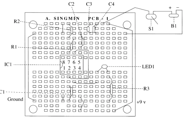
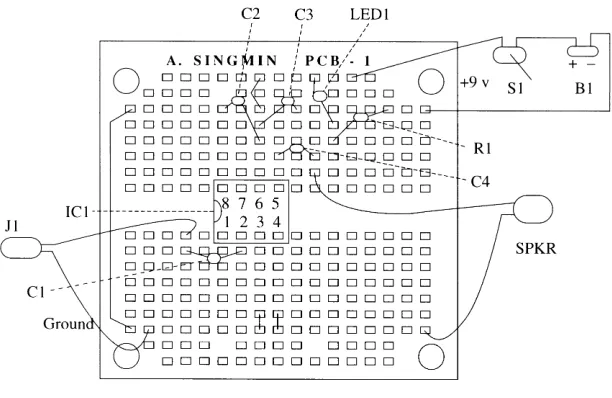
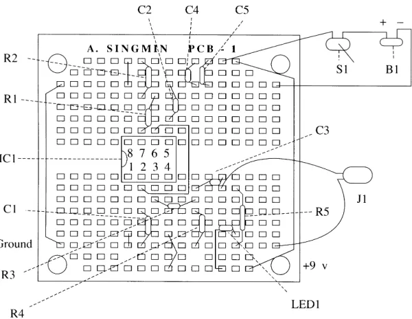
The layout designs for the projects in the next chapter are for a dedicated assembly board—the SINGMIN PCB—which I designed and manufactured in response to a lack of suitable assembly boards available at that time. Since then, however, with continual advances being made in the availability of elec-tronic components for the hobbyist, there are likely more efficient assembly boards available today. My original layouts can be used as a template for laying out your assembly board of choice. Thus, the parts lists for each project refer to a general-purpose assembly board rather than the SINGMIN PCB board. The circuit projects described in this book give full schematic details and a sug-gested component layout scheme for total completeness. Armed with those two diagrams, you should have little difficulty getting the circuits to work the first time.
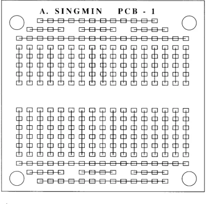
The SINGMIN PCB emerged out of the need to find a better solution to the current methods for prototyping simple projects. The top view of the SINGMIN PCB is shown in Figure 16-1. The way it is shown in the figure, with the legend “SINGMIN PCB-1” at the top of the board, is the way you would correctly orient it for your use. The size of the board is 4 inches by 4.5 inches, although it may be split or quartered into separate, self-contained boards. Sep-arating the SINGMIN PCB into individual sections is done within seconds by merely grasping the board and snapping along the guidelines running horizon-tally and vertically through the center of the board. For a neater finish, you can smooth down the edges of the board after splitting them apart, but this step is not critical.
The underside of the SINGMIN PCB interconnects various rows and columns together. The markings on the top of the board show you the routing of the interconnections. This arrangement is shown in Figure 16-2. Notice that there are two distinct and separate regions on the board. The central area con-sists of columns that are connected from top to bottom. The upper and lower sections consist of rows connected from left to right. This particular arrange-ment has been developed to complearrange-ment the current method of using ICs in
Figure 16-1 Top view of the SINGMIN PCB universal circuit assembly board
hobby projects, thus obviating the need to provide a split supply voltage when using the typical single 9-volt battery.
Integrated circuits also often require connections to the positive and negative supply from either the upper half or lower half of the IC (you’ll see this later in the projects chapter). To accommodate these requirements, the arrangement shown in Figure 16-3 identifies these particular areas for connec-tion. Linking is always done on the top surface (so that the interconnection is always visible), typically so that the positive supply rail is available both at the top and bottom of the board, and similarly so for the negative rail. Because of the generous amount of solder points available, there is plenty of room for the simple projects later described in this book. Hence, there is a lot of flexibility as to where components can be placed. Nothing could be simpler and more satis-fying for the beginner than having an easy-to-use board that eliminates the tedium of trying to fabricate a makeshift assembly medium.
The use of an IC socket is well worth the extra effort because the benefits to be gained are immense. Any errors in locating the IC can be easily rectified merely by unplugging the device and reinserting it the correct way. In the unlikely event of an actual IC failure, replacement could not be simpler.
It is highly recommended that you become familiar with handling and placing the electronic components before attempting any soldering. Compo-nents will not only vary in size but there will also be considerable differences in the way components are bent to shape and actually inserted. Always start with the IC socket because this gives you a starting frame of reference from which the rest of the components can be added. Insert the IC socket and bend The SINGMIN PCB Circuit Assembly Board 41
the leads back to secure. Because of the simplicity of the circuit projects described here and the large board area available for placement of compo-nents, the IC socket need not be rigidly located as per the described layout. By referring to the circuit schematic and the suggested layout, you can see where the electrical connections have to be made. Once you adhere to that require-ment, the mechanical placement can be anywhere that is convenient. To gain initial familiarity with circuit construction, space out the components as much as possible.
After all of the on-board components have been inserted, check thoroughly from both the top and underside for correct alignment with the schematic and layout diagrams. Be thorough at this stage because it is easy to correct a placement error before soldering has been started. After the compo-nents have been soldered, the rectification of a mistake becomes a little more difficult because some dexterity is needed to desolder components. But, in the end, learning to correct mistakes just takes practice, as with any task.
CHAPTER
17
Construction Details for
10 Simple Projects
Project #1: Fixed Low-Frequency LED Flasher
It is highly recommended that Project #1 be built as a learning exercise because all of the detailed assembly and handling instructions you will need for the later projects are only given with this project. Projects #2 through #12 assume that you have already acquired some project construction experience.
Project #1 is one of the simplest circuits to begin with. This circuit, when completed, causes a light-emitting diode (LED) to flash or pulse alternately on and off at a very slow rate, that is, at a low frequency. It could be used as a dummy car alarm indicator. You sometimes see these tiny pulsating lights in expensive cars protected by sophisticated car security systems, warning you that the car alarm is armed and ready. For this design, the LED flashes on for a brief period and stays off for a relatively longer period. Because additional current is consumed from the battery every time the LED comes on, this long rest period conserves battery power. The brightness of the indicator LED is also limited, again in order to preserve battery power.
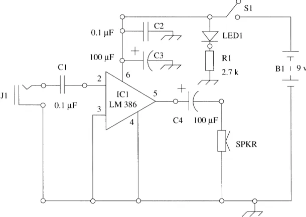
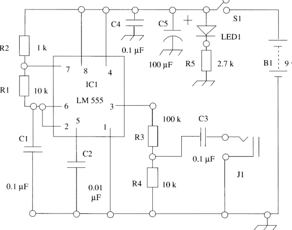
Circuit Description
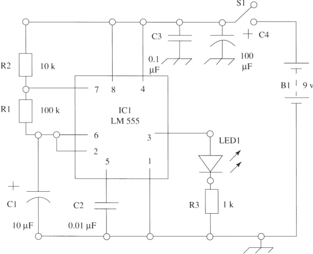
The 555 timer integrated circuit (IC) is configured in an oscillating mode that results in a continuous train of pulses being generated. The frequency-determining components have been chosen to give a very slow pulse rate. Two resistors and a capacitor determine the flashing rate of the LED. Power is supplied from a 9-volt battery.
Parts List