Lampiran 1. Konfigurasi Program Menghitung Data Komputer (Assembly)
/*******************************************************
This program was created by the
CodeWizardAVR V2.60 Standard
Automatic Program Generator
© Copyright 1998-2012 Pavel Haiduc, HP InfoTech s.r.l.
http://www.hpinfotech.com
AVR Core Clock frequency: 16.000000 MHz
Memory model : Small
#define led PORTC.7
#define peltier PORTC.6
// Declare your global variables here
unsigned char fc_l, fc_h;
// Standard Input/Output functions
// Timer1 overflow interrupt service routine
interrupt [TIM1_OVF] void timer1_ovf_isr(void)
{
// Reinitialize Timer1 value
TCNT1H=0x9E58 >> 8;
TCNT1L=0x9E58 & 0xff;
// Place your code here
led = ! led;
}
#define ADC_VREF_TYPE ((1<<REFS1) | (1<<REFS0) | (0<<ADLAR))
// Read the AD conversion result
unsigned int read_adc(unsigned char adc_input)
{
ADMUX=adc_input | ADC_VREF_TYPE;
// Delay needed for the stabilization of the ADC input voltage
delay_us(10);
// Start the AD conversion
ADCSRA|=(1<<ADSC);
// Wait for the AD conversion to complete
while ((ADCSRA & (1<<ADIF))==0);
ADCSRA|=(1<<ADIF);
return ADCW;
}
unsigned int channel_0 (void)
{
float v_ch_0;
unsigned char idx;
v_ch_0 = 0;
for (idx = 0; idx < 150; idx ++)
v_ch_0 = v_ch_0 + read_adc(0);
}
v_ch_0 = v_ch_0/150;
return v_ch_0;
}
void main(void)
{
// Declare your local variables here
unsigned int v_0, v_1;
// Input/Output Ports initialization
// Port A initialization
// Function: Bit7=In Bit6=In Bit5=In Bit4=In Bit3=In Bit2=In Bit1=In Bit0=In
DDRA=(0<<DDA7) | (0<<DDA6) | (0<<DDA5) | (0<<DDA4) | (0<<DDA3) |
(0<<DDA2) | (0<<DDA1) | (0<<DDA0);
// State: Bit7=T Bit6=T Bit5=T Bit4=T Bit3=T Bit2=T Bit1=T Bit0=T
PORTA=(0<<PORTA7) | (0<<PORTA6) | (0<<PORTA5) | (0<<PORTA4) |
(0<<PORTA3) | (0<<PORTA2) | (0<<PORTA1) | (0<<PORTA0);
// Port B initialization
// Function: Bit7=In Bit6=In Bit5=In Bit4=In Bit3=In Bit2=In Bit1=In Bit0=In
DDRB=(0<<DDB7) | (0<<DDB6) | (0<<DDB5) | (0<<DDB4) | (0<<DDB3) |
(0<<DDB2) | (0<<DDB1) | (0<<DDB0);
// State: Bit7=T Bit6=T Bit5=T Bit4=T Bit3=T Bit2=T Bit1=T Bit0=T
PORTB=(0<<PORTB7) | (0<<PORTB6) | (0<<PORTB5) | (0<<PORTB4) |
(0<<PORTB3) | (0<<PORTB2) | (0<<PORTB1) | (0<<PORTB0);
// Port C initialization
// Function: Bit7=Out Bit6=In Bit5=In Bit4=In Bit3=In Bit2=In Bit1=In Bit0=In
DDRC=(1<<DDC7) | (0<<DDC6) | (0<<DDC5) | (0<<DDC4) | (0<<DDC3) |
(0<<DDC2) | (0<<DDC1) | (0<<DDC0);
PORTC=(0<<PORTC7) | (0<<PORTC6) | (0<<PORTC5) | (0<<PORTC4) |
(0<<PORTC3) | (0<<PORTC2) | (0<<PORTC1) | (0<<PORTC0);
// Port D initialization
// Function: Bit7=In Bit6=In Bit5=In Bit4=In Bit3=In Bit2=In Bit1=In Bit0=In
DDRD=(0<<DDD7) | (0<<DDD6) | (0<<DDD5) | (0<<DDD4) | (0<<DDD3) |
(0<<DDD2) | (0<<DDD1) | (0<<DDD0);
// State: Bit7=T Bit6=T Bit5=T Bit4=T Bit3=T Bit2=T Bit1=T Bit0=T
PORTD=(0<<PORTD7) | (0<<PORTD6) | (0<<PORTD5) | (0<<PORTD4) |
(0<<PORTD3) | (0<<PORTD2) | (0<<PORTD1) | (0<<PORTD0);
// Timer/Counter 0 initialization
// Clock source: System Clock
// Clock value: Timer 0 Stopped
// Mode: Normal top=0xFF
// OC0 output: Disconnected
TCCR0=(0<<WGM00) | (0<<COM01) | (0<<COM00) | (0<<WGM01) | (0<<CS02) |
(0<<CS01) | (0<<CS00);
TCNT0=0x00;
OCR0=0x00;
// Timer/Counter 1 initialization
// Clock source: System Clock
// Clock value: 250.000 kHz
// Mode: Normal top=0xFFFF
// OC1A output: Disconnected
// OC1B output: Disconnected
// Noise Canceler: Off
// Input Capture on Falling Edge
// Timer Period: 0.1 s
// Timer1 Overflow Interrupt: On
// Input Capture Interrupt: Off
// Compare B Match Interrupt: Off
TCCR1A=(0<<COM1A1) | (0<<COM1A0) | (0<<COM1B1) | (0<<COM1B0) |
(0<<WGM11) | (0<<WGM10);
TCCR1B=(0<<ICNC1) | (0<<ICES1) | (0<<WGM13) | (0<<WGM12) | (0<<CS12) |
(1<<CS11) | (1<<CS10);
TCNT1H=0x9E;
// Timer/Counter 2 initialization
// Clock source: System Clock
// Clock value: Timer2 Stopped
// Mode: Normal top=0xFF
// OC2 output: Disconnected
ASSR=0<<AS2;
TCCR2=(0<<WGM20) | (0<<COM21) | (0<<COM20) | (0<<WGM21) | (0<<CS22) |
(0<<CS21) | (0<<CS20);
TCNT2=0x00;
OCR2=0x00;
// Timer(s)/Counter(s) Interrupt(s) initialization
TIMSK=(0<<OCIE2) | (0<<TOIE2) | (0<<TICIE1) | (0<<OCIE1A) | (0<<OCIE1B) |
(1<<TOIE1) | (0<<OCIE0) | (0<<TOIE0);
// External Interrupt(s) initialization
// INT0: Off
// INT1: Off
MCUCR=(0<<ISC11) | (0<<ISC10) | (0<<ISC01) | (0<<ISC00);
MCUCSR=(0<<ISC2);
// USART initialization
// Communication Parameters: 8 Data, 1 Stop, No Parity
// USART Receiver: On
// USART Transmitter: On
// USART Mode: Asynchronous
// USART Baud Rate: 9600
UCSRA=(0<<RXC) | (0<<TXC) | (0<<UDRE) | (0<<FE) | (0<<DOR) | (0<<UPE) |
(0<<U2X) | (0<<MPCM);
UCSRB=(0<<RXCIE) | (0<<TXCIE) | (0<<UDRIE) | (1<<RXEN) | (1<<TXEN) |
(0<<UCSZ2) | (0<<RXB8) | (0<<TXB8);
UCSRC=(1<<URSEL) | (0<<UMSEL) | (0<<UPM1) | (0<<UPM0) | (0<<USBS) |
(1<<UCSZ1) | (1<<UCSZ0) | (0<<UCPOL);
UBRRH=0x00;
UBRRL=0x67;
// Analog Comparator initialization
// Analog Comparator: Off
ACSR=(1<<ACD) | (0<<ACBG) | (0<<ACO) | (0<<ACI) | (0<<ACIE) | (0<<ACIC) |
(0<<ACIS1) | (0<<ACIS0);
// ADC initialization
// ADC Clock frequency: 125.000 kHz
// ADC Voltage Reference: Int., cap. on AREF
// ADC High Speed Mode: Off
// ADC Auto Trigger Source: ADC Stopped
ADMUX=ADC_VREF_TYPE;
ADCSRA=(1<<ADEN) | (0<<ADSC) | (0<<ADATE) | (0<<ADIF) | (0<<ADIE) |
(1<<ADPS2) | (1<<ADPS1) | (1<<ADPS0);
// SPI initialization
// SPI disabled
SPCR=(0<<SPIE) | (0<<SPE) | (0<<DORD) | (0<<MSTR) | (0<<CPOL) |
(0<<CPHA) | (0<<SPR1) | (0<<SPR0);
// TWI initialization
// TWI disabled
TWCR=(0<<TWEA) | (0<<TWSTA) | (0<<TWSTO) | (0<<TWEN) | (0<<TWIE);
// Global enable interrupts
#asm("sei")
while (1)
{
// Place your code here
v_0 = channel_0();
v_0 = (v_0 * 9)/7;
addr_0 = '0';
// v_0 = 256;
hi_0 = v_0 >> 8;
lo_0 = v_0 & 0x00ff;
putchar(addr_0);
putchar(lo_0);
putchar(hi_0);
delay_ms(25);
}
Lampiran 2. Konfigurasi Program Menghitung Data Komputer (Visual Basic)
Private Sub Command1_Click()
MSComm1.PortOpen = False
Close intHandle
End
End Sub
Private Sub Command3_Click()
Print #intHandle, "There will be a new line after this!"
Print #intHandle, "Last line in file!"; '<- Notice semicolon.
End Sub
Private Sub Form_Load()
If MSComm1.PortOpen = False Then
MSComm1.PortOpen = True
MSComm1.RThreshold = 3
MSComm1.NullDiscard = False
MSComm1.InputMode = comInputModeText
End If
End Sub
Private Sub MSComm1_OnComm()
End If
End Sub
Private Sub Timer1_Timer()
Dim intHandle As Integer
intHandle = FreeFile
Text3.Text = Time$() ' catat untuk waktu
Open "C:\Users\wahyuni\refri.txt" For Append As intHandle
Print #intHandle, Text1.Text, Text3.Text, Chr(13), Chr(10)
Close intHandle
Lampiran 3. Konfigurasi Operasi Mikrokontroller
/*******************************************************
This program was created by the
CodeWizardAVR V2.60 Standard
Automatic Program Generator
© Copyright 1998-2012 Pavel Haiduc, HP InfoTech s.r.l.
http://www.hpinfotech.com
Chip type : ATmega32
Program type : Application
AVR Core Clock frequency: 16.000000 MHz
Memory model : Small
External RAM size : 0
Data Stack size : 128
*******************************************************/
#include <mega32.h>
#include <delay.h>
#define led PORTC.7
#define peltier PORTC.6
// Declare your global variables here
// Standard Input/Output functions
#include <stdio.h>
// Timer1 overflow interrupt service routine
interrupt [TIM1_OVF] void timer1_ovf_isr(void)
{
// Reinitialize Timer1 value
TCNT1H=0x9E58 >> 8;
TCNT1L=0x9E58 & 0xff;
// Place your code here
led = ! led;
}
#define ADC_VREF_TYPE ((1<<REFS1) | (1<<REFS0) |
(0<<ADLAR))
// Read the AD conversion result
unsigned int read_adc(unsigned char adc_input)
{
ADMUX=adc_input | ADC_VREF_TYPE;
// Delay needed for the stabilization of the ADC input voltage
delay_us(10);
// Start the AD conversion
ADCSRA|=(1<<ADSC);
// Wait for the AD conversion to complete
while ((ADCSRA & (1<<ADIF))==0);
return ADCW;
}
unsigned int channel_0 (void)
{
float v_ch_0;
unsigned char idx;
v_ch_0 = 0;
for (idx = 0; idx < 150; idx ++)
{
v_ch_0 = v_ch_0 + read_adc(0);
}
v_ch_0 = v_ch_0/150;
return v_ch_0;
}
void main(void)
{
// Declare your local variables here
unsigned int v_0, v_1;
// Input/Output Ports initialization
// Port A initialization
DDRA=(0<<DDA7) | (0<<DDA6) | (0<<DDA5) | (0<<DDA4) |
(0<<DDA3) | (0<<DDA2) | (0<<DDA1) | (0<<DDA0);
// State: Bit7=T Bit6=T Bit5=T Bit4=T Bit3=T Bit2=T Bit1=T Bit0=T
PORTA=(0<<PORTA7) | (0<<PORTA6) | (0<<PORTA5) |
(0<<PORTA4) | (0<<PORTA3) | (0<<PORTA2) | (0<<PORTA1) |
(0<<PORTA0);
// Port B initialization
// Function: Bit7=In Bit6=In Bit5=In Bit4=In Bit3=In Bit2=In Bit1=In
Bit0=In
DDRB=(0<<DDB7) | (0<<DDB6) | (0<<DDB5) | (0<<DDB4) |
(0<<DDB3) | (0<<DDB2) | (0<<DDB1) | (0<<DDB0);
// State: Bit7=T Bit6=T Bit5=T Bit4=T Bit3=T Bit2=T Bit1=T Bit0=T
PORTB=(0<<PORTB7) | (0<<PORTB6) | (0<<PORTB5) |
(0<<PORTB4) | (0<<PORTB3) | (0<<PORTB2) | (0<<PORTB1) |
(0<<PORTB0);
// Port C initialization
// Function: Bit7=Out Bit6=In Bit5=In Bit4=In Bit3=In Bit2=In Bit1=In
Bit0=In
DDRC=(1<<DDC7) | (0<<DDC6) | (0<<DDC5) | (0<<DDC4) |
(0<<DDC3) | (0<<DDC2) | (0<<DDC1) | (0<<DDC0);
// State: Bit7=0 Bit6=T Bit5=T Bit4=T Bit3=T Bit2=T Bit1=T Bit0=T
PORTC=(0<<PORTC7) | (0<<PORTC6) | (0<<PORTC5) |
(0<<PORTC4) | (0<<PORTC3) | (0<<PORTC2) | (0<<PORTC1) |
(0<<PORTC0);
// Port D initialization
DDRD=(0<<DDD7) | (0<<DDD6) | (0<<DDD5) | (0<<DDD4) |
(0<<DDD3) | (0<<DDD2) | (0<<DDD1) | (0<<DDD0);
// State: Bit7=T Bit6=T Bit5=T Bit4=T Bit3=T Bit2=T Bit1=T Bit0=T
PORTD=(0<<PORTD7) | (0<<PORTD6) | (0<<PORTD5) |
(0<<PORTD4) | (0<<PORTD3) | (0<<PORTD2) | (0<<PORTD1) |
(0<<PORTD0);
// Timer/Counter 0 initialization
// Clock source: System Clock
// Clock value: Timer 0 Stopped
// Mode: Normal top=0xFF
// OC0 output: Disconnected
TCCR0=(0<<WGM00) | (0<<COM01) | (0<<COM00) | (0<<WGM01) |
(0<<CS02) | (0<<CS01) | (0<<CS00);
TCNT0=0x00;
OCR0=0x00;
// Timer/Counter 1 initialization
// Clock source: System Clock
// Clock value: 250.000 kHz
// Mode: Normal top=0xFFFF
// OC1A output: Disconnected
// OC1B output: Disconnected
// Noise Canceler: Off
// Input Capture on Falling Edge
// Timer Period: 0.1 s
// Timer1 Overflow Interrupt: On
// Compare A Match Interrupt: Off
// Compare B Match Interrupt: Off
TCCR1A=(0<<COM1A1) | (0<<COM1A0) | (0<<COM1B1) |
(0<<COM1B0) | (0<<WGM11) | (0<<WGM10);
TCCR1B=(0<<ICNC1) | (0<<ICES1) | (0<<WGM13) | (0<<WGM12) |
(0<<CS12) | (1<<CS11) | (1<<CS10);
TCNT1H=0x9E;
TCNT1L=0x58;
ICR1H=0x00;
ICR1L=0x00;
OCR1AH=0x00;
OCR1AL=0x00;
OCR1BH=0x00;
OCR1BL=0x00;
// Timer/Counter 2 initialization
// Clock source: System Clock
// Clock value: Timer2 Stopped
// Mode: Normal top=0xFF
// OC2 output: Disconnected
ASSR=0<<AS2;
TCCR2=(0<<WGM20) | (0<<COM21) | (0<<COM20) | (0<<WGM21) |
(0<<CS22) | (0<<CS21) | (0<<CS20);
TCNT2=0x00;
OCR2=0x00;
TIMSK=(0<<OCIE2) | (0<<TOIE2) | (0<<TICIE1) | (0<<OCIE1A) |
(0<<OCIE1B) | (1<<TOIE1) | (0<<OCIE0) | (0<<TOIE0);
// External Interrupt(s) initialization
// INT0: Off
// INT1: Off
// INT2: Off
MCUCR=(0<<ISC11) | (0<<ISC10) | (0<<ISC01) | (0<<ISC00);
MCUCSR=(0<<ISC2);
// USART initialization
// Communication Parameters: 8 Data, 1 Stop, No Parity
// USART Receiver: On
// USART Transmitter: On
// USART Mode: Asynchronous
// USART Baud Rate: 9600
UCSRA=(0<<RXC) | (0<<TXC) | (0<<UDRE) | (0<<FE) | (0<<DOR) |
(0<<UPE) | (0<<U2X) | (0<<MPCM);
UCSRB=(0<<RXCIE) | (0<<TXCIE) | (0<<UDRIE) | (1<<RXEN) |
(1<<TXEN) | (0<<UCSZ2) | (0<<RXB8) | (0<<TXB8);
UCSRC=(1<<URSEL) | (0<<UMSEL) | (0<<UPM1) | (0<<UPM0) |
(0<<USBS) | (1<<UCSZ1) | (1<<UCSZ0) | (0<<UCPOL);
UBRRH=0x00;
UBRRL=0x67;
// Analog Comparator initialization
ACSR=(1<<ACD) | (0<<ACBG) | (0<<ACO) | (0<<ACI) | (0<<ACIE) |
(0<<ACIC) | (0<<ACIS1) | (0<<ACIS0);
// ADC initialization
// ADC Clock frequency: 125.000 kHz
// ADC Voltage Reference: Int., cap. on AREF
// ADC High Speed Mode: Off
// ADC Auto Trigger Source: ADC Stopped
ADMUX=ADC_VREF_TYPE;
ADCSRA=(1<<ADEN) | (0<<ADSC) | (0<<ADATE) | (0<<ADIF) |
(0<<ADIE) | (1<<ADPS2) | (1<<ADPS1) | (1<<ADPS0);
SFIOR=(1<<ADHSM) | (0<<ADTS2) | (0<<ADTS1) | (0<<ADTS0);
// SPI initialization
// SPI disabled
SPCR=(0<<SPIE) | (0<<SPE) | (0<<DORD) | (0<<MSTR) | (0<<CPOL) |
(0<<CPHA) | (0<<SPR1) | (0<<SPR0);
// TWI initialization
// TWI disabled
TWCR=(0<<TWEA) | (0<<TWSTA) | (0<<TWSTO) | (0<<TWEN) |
(0<<TWIE);
// Global enable interrupts
#asm("sei")
while (1)
// Place your code here
v_0 = channel_0();
v_0 = (v_0 * 9)/7;
addr_0 = '0';
// v_0 = 256;
hi_0 = v_0 >> 8;
lo_0 = v_0 & 0x00ff;
putchar(addr_0);
putchar(lo_0);
putchar(hi_0);
delay_ms(25);
}
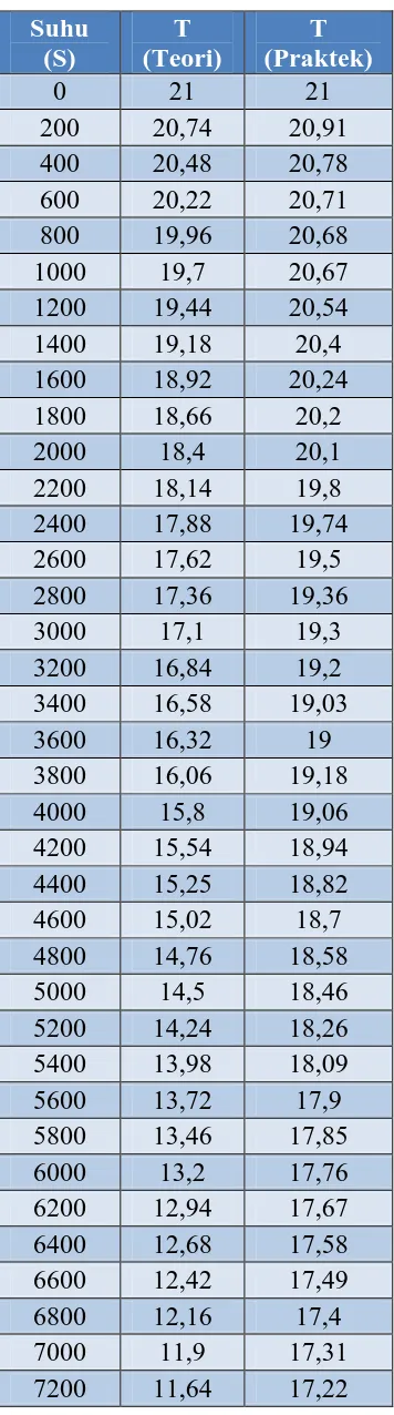
Lampiran 4. Data Pengukuran Suhu
1. Tabel pengukuran dengan beban 1 liter air
Waktu (s) Suhu(teori) Suhu(Praktek)
15800 0,46 9,32
16000 0,2 8,98
16200 -0,06 8,84 16400 -0,32 8,58 16600 -0,58 8,43 16800 -0,84 8,18
17000 -1,1 7,94
17200 -1,36 7,7
17400 -1,62 7,42 17600 -1,88 7,06 17800 -2,14 6,82
18000 -2,4 6,56
18200 -2,66 6,12 18400 -2,92 5,94 18600 -3,18 5,68
18800 -3,44 5,4
19000 -3,7 5,22
19200 -3,96 5
19400 -4,22 4,82
31600 -6,65 6,2
32000 -7 5,98
32400 -7,35 5,7
32800 -7,7 5,45
33200 -8,05 5,3
33600 -8,4 5,06
34000 -8,75 4,84
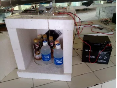
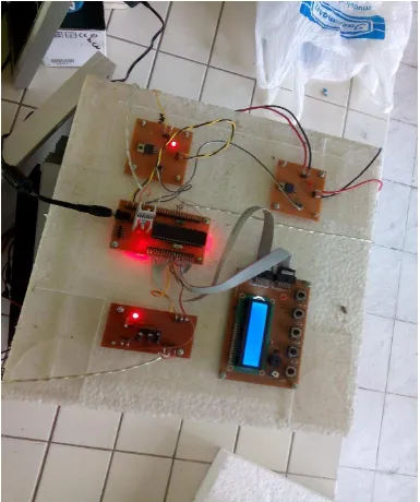
Lampiran 5. Gambar Kulkas Mini