Domain
Engineering
Iris Reinhartz-Berger · Arnon Sturm
Tony Clark · Sholom Cohen
Jorn Bettin
Editors
Product Lines,
Languages, and
Conceptual Models
Domain Engineering
Iris Reinhartz-Berger
Arnon Sturm
Tony Clark
Sholom Cohen
Jorn Bettin
Editors
Domain Engineering
Product Lines, Languages,
and Conceptual Models
123
Editors
Springer Heidelberg New York Dordrecht London
Library of Congress Control Number: 2013942395 ACM Computing Classification: D.2, I.6 © Springer-Verlag Berlin Heidelberg 2013
This work is subject to copyright. All rights are reserved by the Publisher, whether the whole or part of the material is concerned, specifically the rights of translation, reprinting, reuse of illustrations, recitation, broadcasting, reproduction on microfilms or in any other physical way, and transmission or information storage and retrieval, electronic adaptation, computer software, or by similar or dissimilar methodology now known or hereafter developed. Exempted from this legal reservation are brief excerpts in connection with reviews or scholarly analysis or material supplied specifically for the purpose of being entered and executed on a computer system, for exclusive use by the purchaser of the work. Duplication of this publication or parts thereof is permitted only under the provisions of the Copyright Law of the Publisher’s location, in its current version, and permission for use must always be obtained from Springer. Permissions for use may be obtained through RightsLink at the Copyright Clearance Center. Violations are liable to prosecution under the respective Copyright Law.
The use of general descriptive names, registered names, trademarks, service marks, etc. in this publication does not imply, even in the absence of a specific statement, that such names are exempt from the relevant protective laws and regulations and therefore free for general use.
While the advice and information in this book are believed to be true and accurate at the date of publication, neither the authors nor the editors nor the publisher can accept any legal responsibility for any errors or omissions that may be made. The publisher makes no warranty, express or implied, with respect to the material contained herein.
Printed on acid-free paper
Springer is part of Springer Science+Business Media (www.springer.com)
Preface: Introduction to Domain Engineering:
Product Lines, Languages, and Conceptual
Models
A domainis an area of knowledge that uses common concepts for describing phe-nomena, requirements, problems, capabilities, and solutions. A domain is usually associated with well-defined or partially defined terminology. This terminology refers to the basic concepts in that domain, their definitions (i.e., their semantic meanings), and their relationships. It may also refer to behaviors that are desired, forbidden, or perceived within the domain.Domain engineeringis a set of activities that aim to develop, maintain, and manage the creation and evolution of domains.
Domain engineering has become of special interest to the information systems and software engineering communities for several reasons. These reasons include, in particular, the need to maintain and use existing knowledge, the need to manage increasing requirements for variability of information and software systems, and the need to obtain, formalize, and share expertise in different, evolving domains.
Domain engineering as a discipline has practical significance as it can provide methods and techniques that may help reduce time-to-market, development cost, and projects risks, on the one hand, and help improve product quality and performance on a consistent basis, on the other hand. It is used, researched, and studied in various fields, predominantly: software product line engineering (SPLE), domain-specific language engineering (DSLE), and conceptual modeling.
This book presents a collection of state-of-the-art research studies in the domain engineering field. About half of the chapters in this collection originated from a series of workshops, named domain engineering, which were associated with the Conference of Advanced Information Systems Engineering (CAiSE) during the years 2009–2011 and with the international confer-ence on conceptual modeling (also known as the ER conferconfer-ence) in 2010. The authors of the other chapters were personally invited to contribute to this book. The chapters are organized in three parts. The first part includes research studies that deal with domain engineering in SPLE. The second part refers to domain engineering as a research topic within the field of DSLE. Finally, the third part presents research studies that deal with domain engineering within the field of conceptual modeling.
v
vi Preface: Introduction to Domain Engineering: Product Lines, Languages,...
Part I: Software Product Line Engineering
A software product line is a set of software-intensive systems that share a common, managed set of features satisfying the specific needs of a particular market segment or mission and that are developed from a common set of core assets in a prescribed way [1, 8]. While reuse has always made sense as a means to take advantage of the commonality across systems, most reuse strategies fail to have any real technical or economic impact. SPLE is a discipline that addresses technical and economic benefit and achieves strategic reuse of software across the product line through: (1) capturing common features and factoring the variations across the domain or domains of a product line; (2) developing core assets used in constructing the systems of the product line; (3) promulgating and enforcing a prescribed way for building software product line assets and systems; and (4) evolving both core assets and products in the product line to sustain their applicability.
Although SPLE has been a recognized discipline within the software engi-neering community for two decades, the practice of SPLE in industry still faces significant challenges in achieving strategic reuse. Challenges are seen in each of the four areas mentioned above. Specific examples include: (1) capturing commonality—modeling and representation approaches, tools, and analysis for variation and variation management; (2) developing assets—architecture design approaches including real-time embedded, design patterns, automatic generation of software, and design approaches including aspect-orientation; and (3) building software—implementation of software assets for reuse, composition techniques, and use of domain-specific languages (DSLs) for software construction. In addition, there is a need to deal with the evolution of the core assets and the product line systems and a need for specific tools to assist the coevolution of product line core assets and dependent systems.
In the field of SPLE, domain engineering deals with specifying, designing, implementing, and managing reusable assets, such as specification sets, patterns, and components, that may be suitable, after customization, adaptation, or even extension, to families of software products. The focus of domain engineering in this field is on conducting commonality and variability analysis and representing the results of this analysis in a comprehensible way. Commonly, feature-oriented methods and UML profiles are used for this purpose.
The chapters in this part of the book deal with application of domain engineering to address some of the aforementioned challenges. Two chapters deal with domain engineering to capture commonality and manage variation across a software product line:
• “Separating concerns in feature models: Retrospective and support for multi-views” by Mathieu Acher, Arnaud Hubaux, Patrick Heymans, Thein Than Tun, Philippe Lahire, and Philippe Collet looks at managing common features and their variants in software product lines with thousands of features. This chapter describes the separation of concerns, that can be applied to partition the feature space.
Preface: Introduction to Domain Engineering: Product Lines, Languages,... vii
• “A survey of feature location techniques” by Julia Rubin and Marsha Chechik examines over 20 techniques that offer automated or semi-automated approaches to isolate features from existing software. This chapter provides a description of the overarching technology for isolating features for software code and analyzes the potential that each of the 20Ctechniques offers. The chapter also provides guidance in selecting the appropriate technique.
One chapter deals with architecture and design for software product lines, specifically those software product lines that are real-time (RT) embedded:
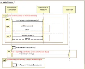
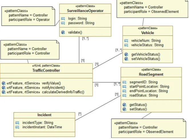
• “Modeling real-time design patterns with the UML-RTDP profile” by Saoussen Rekhis, Nadia Bouassida, Rafik Bouaziz, Claude Duvallet, and Bruno Sadeg applies domain engineering to design RT patterns for capturing commonality and managing variation across the software product line. This chapter introduces UML-based models that represent the static and dynamic patterns of a software product line architecture for RT systems. It describes the application of these models in an example of an RT control system.
The two remaining chapters in this part apply domain engineering to develop techniques for building core assets and systems in the software product line:
• “When aspect-orientation meets software product line engineering” by Iris Reinhartz-Berger discusses an approach that melds aspect-oriented and SPLE methods through domain engineering. The approach uses the Application-based DOmain Modeling (ADOM) method to support families of aspects and weave them to families of software products. Reuse is enhanced through the three levels addressed by ADOM: language, domain, and application.
• “Utilizing application frameworks: a domain engineering approach” by Arnon Sturm and Oded Kramer also uses ADOM. In this chapter, the modeling approach supports specification and use of frameworks as a construct to support reuse across the software product line. ADOM also contributes to domain-specific languages to reduce the development effort and increase their reusability and code quality.
Part II: Domain-Specific Language Engineering
DSLs are specification or programming languages tailored to specific domains [6, 7]. These languages are developed in a domain engineering process and are later used to develop and maintain solutions (i.e., software systems) in the specific domains. The focus on a specific domain is achieved by abstracting from general programming language implementation details such as variable locations and control structures. The resulting DSL features correspond to domain elements and are often referred to as declarative (as opposed to imperative) because they focus on expressing desirable states of the problem domain rather than computations in the solution domain. The benefits of adopting DSLs include increased productivity,
viii Preface: Introduction to Domain Engineering: Product Lines, Languages,...
improved quality, reuse of experts’ knowledge, and, perhaps most importantly, better maintainability [6, 7].
Conceptually, a DSL is a formal language that is expected to be understood by domain experts and that can be interpreted by domain-specific software tools to produce lower level specifications. Practically, a DSL is a preferably small language that focuses on a particular aspect of software systems (e.g., [3]) and that is used by domain-specific software tools to generate code in a general purpose programming language or other lower level formal specification languages, e.g., [7]. Examples of domain-specific programming approaches are elaborated in [4, 5].
Domain-specific language engineering (DSLE) is concerned with methods and tools for specifying and utilizing such languages. This includes the identification of relevant language concepts and their relationships, the determination of the most appropriate level of abstraction for the envisaged users of the language, and the specification of all required transformations.
Although the practice of DSLE has evolved considerably in the last two decades, a number of challenges remain. There is a need to study the ways in which people use DSLs and to what extent. In line with the increasing popularity of DSLs, there is a need to evaluate the ways in which DSLs are composed, to examine maintainability and interoperability, and to devise mechanisms that enable end users to extend DSLs. The trade-offs between using general purpose languages and DSLs also merit further discussion. From an engineering perspective, there is a need to explore how DSL elements can be reused, which types of transformation are required, what best practices can be distilled from detailed case studies, how to define and evolve the semantics of a DSL, and how to evaluate the design and implementation of a DSL.
In this part of the book, we have gathered five chapters that address some of the challenges mentioned above.
The first chapter discusses the notion of domain-specific languages:
• “Domain-specific modeling languages—requirement analysis and design guide-lines” by Ulrich Frank attempts to provide instructions for developing a domain-specific modeling language. In particular, this chapter introduces a set of guidelines, which consist of requirements for the meta-modeling language, as well as a detailed process description of the stages to devise a new DSL.
The following two chapters discuss the design process of domain-specific languages. Designing a DSL involves the creation of a new formal language, and therefore it is important to investigate the emergence of new languages as well as their engineering:
• “DSLs and standardization: Friends or foes?” by Øystein Haugen argues that creating a good language requires knowledge not only of the domain but also of the language design process. This chapter discusses the tension between DSLs and standardization efforts, demonstrates how DSLs can benefit from standardization, and provides a comprehensive example of language evolution and standardization.
Preface: Introduction to Domain Engineering: Product Lines, Languages,... ix
• “Domain engineering for software tools” by Tony Clark and Balbir Barn proposes a language-driven approach that elaborates the notion of domain-specific tool chains and related tool interoperability challenges. The approach presented in the chapter views domains as languages and emphasizes the need for modularity, in particular the need for modular composition of domains and tool chains. The suggested approach for tool design involves a model of the semantic domain, a model of the abstract syntax, a model of the concrete syntax, as well as a model of the relationships between the semantic domain and the abstract syntax.
A key motivation for developing one or more DSLs for the same domain is the desire to capture all the meta-data that is needed to automate the production of detailed artifacts (such as code) from the abstract concepts supported by the DSLs. A common way of producing derived artifacts is through model transformation. Although a large number of model transformation languages have been developed, there are only few heuristics for engineering model transformation languages. The fourth chapter in this part tackles this issue:
• “Modeling a model transformation language” by Eugene Syriani, Jeff Gray, and Hans Vangheluwe introduces a technique for developing model transformation languages that refers to each language as a DSL and that includes a model of all domain concepts at the appropriate level of abstraction.
As developing a DSL is a complex task that involves stakeholders from different disciplines, a cooperative environment that supports cross-disciplinary collaboration is required. The fifth and last chapter in this part addresses this challenge:
• “A Reconciliation framework to support cooperative work with DSM” by Amanuel Alemayehu Koshima, Vincent Englebert, and Philippe Thiran proposes a communication framework that links the changes made by the language engineers and their effects on DSL users. This framework is concerned with the effects of language evolution and the propagation of changes in tool chains and across the stakeholders and the language user community.
Part III: Conceptual Modeling
Before any system can be collaboratively developed, used, and maintained, it is necessary to study and understand the domain of discourse. This is commonly done by developing a conceptual model. The main purposes of conceptual models are: (1) supporting communications between different types of stakeholders and especially between developers and users; (2) helping analysts understand the domain of interest, its terminology, and rules; (3) providing input for the next development phases, namely top level and detailed design; and (4) documenting the requirements that originate from the real world for maintenance purposes and future reference.
x Preface: Introduction to Domain Engineering: Product Lines, Languages,...
The process of building conceptual models, conceptual modeling, involves devel-oping and maintaining representations of selected phenomena in the application domain [12]. These representations, the conceptual models, are usually developed during the requirements analysis phase of software or information systems devel-opment. Such models aim to capture the essential features of systems in terms of the different categories of entity, their properties, relationships, and their meaning. They are used for representing both structural and dynamic phenomena, usually in a graphic way. Once a conceptual model is constructed and agreed on, it forms a foundational basis for subsequent engineering activities.
Although research in conceptual modeling has existed for many years, its boundaries are quite vague. In particular, conceptual modeling has significant overlap with the field of knowledge engineering [9]. Many of the features of modern notations for conceptual modeling can be traced to examples in both early system design notations and knowledge representation notations, such as conceptual structures [10]. Conceptual modeling also has a strong relationship to ontologies [11], and the question whether conceptual models and ontologies are alternatives of each other is open. Clearly, Conceptual modeling is also related to model-driven architecture (MDA), which has become a significant research topic in recent years. MDA promotes the idea that systems should be modeled at a high level of abstraction and then systems are partially or completely generated from the models. In light of technology improvements, many challenges that concern domain engineering in the context of conceptual modeling arise. In particular, how can the real world be modeled to better support the development, implementation, use, and maintenance of systems? [1] Conceptual modeling applies to many different application domains which raises the question of how to support the representational needs of each domain. Should there be a single universal language for conceptual modeling or several different languages? Do methods that apply to one type of application (finance for example) also apply in another (for example an embedded system)? The representational issue is often addressed using meta-techniques that allow the conceptual modeler to use a standard notation to design a bespoke notation that is used to express the conceptual model. While the best meta-technology is an open question, UML provides profiles that allow the UML standard to be tailored in a number of ways to support new concepts in terms of abstract modeling elements and the ways they are represented on diagrams. Also, following the evolvement of the MDA approach, it is interesting to examine how conceptual models fit into various MDA technologies and processes. Finally, the management of conceptual models is also a challenge, especially those that involve meta-technologies [2]. In addition to the usual problems related to distributed multi-person development, a conceptual model written using a notation that has been specifically defined for this purpose requires care when the meta-model is evolved, otherwise the conceptual model becomes meaningless.
The chapters in this part of the book address some of the challenges mentioned above. The first chapter in this part suggests using domain engineering for formal-izing the knowledge of domain experts.
Preface: Introduction to Domain Engineering: Product Lines, Languages,... xi
• “Model oriented domain analysis and engineering” by Jorn Bettin presents a model-oriented domain analysis and engineering methodology. This methodol-ogy, whose roots are in both SPLE and conceptual modeling, can be used to uncover and formalize the knowledge that is inherent in any software-intensive business or any scientific discipline.
The second chapter analyzes the relationships between different abstraction levels of modeling in order to support the definition of domain-specific modeling languages.
• “Multi-level meta-modeling to underpin the abstract and concrete syntax for domain-specific modelling languages” by Brian Henderson-Sellers and Cesar Gonzalez-Perez discusses the relationships between models, meta-models, mod-eling languages, and ontologies. They further provide a theoretical foundation for the construction of domain-specific modeling languages, exemplifying this foundation on two languages: ISO/IEC 24744 that can be used to define software-intensive development methods and FAML that can be used for the specification of agent-oriented software systems.
The third chapter discusses an ontology-based framework for evaluating and designing conceptual modeling languages.
• “Ontology-based evaluation and design of visual conceptual modeling lan-guages” by Giancarlo Guizzardi addresses another methodological issue and focuses on the evaluation of the suitability of a language to model a set of real-world phenomena in a given domain. In the proposed approach, the suitability can be systematically evaluated by comparing the level of homomorphism between a concrete representation of the worldview underlying the language and an explicit and formal representation of a conceptualization of that domain (represented as a reference ontology).
The fourth chapter addresses the challenge of managing conceptual models in distributed multi-person development.
• “Automating the interoperability of conceptual models in specific development domains” by Oscar Pastor, Giovanni Giachetti, Beatriz Mar´ın, and Francisco Valverde discusses the model management, interoperability, and reuse. In par-ticular, it discusses the problems related to conceptual interoperability across applications in a domain. This chapter introduces a framework for describing levels of conceptual interoperability and the challenges that must be overcome to achieve the various levels and then outlines a process for achieving and automating interoperability through the integration of modeling languages.
As mentioned before, MDA promotes the idea that systems should be modeled at a high level of abstraction and then systems are partially or completely generated from the models. The benefits that are claimed for this approach are that it shields the developer from constantly changing technology platforms, increases quality, and
xii Preface: Introduction to Domain Engineering: Product Lines, Languages,...
makes change easier to manage. The last chapter exemplifies this notion for the domain of geographic databases.
• “Domain and model-driven geographic database design” by Jugurta Lisboa-Filho, Filipe Ribeiro Nalon, Douglas Alves Peixoto, Gustavo Breder Sampaio, and Karla Albuquerque de Vasconcelos Borges describes the use of the MDA approach in the design of databases in the geographical domain. In particular, a UML Profile, called GeoProfile, is proposed and is aligned with international standards of the ISO 191xx series. This chapter also shows that with the automatic transformation of models it is possible to achieve the generation of scripts for spatial databases from a conceptual data schema in a high level of abstraction.
Concluding and Further Remarks
As elaborated above, domain engineering is closely related to several fields, primarily SPLE, DSLE, and conceptual modeling. This book provides a collection of research studies that are related to these three fields. The fields promote domain engineering differently; however, they do have significant overlap. In particular, some of the studies could pertain to more than one field. Therefore, we confirmed our classification with the authors in these cases. Moreover, as the studies are very diverse, they address a variety of important topics related to domain engineering, stressing the importance of this field, providing solutions, and further clarifying existing related challenges.
We believe that the chapters in this book are of interest to researchers, practition-ers, and students of domain engineering in general and of the fields of SPLE, DSLE, and conceptual modeling in particular. Furthermore, given the exponential growth of data on the Web and the growth of the “Internet of Things,” Domain Engineering research may be relevant to other disciplines as well. For example, the emergence of deep chains of Web services highlights that the service concept is relative. A set of Web services developed and operated by one organization can be utilized as part of a platform by another organization. This calls for appropriate conceptual models as well as for DSLs that together facilitate the design of service-oriented architectures. Furthermore, as services may be used in different contexts and hence require different configurations, inspiration to their design as families of services can be taken from the field of SPLE.
Another new opportunity for research is related to the Big Data domain. Big Data is characterized by the “three Vs”:volume,variety, andvelocity (rate of change). The ability to process such data depends on understanding and manipulating the information. Conceptual models can be of great help since they capture the semantics of the information which is important for making matches in the presence of incomplete and noisy input. Furthermore, meta-processing, such as dependency analysis, model transformations, model merge, and slicing, can be used to address
Preface: Introduction to Domain Engineering: Product Lines, Languages,... xiii
multiple data sources. DSLs can be used to develop languages that express domain-specific data patterns and SPLE can be utilized to help address the need to modify the patterns on a regular basis.
Lastly, we would like to thank the authors for their contribution to this book and to wish the readers enjoyable and fruitful reading.
References
1. Clements, P., Northrop, L.: Software Product Lines: Practices and Patterns, 3rd edn. Addison-Wesley Professional, Boston (2001)
2. Di Ruscio, D., Iovino, L., Pierantonio, A.: What is needed for managing co-evolution in MDE? In: Proceedings of the 2nd International Workshop on Model Comparison in Practice (IWMCP ‘11), pp. 30–38 (2011)
3. Fowler, M.: Domain-Specific Languages. Addison-Wesley Professional, Boston (2010)
4. Freemanand, S., Pryce, N.: Evolving an embedded domain-specific language in Java. In: Companion to the 21st ACM SIGPLAN Symposium on Object-Oriented Programming Systems, Languages, and Applications, pp. 855–865 (2006)
5. Kabanov, J., Raudj¨arv, R.: Embedded type safe domain specific languages for Java. In: Proceedings of the 6th International Symposium on Principles and Practice of Programming in Java, pp. 189–197 (2008)
6. Kelly, S., Tolvanen, J-P.: Domain-Specific Modeling: Enabling Full Code Generation. Wiley, Hoboken (2008)
7. Mernik, M., Heering, J., Sloane, A. M.: When and how to develop domain-specific languages. ACM Comput. Surv.37(4), 316–344 (2005)
8. Pohl, K., B¨ockle, G., van der Linden, F.: Software Product Line Engineering: Foundations, Principles, and Techniques. Springer, Heidelberg (2005)
9. Schreiber, G. T., Akkermans, H.: Knowledge Engineering and Management: The Common KADS Methodology. MIT Press, Cambridge (2000)
10. Sowa, J.: Conceptual Structures: Information Processing in Mind and Machine. Addison-Wesley Longman Publishing, Boston (1984)
11. Sugumarana, V., Storeyb, V.C.: Ontologies for conceptual modeling: their creation, use, and management. Data Knowl. Eng.42(3), 251–271 (2002) 12. Wand, Y., Weber, R.: Research commentary: information systems and
concep-tual modeling—a research agenda. Inf. Syst. Res.13(4), 363–376 (2002)
Haifa, Israel Iris Reinhartz-Berger
Beer-Sheva, Israel Arnon Sturm
Hendon, London Tony Clark
Pittsburgh, PA Sholom Cohen
Mordialloc, Australia Jorn Bettin
Contents
Part I Software Product Line Engineering (SPLE)
Separating Concerns in Feature Models: Retrospective
and Support for Multi-Views. . . 3
Arnaud Hubaux, Mathieu Acher, Thein Than Tun, Patrick Heymans, Philippe Collet, and Philippe Lahire
A Survey of Feature Location Techniques. . . 29
Julia Rubin and Marsha Chechik
Modeling Real-Time Design Patterns with the UML-RTDP Profile.. . . 59
Saoussen Rekhis, Nadia Bouassida, Rafik Bouaziz, Claude Duvallet, and Bruno Sadeg
When Aspect-Orientation Meets Software Product Line Engineering. . . 83
Iris Reinhartz-Berger
Utilizing Application Frameworks: A Domain Engineering Approach.. . . 113
Arnon Sturm and Oded Kramer
Part II Domain-Specific Language Engineering (DSLE)
Domain-Specific Modeling Languages: Requirements Analysis
and Design Guidelines. . . 133
Ulrich Frank
Domain-Specific Languages and Standardization: Friends or Foes?. . . 159
Øystein Haugen
Domain Engineering for Software Tools. . . 187
Tony Clark and Balbir S. Barn
Modeling a Model Transformation Language. . . 211
Eugene Syriani, Jeff Gray, and Hans Vangheluwe
xv
xvi Contents
A Reconciliation Framework to Support Cooperative Work
with DSM . . . 239
Amanuel Alemayehu Koshima, Vincent Englebert, and Philippe Thiran
Part III Conceptual Modeling
Model Oriented Domain Analysis and Engineering. . . 263
Jorn Bettin
Multi-Level Meta-Modelling to Underpin the Abstract
and Concrete Syntax for Domain-Specific Modelling Languages. . . 291
Brian Henderson-Sellers and Cesar Gonzalez-Perez
Ontology-Based Evaluation and Design of Visual Conceptual
Modeling Languages. . . 317
Giancarlo Guizzardi
Automating the Interoperability of Conceptual Models
in Specific Development Domains. . . 349
Oscar Pastor, Giovanni Giachetti, Beatriz Mar´ın, and Francisco Valverde
Domain and Model Driven Geographic
Database Design. . . 375
Jugurta Lisboa-Filho, Filipe Ribeiro Nalon, Douglas Alves Peixoto, Gustavo Breder Sampaio, and Karla Albuquerque de Vasconcelos Borges
Index. . . 401
Part I
Software Product Line Engineering (SPLE)
Separating Concerns in Feature Models:
Retrospective and Support for Multi-Views
Arnaud Hubaux, Mathieu Acher, Thein Than Tun, Patrick Heymans, Philippe Collet, and Philippe Lahire
Abstract Feature models (FMs) are a popular formalism to describe the com-monality and variability of a set of assets in a software product line (SPL). SPLs usually involve large and complex FMs that describe thousands of features whose legal combinations are governed by many and often complex rules. The size and complexity of these models is partly explained by the large number of concerns considered by SPL practitioners when managing and configuring FMs. In this chapter, we first survey concerns and their separation in FMs, highlighting the need for more modular and scalable techniques. We then revisit the concept of view as a simplified representation of an FM. We finally describe a set of techniques to specify, visualise and verify the coverage of a set of views. These techniques are implemented in complementary tools providing practical support for feature-based configuration and large-scale management of FMs.
Keywords Configuration • Feature model • Model management • Separation of concerns • Slicing • Software product lines • Variability • Views
A. Hubaux ()P. Heymans
PReCISE Research Centre, University of Namur, Belgium e-mail:ahu@info.fundp.ac.be;phe@info.fundp.ac.be M. Acher
University of Rennes 1, Irisa and INRIA, France
PReCISE Research Centre, University of Namur, Belgium e-mail:mathieu.acher@irisa.fr
T.T. Tun
Department of Computing, The Open University, UK e-mail:t.t.tun@open.ac.uk
P. ColletP. Lahire
Universit´e de Nice Sophia Antipolis - I3S (CNRS UMR 6070), France e-mail:collet@i3s.unice.fr;lahire@i3s.unice.fr
I. Reinhartz-Berger et al. (eds.),Domain Engineering,
DOI 10.1007/978-3-642-36654-3 1, © Springer-Verlag Berlin Heidelberg 2013
3
4 A. Hubaux et al.
1
Introduction
In many application domains, such as avionics, telecommunications or automotive, organisations build software-intensive systems that are similar to each other. Rather than re-developing each system from scratch, these organisations reuse common software artefacts on a large scale.
The paradigm of software product line (SPL) engineering has emerged to support the modelling and development of software system families rather than individual systems. It aims at efficiently producing and maintaining multiple similar software products. This is analogous to the automotive industry, where the focus is on creating a single production line, out of which many customised but similar variations of a car model are produced. The key principle is to institutionalise reuse throughout the development process to obtain economies of scale and scope [53]. To achieve reuse, SPL engineering is usually separated in two complementary phases: domain engineeringandapplication engineering. Domain engineering starts with domain analysis, which documents commonality (i.e., common parts of products) and variability (i.e., differences between products). Reusable assets that satisfy these descriptions are then modelled and implemented. During application engineering, the required assets are selected and possibly extended to derive, as quickly and efficiently as possible, an appropriate product. To be successful, the investments required to develop the reusable artefacts during domain engineering must be outweighed by the benefits of deriving the individual products during application engineering [25]. Domain analysis is therefore a crucial phase.
To date, feature modelling has been recognised as one of the most popular domain analysis techniques. Introduced in the 1990s and now widely adopted, feature models(FMs) are a simple formalism whose main purpose is to document variability in terms offeatures, i.e., domain abstractions or functionalities relevant to stakeholders [19]. The main concepts of the language are features and relationships between features. FMs have been given a formal semantics [59] which opened the way for safe and efficient automation of various, otherwise error-prone and tedious tasks such as consistency checking, FM merging and product counting. A repertoire of such automations can be found in [12].
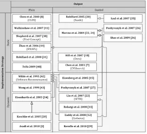
A particular type of automation isfeature-based configuration(FBC). FBC is an interactive process during which one or more stakeholders select and discard features to build a specific product. Traditionally, FBC systems support FM mod-elling, analysis and configuration. Currently, FBC techniques and tools facilitate the work of stakeholders in various ways, including: decision verification and propagation [22,38,47]; auto-completion [21,38]; scheduling of configuration tasks [20,23,35] and alternative representations of FMs [15,17].
FMs, and therefore FBC, are becoming increasingly large and complex. FMs are not only used to describe variability in software designs but also variability in different contexts, at different times in the development, and in different parts of the system [20,32,41,50,57]. Consequently, the list ofconcernsthat may be considered in an FM is very comprehensive [9,34,64] ranging from hardware description [41],
Separating Concerns in Feature Models: Retrospective and Support for Multi-Views 5
organizational structure [57], business to implementation details [50]. Concerns are related in numerous ways and there can be thousands of features whose legal combinations are governed by many and often complex rules.
Furthermore, it has been observed that maintaining a single large FM for the entire system may not be feasible [26,54]. With FMs being increasingly complex, describing various concerns of an SPL and handled by several stakeholders (or even different organizations), managing them with a large number of related features is intuitively a problem ofseparation of concerns(SoC) [11,61]. The sought benefits are indeed similar to the ones of software engineering disciplines, i.e., reduced complexity, improved reusability and simpler evolution [61]. A possible way to achieve SoC is then to rely on views, i.e., simplified representations of an FM tailored for a specific stakeholder, role, or task [36]. Views facilitate the decision-making process in that they only focus on those parts of the FM that are relevant for a given concern.
In this chapter, our goal is to give a clear overview of existing approaches in the field and state-of-the-art techniques for separating concerns in FMs. The intended audience is domain analysts or SPL practitioners working with FMs with an interest for FBC. In the first part of this chapter, we present a review of SoC in FMs. SoC has spawned much research on FM separation, composition and analysis. Here, we reuse some material presented in [36] and focus on concerns and their separation in FMs and FBC. We highlight the need for more modular and scalable techniques and revisit the concept of views. In the second part of this chapter, we focus on the creation of consistent views and the generation of alternative visualisations for FBC. We present and compare two techniques to synthesise visualisations of an FM. We also report on the progress made in developing tool support for SoC and multi-view FBC.
The rest of this chapter is organised as follows. Section 2 re-examines the basics of FMs and introduces our working example. Section3presents the general problem of SoC in FM and reviews existing works in the field. Section4describes a set of SoC techniques to specify, automatically generate and check multiple views. Section5presents the tools supporting it.
2
Background
2.1
Feature-Based Configuration
Schobbens et al. [59] defined a generic formal semantics for a wide range of FM dialects. In essence, an FMd is a hierarchy of features (typically a tree) topped by a root feature. An FM is informally defined as follows.
Definition 1 (FM (adapted from [59])). An FM d is a tuple .N; r; ;DE; ˚ / whereN denotes the set of features.r2Nthe root of the feature tree.WN!NN
6 A. Hubaux et al.
denotes the cardinalityhi::jiattached to a feature, wherei(resp.j) is the minimum (resp. maximum) number of children (i.e., features at the level below) required in a product (aka configuration). For convenience, common cardinalities are denoted by Boolean operators, as shown in Table1.DEN N denotes the decomposition edges, i.e., the parent–child relationship. Additional constraints that crosscut the tree (˚ 2B.N /) can also be added and are defined, without loss of generality, as a conjunction of Boolean formulae.
The semantics of an FM is the set of configurations (also called products), denotedd, where each configuration is a combination of selected features. The full syntax and semantics as well as benefits, limitations and applications of FMs are extensively discussed elsewhere [12,59].
FBC tools use FMs to pilot the configuration of customisable products. These tools usually render FMs in anexplorer-viewstyle [47,55], as shown in the upper part of Table1. The tick boxes in front of features are used to capture decisions, i.e., whether the features are selected or not. We now illustrate the FM abstract syntax more concretely on our working example.
2.2
Working Example
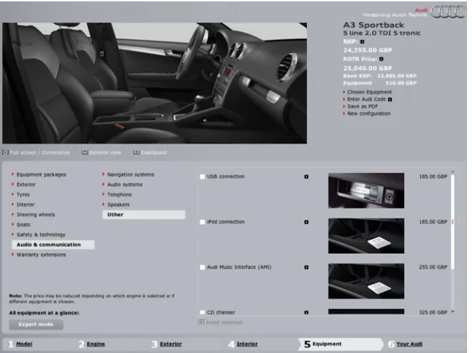
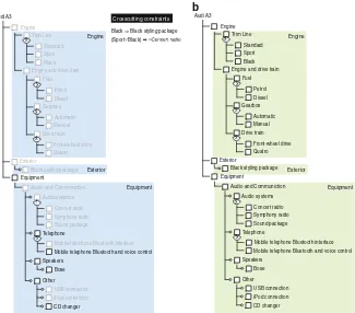
Audiis a German car manufacturer. Nowadays, Audi offers12different model lines, each available in different body styles, each broken down in different models. This paper will focus on theAudi A3, with thesportbackbody style. An example of its configurator in action is shown in Fig.1. The two FMs in Fig.2are samples reverse engineered from the car configurator1for the A3 and RS3 models.
Although similar, these models show very different options to customers. The features hidden by the configurator appear in light grey. This, however, does not indicate that the value of these features is not set. It rather means that customers
1Reverse engineered fromhttp://configurator.audi.co.uk/on January 20th, 2012. Some labels were shortened for conciseness.
Separating Concerns in Feature Models: Retrospective and Support for Multi-Views 7
Fig. 1 Screenshot of Audi A3 configurator
cannotmanuallyset their values. In Fig.2a for instance, none of theEnginefeatures are available. Yet, the RS3 has aQuatrodrive train and aPetrolengine. This practice resembles the inactivation of features in operating systems configurators such as those used for Linux and eCos [13]. The isolation of visible from hidden features is thus a first possible criterion to separate concerns.
The second criterion is determined by the steps in the configuration process. As Fig.1shows, the configuration follows a number of steps starting from1. Model, going through5. Equipment, and ending at6. Your Audi. This decomposition is illustrated in Fig.2by the coloured areas. In contrast to the first criteria, these views are used to progressively disclose the options.
The Audi configurator, like many others (e.g. Linux and eCos [66]), rely onad hocsolutions that usually do not come with a proof of completeness and correctness and can hardly be reused from one domain to the other. A general and formal foundation for separation of concerns in FBC is necessary. This paper proposes a retrospective on this SoC in FBC and discusses the complementary combination of views and slices to achieve flexible and reliable SoC. Without delving into formal developments, it provides a frame of reference to specify, verify and visualise concurrent concerns on an FM.
8 A. Hubaux et al. Mobile telephone Bluetooth and voice control
Speakers
Black Black styling package (Sport Black) Mobile telephone Bluetooth and voice control
Speakers
3
Concerns and Their Separation: Retrospective
A major limitation of current FM languages is that they are found not to scale well when applied to realistic SPLs. In real projects it has been reported that maintaining a single large FM for the entire system may not be feasible [26].
Firstly, FMs are increasingly larger with possibly thousands of features related by numerous complex constraints. As an extreme case, the variability model of Linux exhibits 6,000Cfeatures [60]. Secondly, various concerns of an SPL, handled by several stakeholders (or even different organizations), should be properly modelled and managed. As a result, FMs quickly become too complex to be understood and managed by practitioners. In FBC context, it is very hard for a practitioner to consider thousands of configuration options as a whole.
The principle of SoC points to an effective way to manage the size and complexity of FMs. On the one hand, several FMs may be originally separated and combined, for instance, when engineers describe the variability of modular systems (e.g., software components or services [5]), when independent suppliers
Separating Concerns in Feature Models: Retrospective and Support for Multi-Views 9
describe the variability of their different products in software supply chains [22,33], or when a multiplicity of SPLs must be combined [26,32]. On the other hand, it may be the intention of an SPL practitioner to modularise the variability description of the system according to different criteria or concerns such as external vs. internal variability [7,50,54], abstraction layers [41] or views tailored for a specific stakeholder [36].
The problem of SoC in FMs has been extensively reported in the literature, but there is no consensus on how best to separate and compose these concerns. In this paper, we focus on theseparation of concernproblem. This section highlights key achievements in this domain with a particular emphasis onviews, which have been repeatedly advocated as a means to solve scalability and configuration issues.
3.1
Variability Modelling
Dealing with real-world problems implies dealing with multiple stakeholders with different and often inconsistent perspectives. Viewpoint-based approaches have been around for nearly two decades and address exactly those issues. They mainly support the identification, structuring, reconciliation and co-evolution of heteroge-neous requirements [28,51]. They have been studied mostly by the requirements engineering (RE) community. They are more concerned with the identification and reconciliation of viewpoints than with the specification and generation of viewpoint-(or concern-) specific views on an artefact like the FM in our case. Viewpoint-based RE techniques are not specific to SPLE. Still, viewpoint-based techniques can be usedupstreamof variability modelling to help build a consistent FM from hetero-geneous viewpoints. More specific to variability modelling, Gr¨unbacher et al. [31] outline the challenges that arise when heterogeneous stakeholders are involved in the modelling of large FMs.
The identification of stakeholders is also a problem studied in RE [29]. We refer the reader to [30] for a general introduction to stakeholder identification and ways to structure and trace their contributions. Directly related to feature modelling, Bidian et al. [14] identify stakeholder profiles through the tasks appearing in goal models which are subsequently linked to the features realising them.
3.2
View Specification
Early attempts to manage the complexity of FMs [40,41] were mainly concerned with separating user-oriented from technical features. For this, simple techniques were used, namely annotation and layering of the FM, but those remained informal and were not used to generate views or for configuration. In OVM [53], a similar distinction was proposed between internal and external variability, but had the same limitations as the aforementioned approaches.
10 A. Hubaux et al.
Zhao et al. [67] group features according to stakeholder profiles and other typical concerns. A major limitation is that they do not display decomposition operators in views, which greatly simplifies the problem at the expense of completeness. Features in views are physically duplicated and mapped to features of the FM. The resulting links are represented as constraints between the views and the FM.
Researchers developed SoC techniques for FMs that reflect organisational structures and tasks. Reiser et al. [56] address the problem of representing and managing FMs in SPLs that are developed by several companies, as is common, for example, in the automotive industry. They propose to use several FMs and structure them hierarchically. This way, each of them can be managed separately by one of the partner companies. Local changes are then propagated to other FMs through the hierarchy. Hierarchical decomposition in SPLs was also studied by Thompson et al. [62], although not in relation to FMs.
Clarke et al. [18] introduce a formal theory of views for FMs, where a view is defined as a disjoint set of features andabstractions. An abstraction encapsulates a set of features hidden behind a label meaningful to the user. They formally define compatibility properties between views and their reconciliation, i.e., combination. To preserve the genericity of their mathematical model, the authors reason exclu-sively in terms of features independently of the structure and constraints imposed by the FM. As a result, they do not discuss the concrete specification, rendering and configuration of views on an FM.
3.3
Configuration
Reiser et al. [56] along with Mannion et al. [44] discuss how multiple views affect the structure of the FM and configuration with a particular focus on decision propagation and conflict resolution [44]. Unlike other approaches that only consider the selection/deselection of features, they address changes to the structure of views that are propagated back to the original FM. To resolve conflicts that can happen during the merge of concurrent changes, they propose a list of conflict resolution rules within views. They thus focus on resolving conflicts among changes to the content of the FM rather than conflicts between configuration decisions.
Batory et al. [10] have worked on multi-dimensional SoC where a dimension is a set of features addressing a particular concern. They use a so-called origami matrix to describe the relationships between features across the dimensions. Their approach does not aim to generate views but rather to compose features (described separately) along each dimension.
Czarnecki et al. [23] have introduced multi-level staged configuration as a way of organizing FBC as a sequence of stages. This idea was later formalised [20] and extended [35] to deal with arbitrarily complex configuration processes (not only purely sequential ones). Mendonc¸a et al. [46,48] suggest configuration spaces (similar to views) as a means to support collaborative product configuration. They also provide algorithms to automatically generate a configuration plan out of an FM
Separating Concerns in Feature Models: Retrospective and Support for Multi-Views 11
and a set of configuration spaces. Although these and related [50,63] approaches are automatable and readily applicable to configuration, they remain limited to a single “tyrannical” decomposition scheme [61] (e.g., stages or workflow activities) which must be decided in advance.
Over the years, various interactive FBC environments have been developed (e.g., [8,42,45,55]). Based on formal semantics, these tools use solvers (e.g., SAT, BDD and CSP) to propagate decisions throughout the FM and ensure the global consistency of the final product. Commercial FBC tools (e.g., [42,55]) also offer integration with popular modelling environments like IBM Rational or Simulink. Traditionally, FBC tools assume that there exists a single monolithic FM and do not account for configuration processes that are distributed among various stakeholders who have specific concerns and who intervene at different moments [46,48]. Without the appropriate support, FBC can become very cumbersome and error-prone, e.g., if a single stakeholder has to make decisions on behalf of all others [48].
4
Separating Concerns in Feature Models
4.1
Views
4.1.1 Basic Definition
Separating concerns requires the ability to specify the parts of the FM that are of interest and the person(s) who can configure it. In order to achieve this, the FM can be augmented with a setV of views, each of which consists of a set of features. Formally, amulti-view FMis defined as follows:
Definition 2 (Multi-view FM [36]). A multi-view FMmis a tuple.N; r; ;DE; ˚; V /whereV D fv1;v2; : : : ;vngis the multiset of views such that:
• N; r; ;DE; ˚conform to Definition1; • 8vi 2V vi N ^r2vi.
Therefore, for any concern that requires only partial knowledge of the FM, such as a profile, a view can be defined. We also consider that the root is part of each view.V is a multiset to account for duplicated sets of features.
4.1.2 View Specification
We distinguish between two ways of specifying views. Withextensional definitions, the features that appear in a view are enumerated, or tagged so as to indicate the view to which each of the features belongs. A drawback is that the process of enumerating and tagging can be time-consuming and error-prone without appropriate tool support.
12 A. Hubaux et al.
With intensional definitions, the features in a view are defined according to a query defined on the FM. For instance, the tree structure of the FM can be exploited by languages like XPath to specify the views. A major drawback of intensional definitions is that textual languages may not be as intuitive as graphical approaches for casual users. Furthermore, it is harder to maintain consistency between the FM and the textual expressions when the diagram evolves without proper tool support.
Having said that, extensional and intensional definitions can be used together in practice. Textual expressions corresponding to intensional specifications could be generated from a graphical view definition tool. Conversely, it is possible to generate feature tags from textual expressions and link them to the features in the expression. These links can then be used to trace changes from the FM back in the expression. This allows us to overcome the limitations of both extensional and intensional definitions. In the following discussions, we refer to features contained in views irrespective of the specification method.
4.1.3 View Coverage
An important property that should be guaranteed by an FBC system is that all configuration questions are eventually answered [20]. In a multi-view context, one may consider enforcing the following condition.
Definition 3 (Sufficient coverage condition [36]). For a viewvof a multi-view FMmthe sufficient coverage condition is:
[
v2V
vDN
Intuitively, this means that all the features appear in at least one view, hence no feature can be left undecided.2Although sufficient, this is not a necessary condition because some decisions can usually be deduced from others.
Anecessary conditioncan be defined in terms of propositional defineability [43]. It is necessary to ensure that the decisions on the features that do not appear in any view can be inferred from (i.e., arepropositionally defined by) the decisions made on the features that are part of the view. In the following definition,defines.F; f / denotes the propositional definably off byF.
Definition 4 (Necessary coverage condition [36]). For a viewvof a multi-view FMmthe necessary coverage condition is:
8f …[
v2V
v defines.[
v2V v; f /
2Note that the complete view coverage is usually assumed by multi-view approaches (e.g. [48]).
Separating Concerns in Feature Models: Retrospective and Support for Multi-Views 13
definescan be evaluated by translating the FM into an equivalent propositional formula (done in linear time [58]) and by applying the SAT-based algorithm described in [43]. Although this check is NP complete in theory, it is not expected to be a problem in practice, since SAT solvers can handle FMs with thousands of features.
Features inN nSv2Vvthat do not satisfy the above condition will have to be integrated in existing views, or extra constraints will have to be added to determine their value.
In application domains such as operating systems, features such as those used for calculating the boot entry to use are hidden from users [13] and may not be visible in any view. In such cases, the verification of the necessary condition determines whether the value of the hidden features can be derived from the features in the views.
However, in cases such as the Audi configurator (Sect.2.2), these two conditions are too strict. Assuming that a view only contains the features relevant to a customer, it will naturally not contain the hidden features. In this particular case, some hidden features might not be decided upon. Some existing configurators, such as the one of Linux, nullify these features. In this context, the necessary coverage condition has to be adapted such that one only checks features that are neither inSv2V vnor in the nullified features.
4.2
Visualisation
Although views are abstract, they have to be made concrete to be used during FBC. A concrete view is called avisualisation. A visualisation strives to find a compromise between not showing in a view features that do not belong to the view, and showing features that do not belong to the view but indirectly provide context for features that should be shown. In Fig.2, for instance, featureY is in the view (darker area), but its parent featureAis not.
To tackle this problem of view rendering, we have observed the practice of developers (see [37] for more details about the case study and our experience with PloneMeeting) and discussed with them alternative visualisations. Our discussions included the relative merits of the approaches suggested in [48,67], and the filtering mechanisms provided by tools such as pure::variants [55], and kernel configurators for operating systems (e.g.,xconfigfor Linux andconfigtoolfor eCos [27]). These tools provide simple filtering or search mechanisms that are similar to views on an FM. In these cases, a filter is a regular expression on the FM. Any feature matching the regular expression is displayed typically without any control on the location of the feature in the hierarchy. Interestingly, all these approaches produce purely graphical modifications (e.g., by greying out irrelevant features) whereas cardinalities are not recomputed.
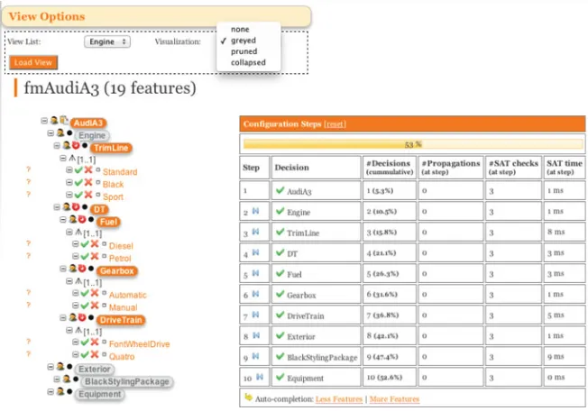
The main outcome of our investigation is a set of four complementary visual-isations offering different levels of details, as depicted in Fig.3. The darker area
14 A. Hubaux et al.
Fig. 3 Three alternative visualisations of FM views: greyed, pruned and slice/collapsed [36]
defines a specific view of the FM, called v. These views were built to present information on a need-to-know basis. The amount of information displayed can be regulated, while providing enhanced control over access rights. For instance, there is always a standardised configuration menu that can display the position of the feature in the hierarchy and hide unavailable options. On the other hand, in a critical application, features outside a view may have to be protected as trade secrets. Therefore, visualisations not only can provide convenient representations of a view, but they can also restrict the information a stakeholder can access.
Figure3illustrates the alternative visualisations of FM views we propose: • Thegreyedvisualisation is a mere copy of the whole FM except that the features
that do not belong to the view are greyed out (e.g.,A,B,DOandDB). Greyed features are only displayed but cannot be manually selected/deselected.
• In theprunedvisualisation, features that are not in the view are pruned (e.g.,B, DOandDB) unless they appear on a path between a feature in the view and the root, in which case they are greyed out (e.g.,A).
• In thecollapsedvisualisation, all the features that do not belong to the view are pruned. A feature in the view whose parent or ancestors are pruned is connected to the closest ancestor that is still in the view. If no ancestor is in the view, the feature is directly connected to the root (e.g.,Y andO).
• Theslicevisualisation is similar to thecollapsedvisualisation except that it takes cross-tree constraints into consideration. Consequently, decomposition operators might be altered to preserve the correctness of these constraints.
Generating visualisations, from an FM and a view, is a form of FM transfor-mation.
Definition 5 (View visualisation). The visualisation of a viewvis the transforma-tion of the original FM into a new FMdt
v D .Nvt; r; tv;DEtv; ˚ /, wheret, the type
of visualisation, can take one of four values:g (greyed),p(pruned),c(collapsed) ands(slice).
The greyed visualisation is the simplest case because there is no transformation beyond the greying of each featuref 62 v(i.e., dvg D d). The transformations
Separating Concerns in Feature Models: Retrospective and Support for Multi-Views 15
for the pruned and collapsed visualisations, on the other hand, filter nodes, remove dangling decomposition edges and adapt the cardinalities accordingly.
4.2.1 Pruned Visualisation
Nvp, the set of features in this visualisation, is the subset ofN limited to features that
are invor have a descendant inv. The definition usesDEC, the transitive closure ofDE. Based onNvp, we remove all dangling edges, i.e., those not inNvpNvpto
createDEpv.
Transformation 1 (Pruned visualisation [36]).
The transformations applied to the FM to generate the pruned visualisation are:
Nvp D fn2Njn2v_ 9f 2v.n; f /2DECg
DEp
v D fDE\.N
p
v Nvp/g
pv.f / D .mincardpv.f /;maxcardpv.f //
In order to compute the new cardinalitiespv.f /,mincardpv.f /andmaxcardpv.f /
are defined as follows:
mincardpv.f / D max.0; .f /:min jorphanspv.f /j/
maxcardpv.f / D min..f /:max;jchildren.f /j jorphanspv.f /j/
whereorphanspv.f / D children.f /nNvp i.e., the set of children of f that are
not inNvp..f /:minand.f /:maxrepresent the minimum and maximum values
of the original cardinality, respectively. For the minimum, the difference between the cardinality and the number of orphans can be negative in some cases, hence the necessity to take the maximum between this value and0. The maximum value is the maximum cardinality off ind if the number of children invis greater. If not, the maximum cardinality is set to the number of children that are inv.
4.2.2 Collapsed Visualisation The set of featuresNc
v of this visualisation is simply the set of features in v. The
consequence on DEcv is that some features have to be connected to their closest ancestor if their parent is not part of the view.
Transformation 2 (Collapsed visualisation [36]). The transformations applied to the FM to generate the collapsed visualisation are:
NvcDv
DEcvD f.f; g/jf; g2v^.f; g/2DEC^Àf02v..f; f0/2DEC^.f0; g/2DEC/g
cv.f /D.mincardcv.f /;maxcardcv.f //
16 A. Hubaux et al.
The computation of cardinalitiesc
v.f /is slightly more complicated than in the
pruned case. Formally,mincardcv.f /andmaxcardcv.f /are defined as follows:
mincardcv.f / D Pmin.f /:min.ms mincv.f //
maxcardcv.f / D Pmax.f /:max.ms maxcv.f //
where
ms mincv.f / D fmincardcv.g/jg2orphansvc.f /g ] f1jg2children.f /norphanscv.f /g ms maxcv.f / D fmaxcardcv.g/jg2orphansvc.f /g ] f1jg2children.f /norphanscv.f /g
The multisetsms mincv.f /andms maxcv.f /collect the cardinalities of the descen-dants off. The left part of the union3 recursively collects the cardinalities of the
collapsed descendants whereas the right side adds1 for each child that is in the view. The .f /:min minimum values of the multiset are then summed to obtain the minimum cardinality off. The maximum value is computed similarly.
4.2.3 Slice Visualisation
We revisit here a technique called slicing that, given an FM (typically large), produces a new, smaller FM containing only a subset of features of the input FM. We show that the slicing can be used to synthesize visualisations.
The overall idea behind FM slicing is similar to program slicing [65]. Program slicing has been successfully applied in computer programming and aims at simplifying or abstracting programs by focusing on selected aspects of semantics. Program slicing techniques usually proceed in two steps: the subset of elements of interest (e.g., a set of variables of interest and a program location), called the slicingcriterion, is first identified; then, aslice(e.g., a subset of the source code) is computed. In the context of FMs, we define the slicing criterion as a set of features considered to be pertinent by an SPL practitioner while the slice is a new FM (see Transformation3).
Slicing Semantics. The major preoccupation for an SPL practitioner is the legal combination of features (configurations) defined by an FM. The same observation applies when decomposing the FM into smaller concerns. We want to guarantee semantic properties of smaller parts, i.e., in terms of set of configurations. Nev-ertheless, several FMs, yet with different hierarchies, can represent a given set of configurations. Therefore, the semantics of the slicing operator is defined both in terms of set of configurations and feature hierarchy (see Transformation3). Transformation 3 (Slice visualisation [4]). We define slicing as an operation on FM, denoted ˘Ns
v .d / D d s
v where Nvs is a set of features, called the slicing
criterion, andds
v is a new FM, called the slice.
3]is the union on multisets.
Separating Concerns in Feature Models: Retrospective and Support for Multi-Views 17
The result of the slicing operation is a new FM,ds
v, such that:
• Feature hierarchy: Features of the hierarchy include the slicing criterion of the original FM while features are connected to their closest ancestor if their parent feature is not part of the slice FM. It corresponds to the feature hierarchy defined for the collapsed visualisation (see Transformation2).
• Configuration semantics: The valid configurations,ds
v, one could infer from a
slice are actually the valid configurations of the original FM, when looking only at the slicing criterion featuresNs
v. Formally, the projected4set of configurations
is defined asds
vDdjNs v.
It should be noted that the hierarchy of the slice FM corresponds to the hierarchy defined for the collapsed visualisation (see the right hand side of Fig.3). In the following, we will describe an algorithm to synthetize automatically such visualisations.
Automated Slice Synthesis. Our previous experience has shown that syntactic strategies have severe limitations to accurately represent a given set of configura-tions (as expected by Transformation3), especially in the presence of cross-tree constraints [2]. The same observation applies for the slicing operation so that we reason directly at thesemanticlevel. The key idea of the proposed algorithm is to(i) compute the propositional formula representing the projected set of configurations, and then to(ii)apply satisfiability techniques to construct a complete FM (including variability information and cross-tree constraints) using the formula. A major difference with previous works [24,60] that propose to synthetize FMs from propositional formulae is that the feature hierarchy of the resulting FM can be determined and computed (see Transformation3).
Formula Computation. Let ds
v D ˘Nvs .d /. The propositional formula s corresponding tods
v can be defined as follows:
s 9f1; f2; : : : fm0
wheref1; f2; : : : fm02.N nNvs/DNremovedandis the encoding ofd as a propo-sitional formula. The propopropo-sitional formulas is obtained frombyexistentially quantifyingout variables inNremoved. Intuitively, all occurrences of features that are
not present in any configuration ofds
v are removed by existential quantification5
in.
From Formula to FM. From the propositional formula s, several FMs can be synthesised [60]. In our case, though, we alreadyknowwhat the resulting hierarchy
4For two given setsAandB, we noteA
jBthe projection ofAonBsuch that:AjB 4
D fa0ja2 A^a0Da\Bg D fa\Bja2Ag
5Existential quantification is defined as the substitution of a Boolean variableftto True and False values. Formally:9ft Ddef jft_j Nf t wherejft(resp.j Nf t) denotes the assignment offtto True (resp. False) value in.
18 A. Hubaux et al.
is. Our algorithm exploits this information. We first compute the hierarchy, we then set the variability information (mandatory/optional, Xor and Or-groups) and finally the constraints (bi)-implies/excludes/others.
Mandatory and Feature Groups. At this step, all features, except root, are consid-ered optional. We compute the binary implication graph, notedBIGs, of the formula s overNvs.
BIGsis a directed graphG D.V; E/formally defined as:
V D Ns E D f.fi; fj/js ^ fi ) fjg
We useBIGsto identify biimplications and thus set mandatory features together with their parents. For feature groups, we reuse the prime implications method proposed in [24], so that we can identify Or- and Xor-groups. An important issue is that a feature may be candidate to several feature groups (which is not allowed by FMs). Therefore some feature groups are dismissed so that FMs are well formed. We use the original FM to retrieve initial feature groups (see details in [1]). Constraints. The set of implies constraints can be deduced by removing edges of BIGs that are already expressed (e.g., parent–child relations). For the purpose of conciseness, some implies constraints can be transformed into equivalence relations (e.g.,A ) B^B ) Acan be transformed intoA , B). Similarly, excludes constraints are produced by computing the binary exclusion graph of s over Ns
v. Excludes constraints that were not chosen to be represented as an Xor-group
are added. When adding constraints, we control that the constraint is not already induced by the FM. At this end, it should be noted that the FM may still be an over approximation ofs.6Using standard propositional logics techniques, we can
calculate the complement between the current set of configurations represented by the FM and the expected set of configurations of the slice FM. The complement can be recovered, for instance, as a conjunction of propositional constraints.
4.2.4 Properties and Comparison
We now discuss properties of the slicing technique and the transformations described above regarding their ability to produce visualisations.
Semantic Preservation. It is important to demonstrate that the visualisations preserve a form of semantic equivalence with the original FM. We define the semantic equivalence in terms of the set of configurations characterised by the original FM and the projected set of configuration characterised by the collapsed visualisation.
6In [24], the authors characterised the limited expressiveness of FMs compared to propositional logic.