Open Geospatial Consortium
Publication Date: 2015-11-18 Approval Date: 2015-08-27 Posted Date: 2015-07-21
Reference number of this document: OGC 15-058
Reference URL for this document: http://www.opengis.net/doc/PER/tb11-symbology-mediation
Category: Public Engineering Report
Editor(s): Stephane Fellah
OGC Testbed-11 Symbology Mediation Engineering Report
Copyright © 2015 Open Geospatial Consortium.
To obtain additional rights of use, visit http://www.opengeospatial.org/legal/.
Warning
This document is not an OGC Standard. This document is an OGC Public Engineering Report created as a deliverable in an OGC Interoperability Initiative and is not an official position of the OGC membership. It is distributed for review and comment. It is subject to change without notice and may not be referred to as an OGC Standard. Further, any OGC Engineering Report should not be referenced as required or mandatory technology in procurements.
Document type: OGC® Engineering Report Document subtype: NA
License Agreement
Permission is hereby granted by the Open Geospatial Consortium, ("Licensor"), free of charge and subject to the terms set forth below, to any person obtaining a copy of this Intellectual Property and any associated documentation, to deal in the Intellectual Property without restriction (except as set forth below), including without limitation the rights to implement, use, copy, modify, merge, publish, distribute, and/or sublicense copies of the Intellectual Property, and to permit persons to whom the Intellectual Property is furnished to do so, provided that all copyright notices on the intellectual property are retained intact and that each person to whom the Intellectual Property is furnished agrees to the terms of this Agreement.
If you modify the Intellectual Property, all copies of the modified Intellectual Property must include, in addition to the above copyright notice, a notice that the Intellectual Property includes modifications that have not been approved or adopted by LICENSOR. THIS LICENSE IS A COPYRIGHT LICENSE ONLY, AND DOES NOT CONVEY ANY RIGHTS UNDER ANY PATENTS THAT MAY BE IN FORCE ANYWHERE IN THE WORLD.
THE INTELLECTUAL PROPERTY IS PROVIDED "AS IS", WITHOUT WARRANTY OF ANY KIND, EXPRESS OR IMPLIED, INCLUDING BUT NOT LIMITED TO THE WARRANTIES OF MERCHANTABILITY, FITNESS FOR A PARTICULAR PURPOSE, AND NONINFRINGEMENT OF THIRD PARTY RIGHTS. THE COPYRIGHT HOLDER OR HOLDERS INCLUDED IN THIS NOTICE DO NOT WARRANT THAT THE FUNCTIONS CONTAINED IN THE INTELLECTUAL PROPERTY WILL MEET YOUR REQUIREMENTS OR THAT THE OPERATION OF THE INTELLECTUAL PROPERTY WILL BE
UNINTERRUPTED OR ERROR FREE. ANY USE OF THE INTELLECTUAL PROPERTY SHALL BE MADE ENTIRELY AT THE USER’S OWN RISK. IN NO EVENT SHALL THE COPYRIGHT HOLDER OR ANY CONTRIBUTOR OF
INTELLECTUAL PROPERTY RIGHTS TO THE INTELLECTUAL PROPERTY BE LIABLE FOR ANY CLAIM, OR ANY DIRECT, SPECIAL, INDIRECT OR CONSEQUENTIAL DAMAGES, OR ANY DAMAGES WHATSOEVER RESULTING FROM ANY ALLEGED INFRINGEMENT OR ANY LOSS OF USE, DATA OR PROFITS, WHETHER IN AN ACTION OF CONTRACT, NEGLIGENCE OR UNDER ANY OTHER LEGAL THEORY, ARISING OUT OF OR IN CONNECTION WITH THE IMPLEMENTATION, USE, COMMERCIALIZATION OR PERFORMANCE OF THIS INTELLECTUAL PROPERTY. This license is effective until terminated. You may terminate it at any time by destroying the Intellectual Property together with all copies in any form. The license will also terminate if you fail to comply with any term or condition of this Agreement. Except as provided in the following sentence, no such termination of this license shall require the termination of any third party end-user sublicense to the Intellectual Property which is in force as of the date of notice of such termination. In addition, should the Intellectual Property, or the operation of the Intellectual Property, infringe, or in LICENSOR’s sole opinion be likely to infringe, any patent, copyright, trademark or other right of a third party, you agree that LICENSOR, in its sole discretion, may terminate this license without any compensation or liability to you, your licensees or any other party. You agree upon termination of any kind to destroy or cause to be destroyed the Intellectual Property together with all copies in any form, whether held by you or by any third party. Except as contained in this notice, the name of LICENSOR or of any other holder of a copyright in all or part of the Intellectual Property shall not be used in advertising or otherwise to promote the sale, use or other dealings in this Intellectual Property without prior written authorization of LICENSOR or such copyright holder. LICENSOR is and shall at all times be the sole entity that may authorize you or any third party to use certification marks, trademarks or other special designations to indicate compliance with any LICENSOR standards or specifications.
This Agreement is governed by the laws of the Commonwealth of Massachusetts. The application to this Agreement of the United Nations Convention on Contracts for the International Sale of Goods is hereby expressly excluded. In the event any provision of this Agreement shall be deemed unenforceable, void or invalid, such provision shall be modified so as to make it valid and enforceable, and as so modified the entire Agreement shall remain in full force and effect. No decision, action or inaction by LICENSOR shall be construed to be a waiver of any rights or remedies available to it.
Contents
Page1 Introduction ... 1
1.1 Scope ... 1
1.2 Document contributor contact points ... 1
1.3 Revision history ... Error! Bookmark not defined. 1.4 Future work ... 1
1.5 Foreword ... 1
2 References ... 2
3 Terms and definitions ... 2
4 Conventions ... 4
4.1 Abbreviated terms ... 4
4.2 UML notation ... 5
5 ER Topic overview ... 6
6 Symbology in Emergency Management ... 8
6.1 Overview ... 8
6.2 FGDC HSWG Emergency Management Symbology ... 9
6.3 Canadian Emergency Management Symbology ... 10
7 Review of existing Portrayal standards ... 12
7.1 ISO 19117 ... 12
7.2 SLD ... 12
7.3 SE ... 13
7.4 KML ... 13
8 Incident Ontologies ... 13
8.1 ADP LEAPS Model ... 13
8.2 Core Incident Model ... 14
8.3 Incident model and data for demonstration ... 16
9 Portrayal Ontologies ... 19
9.1 Overview ... 19
9.2 Design Approach ... 21
9.2.1 Minimal ontological commitment ... 21
9.2.2 Modularization of ontologies ... 21
9.2.3 Reusability of ontologies ... 22
9.2.4 Understandability ... 22
9.3 Style Ontology ... 22
9.3.1 Style ... 23
9.3.2 PortrayalRuleSet ... 25
9.3.3 PortrayalRule ... 26
9.4 Symbology Ontology ... 29
9.5.2 Font, FontFamily and Foundry ... 35
9.6 Portrayal Catalog Ontology ... 36
10 Portrayal Encoding ... 37
10.1 HSWG Portrayal Encoding ... 37
10.2 EMS Portrayal Encoding ... 37
11 Semantic Mediation ... 38
11.1 Introduction ... 38
11.2 Review of existing approaches ... 38
11.2.1 EDOAL ... 39
11.2.2 Rule Interchange Format ... 40
11.2.3 SPIN ... 41
11.2.4 Topbraid SPIN Map ... 42
11.3 Approach used for testbed ... 43
11.4 SPARQL Extensions ontology ... 44
11.4.1 Modeling Query in RDF ... 44
11.4.2 Meta-modeling vocabulary ... 45
11.5 Semantic Mediation Ontology ... 57
11.5.1 Alignment ... 57
11.6 Extensions functions to SPARQL ... 60
11.6.1.1 Examples ... 61
11.6.2 geosparql:eval ... 64
12 Implementations ... 64
12.1 Image Matters Semantic Mediation Service ... 64
12.1.1 Architecture ... 65
12.1.2 REST API Overview ... 65
12.1.3 Endpoint: /functions ... 66
12.1.9.1 HTTP Get Request ... 79
12.1.9.2 Response ... 79
12.1.9.3 Example ... 79
12.1.9.4 HTTP Post Request ... 82
12.2 Image Matters Semantic Portrayal Service ... 82
12.2.1 Architecture overview ... 82
12.2.2 REST API Overview ... 82
12.2.4.3 Examples ... 84
12.2.5 Endpoint: /sparql ... 87
12.2.5.1 Request ... 87
12.2.5.2 Response ... 87
12.2.5.3 Examples ... 87
12.3 Envitia Portrayal Service ... 91
12.4 Geomatys SLD Producer WPS ... 93
12.4.1 Use Case 1 : Envitia Server ... 95
12.4.2 Use case 2 : ImageMatters Server ... 101
12.5 WFS Sources ... 102
12.6 FPS and Client ... 102
13 Challenges encountered ... 104
14 Recommendation for future works ... 105
Annex A Portrayal Ontologies ... 107
Annex B Semantic Mediation Ontologies ... 108
Bibliography ... 110
Figures
PageFigure 1: HSWG Emergency Symbology Samples 9
Figure 2: EMS Classification Structure 10
Figure 3: Canadian EMS Symbols and taxonomy 11
Figure 4: Core incident ontology model 15
Figure 5: Semantic layer with adapters to the core incident model and derived profiles 16
Figure 6: SFPD Incident samples from SF OpenData 17
Figure 7: Portrayal Microtheories 20
Figure 8 Style Model Overview 23
Figure 9 Symbology Model Overview 30
Figure 10: Use of SPIN Functions for Model transformations 42
Figure 11 Topbraid SPINMap UI 43
Figure 12 Semantic Mediation Service Architecture 65
Figure 13 SPARQL Client response 89
Figure 14 FCU Map Client 103
Tables
PageTable 1 Namespace mapping for Portrayal Microtheories ... 21
Table 2: Style properties ... 23
Table 3 PortrayalRuleSet properties ... 25
Table 4 PortrayalRule properties ... 26
Table 5 PortrayalRuleCondition Properties ... 27
Table 6 SymbolSet Properties ... 30
Table 7 Symbol Properties ... 31
Table 8 SymbolDefinition Properties ... 33
Table 9 SymbolComponent properties ... 34
Table 10 ExternalGraphic properties ... 35
Table 11 Font properties ... 35
Table 12 FontFamily Properties ... 36
Table 13 Namespace mapping for semantic mediation microtheories ... 43
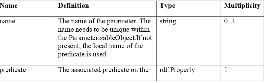
Table 14 Query Properties ... 44
Table 15 Parameter properties ... 45
Table 16 Function Properties ... 47
Table 17 FunctionLibrary properties ... 49
Table 18 MappingType Properties ... 49
Table 19 Query Tempalte properties ... 54
Table 20 AskTemplate properties ... 54
Table 21 Construct Template properties ... 55
Table 22 SelectTemplate properties ... 55
Table 23 SPARQLRule Properties ... 56
Table 24 RuleLibrary Properties ... 56
Table 25 Semantic Mediation Service REST API Summary ... 65
Table 26 Query Parameters for /functions endpoint ... 67
Table 27 Query parameters for /mappings/types endpoint ... 72
Table 28 Query parameters for /alignments/sparql endpoint ... 73
Table 29 Query Parameters for /alignments/instances endpoint ... 74
Table 30 Query parameters for /alignments/{id}/mediator endpoint ... 79
Table 31 Portrayal Service REST API Summary ... 82
Abstract
This OGC® Engineering Report (ER) summarizes the approaches, findings and the results of the Symbology Mediation sub-thread activities of the OGC Testbed-11 Cross
Community Interoperability (CCI) Thread. The ER:
Provides an overview of existing standards relevant to symbology mediation, Outlines the approaches adopted during the testbed,
Describes the conceptual models and services developed during the testbed to address semantic mediation and portrayal of feature information related to Emergency Management and to some extent to the Aviation domain.
Business Value
This Engineering Report proposes a solution to improve semantic interoperability in the following areas:
Incident management in the context of Emergency Management, Law Enforcement and Public Safety.
Semantic mediation
Portrayal of features using Linked Data standards.
Keywords
Testbed-11
Symbology Mediation
1 Introduction
1.1 Scope
This Engineering Report (ER) discusses the implementation of the models and services associated to perform semantic mediation and symbology portrayal. The report also discusses interoperability and standards gaps identified during the testbed and provides recommendations for future work.
1.2 Document contributor contact points
All questions regarding this document should be directed to the editor or the contributors:
Name Organization
Stephane Fellah Image Matters LLC
Gobe Hobona Envitia
Frederick Houbie Geomatys
1.3 Future work
For recommendations on future work please refer to section 14. 1.4 Foreword
Attention is drawn to the possibility that some of the elements of this document may be the subject of patent rights. The Open Geospatial Consortium shall not be held
responsible for identifying any or all such patent rights.
2 References
The following documents are referenced in this document. For dated references, subsequent amendments to, or revisions of, any of these publications do not apply. For undated references, the latest edition of the normative document referred to applies. OGC 05-078r4, OGC® Styled Layer Descriptor Profile of the Web Map Service Implementation Specification
OGC 05-077r4, OpenGIS Symbology Encoding Implementation Specification OGC 07-147r2, OGC KML
ISO 19117:2012, Geographic Information – Portrayal
OGC 11-052r4, OGC GeoSPARQL –A Geographic Query Language for RDF Data OGC 05-110, Feature Portrayal Service
OGC 11-063r6, OWS-8 CCI Semantic Mediation Engineering Report OGC 12-103r3, OWS-9 CCI Semantic Mediation Engineering Report OGC 14-049, Testbed 10 OWS CCI Ontology Engineering Report
OGC 14-106. Unified Geo-data Reference Model for Law Enforcement and Public Safety OGC-15-054 Implementing Linked Data and Semantically Enabling OGC Services Engineering Report
In addition to this document, this report includes several OWL Ontology Document files referred in Annex A and Annex B.
3 Terms and definitions
For the purposes of this report, the definitions specified in Clause 4 of the OWS Common Implementation Standard [OGC 06-121r3] shall apply. In addition, the following terms and definitions apply.
3.1
feature
3.2
interoperability
capability to communicate, execute programs, or transfer data among various functional units in a manner that requires the user to have little or no knowledge of the unique characteristics of those units [ISO 19119]
3.3
map
pictorial representation of geographic data
3.4
model
abstraction of some aspects of a universe of discourse [ISO 19109]
3.5
ontology
a formal specification of concrete or abstract things, and the relationships among them, in a prescribed domain of knowledge [ISO/IEC 19763]
3.6
portrayal
portrayal presentation of information to humans [ISO 19117]
3.7
semantic interoperability
the aspect of interoperability that assures that the content is understood in the same way in both systems, including by those humans interacting with the systems in a given context
3.8
semantic mediation
transformation from one or more datasets into a dataset based on a different conceptual model.
3.9
symbol
a bitmap or vector image that is used to indicate an object or a particular property on a map.
3.10
symbology encoding
style description to apply to the digital features being rendered
3.11
syntactic interoperability
4 Conventions
4.1 Abbreviated terms
CAP Common Alert Protocol
CCI Cross Community Interoperability E&DM Emergency and Disaster Management EDXL Emergency Data Exchange Language
ER Engineering Report
FPS Feature Portrayal Service
GML Geography Markup Language
HTML HyperText Markup Language
IMS Incident Management System
JSON-LD JavaScript Object Notation for Linked Data LEAPS Law Enforcement and Public Safety
NIEM National Information Exchange Model OGC Open Geospatial Consortium
OWL Web Ontology Language
OWS-8 OGC Web Services Initiative, Phase 8 OWS-9 OGC Web Services Initiative, Phase 9
RDF Resource Description Framework
SDI Spatial Data Infrastructure
SE Symbology Encoding
SLD Style Layer Descriptor
SVG Scalable Vector Graphics
URI Unique Resource Identifier
URL Uniform Resource Locator
URL Uniform Resource Name
WFS Web Feature Service
WKT Well Known Text
WMS Web Map Service
4.2 UML notation
5 ER Topic overview
Incident management plays a crucial role in many application domains including Homeland Security, Law Enforcement and Public Safety (LEAPS), and Emergency and Disaster Management (E&DM). An Incident Management System (IMS) needs to facilitate rapid, agile and effective engagement of first responders at national, state and local jurisdictional levels to respond to emergency incidents that may pose an immediate security threat to human life and/or the flow of commerce. The current systems face the following challenges.
Y Analysts and operators need to quickly triage, fuse, connect dots, detect patterns, infer insights, and make sense of the flow of incident information to get an unambiguous Common Operational Picture using symbology that makes sense to the users.
Y Users need to integrate and interpret incidents, observations, mutual aid requests, alerts, symbologies, taxonomies, etc. generated across a agency, multi-jurisdictional spectrum.
Y There is limited interoperability between agencies due to different protocols, taxonomies, models and symbolic representations (stovepipes are still there!). The current data-centric implementations are mainly based on syntactic and structural approaches and thus imposes a huge cognitive burden on the users to make sense of the large volume and varieties of information.
Data model standardization relies upon homogeneous data description and organization. This imposes strict adherence to a standard that is defined at the syntactic-schematic level. Achieving consensus in definition of the data model is difficult and the final model is less flexible. Modelers struggle between producing simple models where it is easier to gain consensus but harder to achieve desired business reality versus those seeking richer models that are closer to reality but have unwanted complexity.
Data-centric approaches (using for example XML Schema, or JSON) increase the chance for multiple interpretations and misinterpretations of data. Data interpretation requires knowledge of the semantics (e.g., meanings, significance, relevance, etc.) and
Resource Description Framework (RDF) which provides the core model for representing data in the form of a semantic graph composed of triples (W3C standard);
RDF Schema which provides a simple vocabulary to define classes and properties (W3C standard);
Web Ontology Language (OWL) which provides a more expressive vocabulary to define ontologies than RDF Schema (W3C standard); and
SPARQL Protocol and RDF Query Language (SPARQL) defines a query language for RDF data, analogous to the Structured Query Language (SQL) for relational databases (W3C standard).
Decentralized model extensions can be accommodated without adversely affecting the existing information infrastructure. Using these standards, a set of ontologies were developed during this testbed to represent incidents, portrayal information and semantic mediation mappings.
This ER is structured the following way.
Provides an overview about symbologies in E&DM, with a focus on two particular symbologies that were used in this testbed: the FGDC HSWG
Emergency Management Symbology and the Canadian Emergency Management Symbology.
Provide a review of the existing standards related to symbology that were taken in account in the design of the portrayal ontologies.
A review of incident models.
Describe in detail the Portrayal Ontologies designed and implemented during this testbed. We show how we encoded the HSWG EMS and Canadian EMS
symbology using these ontologies.
Introduce ontologies to support semantic mediation. The first ontology introduces a number of extensions to SPARQL to represent functions, rules, templates, queries in a Linked Data form. The second ontology is used to define semantic alignment between two ontologies.
Illustrate how these ontologies are used to implement semantic mediation between two simple incident models.
We end the ER document with a summary of challenges encountered during the testbed and the recommendations for future work.
6 Symbology in Emergency Management
6.1 Overview
A plethora of symbols and symbol schemes exist. However, despite the large number of initiatives targeting exactly such a standardized set, very few standardized sets can be found. Many of those initiatives date back to the first decade 2000-2009 and have failed to become widely accepted and applied mapping symbol standards.
There are various Symbology Best Practices available for Law Enforcement and Public Safety (LEAPS) used in the context of Emergency Management.
US FGDC ANSI 415-2006 INCITS Homeland Security Map Symbol Standard Canadian Emergency Management Symbology (EMS)
United Nations Office of Coordination on Humanitarian Affairs (UN-OCHA), which has created a set of 500 freely available humanitarian icons to help relief workers present emergency and crisis-related information quickly and simply Portuguese Disaster Response Map Symbols (DRMS) project, an effort to create a
standard set of symbols that may aid disaster managers and responders to create efficient maps
Australasian All-Hazards Symbology, developed by the Intergovernmental Committee on Surveying and Mapping (ICSM) and the Victoria-based company Spatial Vision
The European INDIGO project Emergency 2D/3D Symbology Reference World Meteorological Organization (WMO) Intergovernmental Oceanographic
Commission efforts on map symbol standardization
6.2 FGDC HSWG Emergency Management Symbology
The US Federal Geographic Data Committee Homeland Security Working Group (FGDC HSWG) symbology set, standardized by the American National Standards Institute (ANSI), divides symbols into four categories:
Incidents: cause of action or source of disaster;
Natural events: phenomenon created by naturally occurring conditions; Infrastructure: basic facilities, services and installations needed for the
functioning of a community; and
Operations: capabilities or resources available during or implemented due to an emergency.
Borders and patterns around these shapes are used to visually classify the symbols into their respective groups. The FGDC HSWG Emergency Management Symbology is designed in black and white and uses TrueType fonts for the icons.
Figure 1: HSWG Emergency Symbology Samples
6.3 Canadian Emergency Management Symbology
The Canadian Emergency Mapping Symbology (EMS) is designed to be used in both single and multi-agency emergency mapping applications to facilitate interoperability and situational awareness. The user community consists of federal, provincial, regional and local organizations involved in the management of major events, disasters, and other incidents where emergency help and security are needed. From a command and control perspective, which includes the military and many civilian organizations, such
occurrences are referred to as incidents. Some civilian agencies though have preferred the term event instead. As used by EMS, the terms incident and event are interchangeable. In addition to incidents, an understanding of the overall picture describing an emergency requires knowledge of infrastructures and operations. These terms are widely accepted, and consequently are used in EMS as well.
A symbology includes a set of symbol definition. As important, symbology also includes a classification of the entities under consideration. A four level, hierarchical taxonomy is used here. At the highest level, all entities fall in the EMS domain. Incident,
infrastructure and operation are considered as categories within that domain, as are aggregate and other. Other domains may exist with other categories. Each category is subdivided further to form a set of Tier 1 classes; each of these in turn is broken down further to create Tier 2 classes. A diagram showing the structure of the classification is shown in Figure 2: EMS Classification Structure
Figure 2: EMS Classification Structure
The classification can also be represented in text by a simple dot notation: Tier 1 entity: domain.category.tier1
Figure 3: Canadian EMS Symbols and taxonomy
For this project, we manually encoded the EMS Incident taxonomy using SKOS encoding. We then performed a manual mapping from the EMS concepts to HSWG concepts using SKOS mapping properties (skos:exactMatch, skos:closeMatch, skos:broaderMatch,…).
Here a sample of the mapping
@prefix : <http://www.opengis.net/taxonomy/ems-hswg_mapping#> . @prefix ems: <http://www.opengis.net/taxonomy/ems#> .
@prefix incidents: <http://www.fgdc.gov/HSWG/taxonomy/incidents#> .
@prefix natural-events: <http://www.fgdc.gov/HSWG/taxonomy/natural-events#> . @prefix owl: <http://www.w3.org/2002/07/owl#> .
@prefix rdf: <http://www.w3.org/1999/02/22-rdf-syntax-ns#> . @prefix rdfs: <http://www.w3.org/2000/01/rdf-schema#> . @prefix skos: <http://www.w3.org/2004/02/skos/core#> . @prefix spin: <http://spinrdf.org/spin#> .
@prefix xsd: <http://www.w3.org/2001/XMLSchema#> .
.
<http://www.opengis.net/taxonomy/ems#ems.incident.airQuality> skos:broadMatch incidents:Incident ;
.
<http://www.opengis.net/taxonomy/ems#ems.incident.civil.civilDemonstration> skos:exactMatch incidents:CivilDemonstrations ;
.
<http://www.opengis.net/taxonomy/ems#ems.incident.civil.civilDisplacedPopulation> skos:exactMatch incidents:CivilDisplacedPopulation ;
.
<http://www.opengis.net/taxonomy/ems#ems.incident.civil.civilEmergency> skos:broadMatch incidents:CivilDisturbanceIncident ;
.
<http://www.opengis.net/taxonomy/ems#ems.incident.civil.civilRioting> skos:exactMatch incidents:CivilRioting ;
..
<http://www.opengis.net/taxonomy/ems#ems.incident.animalHealth.animalFeed> skos:broadMatch incidents:Incident ;
.
<http://www.opengis.net/taxonomy/ems#ems.incident.aviation> skos:exactMatch incidents:AirIncident ;
.
<http://www.opengis.net/taxonomy/ems#ems.incident.aviation.aircraftCrash> skos:broadMatch incidents:AirAccident ;
.
7 Review of existing Portrayal standards
A number of existing standards related to Portrayal were considered during this testbed to help define an ontology.
7.1 ISO 19117
ISO 19117:2012 specifies a conceptual schema for describing symbols, portrayal functions that map geospatial features to symbols, and the collection of symbols and portrayal functions into portrayal catalogues. This conceptual schema can be used in the design of portrayal systems. 19117 allows feature data to be separate from portrayal data, permitting data to be portrayed in a dataset independent manner.
7.2 SLD
and software to be able to control the visual portrayal of the geospatial data. The ability to define styling rules requires a styling language that the client and server can both understand. The OpenGIS® Symbology Encoding Standard (SE) provides this language, while the SLD profile of WMS enables application of SE to WMS layers using
extensions of WMS operations. Additionally, SLD defines an operation for standardized access to legend symbols.
7.3 SE
This OGC standard defines Symbology Encoding, an XML language for styling information that can be applied to digital Feature and Coverage data. This document is together with the Styled Layer Descriptor Profile for the Web Map Service
Implementation Specification the direct follow-up of Styled Layer Descriptor
Implementation Specification 1.0.0. The old specification document was split up into two documents to allow the parts that are not specific to WMS to be reused by other service specifications.
7.4 KML
KML is an XML language focused on geographic visualization, including annotation of maps and images. Geographic visualization includes not only the presentation of
graphical data on the globe, but also the control of the user's navigation in the sense of where to go and where to look.
From this perspective, KML is complementary to most of the key existing OGC
standards including GML (Geography Markup Language), WFS (Web Feature Service) and WMS (Web Map Service). Currently, KML 2.2 utilizes certain geometry elements derived from GML 2.1.2. These elements include point, line string, linear ring, and polygon.
8 Incident Ontologies
8.1 ADP LEAPS Model
In 2014, the OGC published a best practice document providing an overview of the Unified Geo-data Reference Model for Law Enforcement and Public Safety (Unified Model) [OGC 14-106]. The Unified Model was originally developed by the GIS Center for Security (GIS CS), Abu Dhabi Police. The GIS CS was initiated based on a UAE Ministry of Interior issued decree to establish GIS CS with the core mission: “To geo-enable police services and applications using International standards and best practices.” In 2010, the GIS SC initiated a program to develop a Standardized GIS Environment (SGA). Part of this effort was to define and implement a standard data model for sharing Law Enforcement and Public Safety data.
world, there are many aspects of the domain such as incident location that are common across organizations. However, currently there is no data model best practice for the Law Enforcement community to use as a reference for these common information elements. The Reference Model described in the referenced diagrams in the document is provided as an exemplar and a starting point to help facilitate greater commonality and
interoperability between organizations. As it is common within this law enforcement domain, policing agencies will not utilize any reference model until it has been deemed a best practice. Upon acceptance the expectation is that modifications and enhancements will occur to meet the needs of a wider, more global population.
This best practice is not meant to compete or replace existing standards such as the NIEM (National Information Exchange Model) standard. The NIEM emphasizes data exchange between organizations typically within the US, and is based on XML, which reflects only a small subset of the information of interest to a full data model.
For this testbed, we analyzed only a subset of the unified reference model that relates to incident modeling and took it in account to refine the core Incident Ontology initiated during the OGC testbed 10. Overall the Incident ontology proposed in OWS-10 was consistent with the incident model of Unified Reference Model for LEAPS and could easily accommodate the specificities related to LEAPS by extending the proposed core Incident Ontology described in the next section.
Based on the analysis, we concluded that the unified reference model for LEAPS can be used to derive a set of foundational ontologies that serve as the basis for interoperability throughout LEAPS domain. These ontologies should be built upon a set of core OGC’s Geospatial Ontologies and take also in account other standards such as NIEM, EDXL and CAP. They should define the minimum-essential core set of concepts, properties and relationships for the LEAPS community. The LEAPS ontologies must be designed to accommodate any jurisdiction/mission profile specific information (taxonomies, specialized concepts and relationships), using the built-in extension mechanisms of OWL.
8.2 Core Incident Model
of core ontologies (spatial, temporal, identifier, event, SKOS) to provide a coherent model for geospatial reasoning on incidents.
Figure 4 gives an overview of the Incident Ontology Model. Incidents are based on the Event ontology defined in the Core Geospatial Ontologies.
Figure 4: Core incident ontology model
The core Incident Model can be extended using the built-in mechanism in OWL to add specific information used within an application domain or jurisdiction, thus becoming specialized profile of the core Incident model. Existing standards based on syntactic and schematic standards (NIEM, EDXL, NDEX,…) can be integrated in Semantic Incident Management Systems by the use of adapters converting the standard to an RDF
Figure 5: Semantic layer with adapters to the core incident model and derived profiles
8.3 Incident model and data for demonstration
Figure 6: SFPD Incident samples from SF OpenData
The data were exported in CSV format and the values of category of the incident were replaced with concepts from the HSWG EMS taxonomy in order to leverage the SKOS encoding of HSWG. We defined intentionally two different incident models to exercise the semantic mediation of taxonomies and ontologies.
Here a sample of a HSWG Incident using the HSWG EMS Taxonomy. @prefix ks: <http://www.usersmarts.com/ont/2005/06/ks#> .
@prefix spatial: <http://www.opengis.net/ont/spatial#> .
@prefix hswg: <http://www.opengis.net/testbed11/ont/incident/hswg#> . @prefix rdfs: <http://www.w3.org/2000/01/rdf-schema#> .
@prefix geosparql: <http://www.opengis.net/ont/geosparql#> . @prefix time: <http://www.knowledgesmarts.com/ontology/time#> . @prefix evt: <http://www.knowledgesmarts.com/ontologies/event#> . @prefix xsd: <http://www.w3.org/2001/XMLSchema#> .
@prefix owl: <http://www.w3.org/2002/07/owl#> .
@prefix wgs84: <http://www.w3.org/2003/01/geo/wgs84_pos#> . @prefix place: <http://www.knowledgesmarts.com/ontologies/place#> . @prefix skos: <http://www.w3.org/2004/02/skos/core#> .
@prefix evt-type: <http://www.smartrealm.com/ct/types/events#> .
@prefix ptype: <http://www.knowledgesmarts.com/ontologies/place/types#> .
@prefix incident: <http://www.opengis.net/ont/domain/emergency/police/incident#> .
<http://ows.usersmarts.com/ldapp/ows11/demo/ems/sfpd/incidents/11616059406244> a hswg:HSWGIncident ;
hswg:city "San Francisco" ; hswg:incidentNumber "116160594" ;
hswg:incidentTime "03:00:00"^^xsd:time ;
hswg:incidentType <http://www.fgdc.gov/HSWG/taxonomy/incidents#Looting>; hswg:location [ a wgs84:Point , geosparql:Point ;
geosparql:asWKT "POINT (-122.4106935 37.77302471)"^^geosparql:wktLiteral ; wgs84:lat 37.77302471 ;
wgs84:long -122.4106935 ] ;
hswg:resolution "NONE" ;
hswg:summary "GRAND THEFT FROM LOCKED AUTO" .
This same incident is expressed using a different Incident Model and taxonomy for Canadian EMS
@base <http://www.opengis.net/taxonomy/ems#> .
@prefix ogc-map: <http://www.opengis.net/testbed11/ont/geosparql/mapping/core#> . @prefix sd: <http://www.w3.org/ns/sparql-service-description#> .
@prefix natural-events: <http://www.fgdc.gov/HSWG/taxonomy/natural-events#> . @prefix vcard: <http://www.w3.org/2006/vcard/ns#> .
@prefix ems: <http://www.opengis.net/taxonomy/ems#> .
@prefix lda: <http://www.knowledgesmarts.com/ontologies/lda#> . @prefix incidents: <http://www.fgdc.gov/HSWG/taxonomy/incidents#> .
@prefix geosparql-fn: <http://www.opengis.net/testbed/11/def/function/geosparql/> . @prefix rdfs: <http://www.w3.org/2000/01/rdf-schema#> .
@prefix geosparql: <http://www.opengis.net/ont/geosparql#> . @prefix dct: <http://purl.org/dc/terms/> .
@prefix mediation: <http://www.opengis.net/testbed11/ont/geosparql/mediation#> . @prefix owl: <http://www.w3.org/2002/07/owl#> .
@prefix xsd: <http://www.w3.org/2001/XMLSchema#> . @prefix rdf: <http://www.w3.org/1999/02/22-rdf-syntax-ns#> . @prefix wgs84: <http://www.w3.org/2003/01/geo/wgs84_pos#> . @prefix spin: <http://spinrdf.org/spin#> .
@prefix sparql-ext: <http://www.opengis.net/testbed11/ont/geosparql/extensions#> . @prefix fn: <http://www.opengis.net/testbed11/ont/geosparql/ext/functions/core#> . @prefix skos: <http://www.w3.org/2004/02/skos/core#> .
<http://ows.usersmarts.com/testbed11/data/ems#11616059406244>
a <http://www.opengis.net/testbed11/ont/incident/ems#EMSIncident> ; <http://www.opengis.net/testbed11/ont/incident/ems#address>
[ a vcard:Address ; vcard:locality "San Francisco" ; vcard:region "CA" ;
vcard:street-address "SHERIDAN ST / 9TH ST" ] ;
<http://www.opengis.net/testbed11/ont/incident/ems#description> "GRAND THEFT FROM LOCKED AUTO" ;
<http://www.opengis.net/testbed11/ont/incident/ems#incidentDate> "2011-12-11"^^xsd:date ;
<http://www.opengis.net/testbed11/ont/incident/ems#incidentId> "116160594" ;
<http://www.opengis.net/testbed11/ont/incident/ems#incidentTime> "03:00:00"^^xsd:time ;
<http://www.opengis.net/testbed11/ont/incident/ems#incidentType> ems:ems.incident.crime.looting ;
<http://www.opengis.net/testbed11/ont/incident/ems#position> [ a geosparql:Point ;
geosparql:asWKT "POINT (-122.4106935 37.77302471)"^^geosparql:wktLiteral ;
wgs84:lat 37.77302471 ; wgs84:long -122.4106935 ] .
The SFPD linked data model was made available at the following endpoint: http://ows.usersmarts.com/ldapp/ows11/demo/ems/sfpd
The goal of the semantic mediation is to transform the HSWG Incident to an EMS Incident instance and mapping the HSWG taxonomy to the Canadian EMS taxonomy. The Semantic Mediation section of this document will demonstrate how this has been accomplished by using a semantic mapping description between both ontologies and taxonomies expressed as Linked Data.
9 Portrayal Ontologies
9.1 Overview
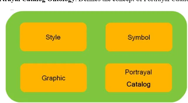
specifies the structure of and interrelationships between feature types, portrayal rules and symbols. It separates the content of the data from the portrayal of that data to allow the data to be portrayed in a manner independent of the dataset. The graphic description is intended to be format independent but convertible to any target formats (SVG, KML). The ontologies are derived from concepts found in existing portrayal specifications (ISO 19117, OGC Symbology Encoding and Styled Layer Descriptor Profile of WMS). We define microtheory as a ontology containing a small set of concepts, attributes and relationships that are consistent with a given theory. To favor reusability, the Portrayal ontologies are decomposed into four microtheories (see Figure 7).
Style ontology: defines the concept of Style and portrayal rules.
Symbol ontology: defines the concept of Symbol Set and Symbol and structural definition of Symbol components.
Graphic Ontology: defines graphic elements including graphic objects and attributes.
Portrayal Catalog Ontology: Defines the concept of Portrayal Catalog
Figure 7: Portrayal Microtheories
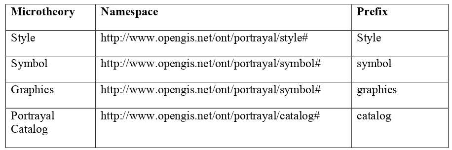
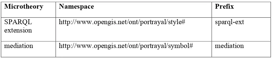
The details of each microtheory are described in the following sections. The namespace mapping for each microtheory is defined in Table 1 Namespace mapping for Portrayal Microtheories
Table 1 Namespace mapping for Portrayal Microtheories
Microtheory Namespace Prefix
Style http://www.opengis.net/ont/portrayal/style# Style Symbol http://www.opengis.net/ont/portrayal/symbol# symbol Graphics http://www.opengis.net/ont/portrayal/symbol# graphics Portrayal
Catalog
http://www.opengis.net/ont/portrayal/catalog# catalog
9.2 Design Approach
This section outlines some the key principles used to design the portrayal ontologies.
9.2.1 Minimal ontological commitment
Our modular design of the ontologies follows the principle of making a minimal
ontological commitment to the nature of concepts and of relationships between concepts. As explained by Thomas Gruber [4] an ontology should require the minimal ontological commitment sufficient to support the intended knowledge sharing activities. An ontology should make as few claims as possible about the world being modeled, allowing the parties committed to the ontology freedom to specialize and instantiate the ontology as needed (which is often called ontology profile).
Opting for such a minimal approach is made dramatically easier by the vocabulary extension mechanisms offered natively by Semantic Web technology. Applications that require more constrained behavior may define compatible extensions to OWL or SKOS. For example, modelers may coin sub-classes and sub-properties of OWL or SKOS properties, or associate those properties with specific formal axioms. By making a minimal ontological commitment, the ontologies can be applied and reused across multiple Communities of Interests (COIs), thus increasing the rate of wide-spread adoption.
9.2.2 Modularization of ontologies
design modules of a size that they can apprehend, and later either integrate these modules into a final repository or build the relationships among modules that support
interoperability. This is a typical application of the divide-and-conquer principle. Modularization also provides a way to keep performance of ontology services at an acceptable level. Performance concerns may be related to query processing techniques, reasoning engines and ontology modeling and visualization tools. Reasoners currently available are performing well on small-scale ontologies, with performance degrading rapidly as the size of the ontology increases. Keeping ontologies small is one way to avoid the performance loss, and modularization is a way to replace an ontology that tends to become oversized by smaller subsets. Modularization fulfills the performance goal if, whenever a query has to be evaluated or an inference to performed, this can be done by looking at just few modules, rather than exploring the whole ontology (Stuckenschmidt et al., 2009).
9.2.3 Reusability of ontologies
Reusability is a well-known goal in software engineering. Reuse is most naturally seen as an essential motivation for approaches aiming at building a broader, more generic
repository from existing, more specialized repositories. However, it may also apply to the inverse approaches aimed at splitting an ontology into smaller modules. In this case, the decomposition criterion should be based on the expected reusability of a module, i.e. how well can a module fill the purpose of various applications. Reusability emphasizes the need for rich mechanisms to describe a module in a way that maximizes the chances for modules to be understood, selected and used by other services and applications.
9.2.4 Understandability
An obvious prerequisite is the ability to use ontology to understand the concepts and properties it conveys. Whether the content is shown in visual or textual format, understanding is easier if the ontology is small (a module). Small ontologies are undoubtedly preferable if the user is a human being. However, size is not the only criterion that influences understandability. The way it is structured contributes to improving or decreasing understandability.
9.3 Style Ontology
Figure 8 Style Model Overview
9.3.1 Style
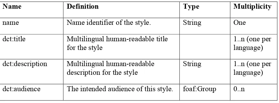
The Style concept is central to the Style ontology. Style associates symbol sets with portrayal rule sets, which define the mapping of feature types to symbols. Style also captures descriptive metadata and tradecraft information such as the audience for the style, scope of application and field of application. Table 2 summarizes the properties of the Style class.
Table 2: Style properties
Name Definition Type Multiplicity
name Name identifier of the style. String One
dct:title Multilingual human-readable title for the style
1..n (one per language) dct:description Multilingual human-readable
description for the style
scope Descriptive definition of the scope of application of the style
String 0..1
language Language associated with the style String 0..n style:symbolSet SymbolSet associated with the style SymbolSet 1..n fieldOfApplication The field of application of this style,
where values are defined as SKOS concept in a taxonomy.
The following example shows the definition of the EMS Style with audience information organized as an hierarchy.
@prefix : <http://www.opengis.net/testbed/11/cci/ems/style#> . @prefix rdfs: <http://www.w3.org/2000/01/rdf-schema#> . @prefix style: <http://www.opengis.net/ont/portrayal/style#> . @prefix foaf: <http://xmlns.com/foaf/0.1/> .
@prefix dct: <http://purl.org/dc/terms/> .
@prefix feature: <http://www.opengis.net/ont/feature#> . @prefix group: <http://www.socialml.org/ontologies/group#> .
@prefix ems: <http://www.opengis.net/testbed11/ont/incident/ems#> .
:EMSStyle a style:Style ; dct:audience
<http://ows.usersmarts.com/ldapp/audiences/community/CanadianEmergencyAndDisast erManagement> ;
dct:description "Style defining the set of rules for mapping incident types from EMS to symbology" ;
<http://ows.usersmarts.com/ldapp/audiences/community/CanadianEmergencyAndDisast
A portrayal rule set describes a function set which maps the feature types of a feature catalog to a symbol. A PortrayalRuleSet is composed of one or more portrayal rules, which in turn maps an individual feature type to a symbol. Table 3 provides a summary of the PortrayalRuleSet
Table 3 PortrayalRuleSet properties
Name Definition Type Multiplicity
dct:title Multilingual human readable name for the PortrayalRuleSet.
string 0..n (one per language) dct:description Multilingual human readable
description for the PortrayalRuleSet.
string 0..n (one per language) hasRule PortrayalRule member of this
PortrayalRuleSet.
PortrayalRule 0..n
The following is a sample of the PortrayalRuleSet defined for the EMS Style @prefix : <http://www.opengis.net/testbed/11/cci/ems/style#> .
@prefix style: <http://www.opengis.net/ont/portrayal/style#> . @prefix dct: <http://purl.org/dc/terms/> .
:EMSRuleSet a style:PortrayalRuleSet ;
dct:description "Set of rules for mapping incident types from EMS to symbology" ; dct:title "EMS Portrayal Rule Set" ;
style:hasRule :ems.incident.temperature.windChill-portrayal-rule ,
:ems.incident.roadway.hazardousRoadConditions-portrayal-rule , :ems.incident.civil-portrayal-rule ,
…
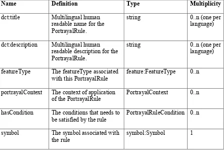
A PortrayalRule defines a rule that associates a feature type (feature:FeatureType) to a symbol (symbol:Symbol) satisfying a certain condition (PortrayalRuleCondition) in a given context (PortrayalContext). Table 4 summarizes its properties.
Table 4 PortrayalRule properties
Name Definition Type Multiplicity
dct:title Multilingual human
featureType The featureType associated with this PortrayalRule
feature:FeatureType 0..n
portrayalContext The context of application of the PortrayalRule
PortrayalContext 0..n
hasCondition The conditions that needs to be satisfied by the rule
PortrayalRuleCondition 0..n
symbol The symbol associated with the rule
symbol:Symbol 1
The listing below shows an example of PortrayalRule for Windchill. The PortrayalRule applied on the ems:EMSIncident featureType and associates the EMS symbol for
Windchill defined by the URL:
:ems.incident.temperature.windChill-portrayal-rule a style:PortrayalRule ;
dct:description "Portrayal rule for incident type ems.incident.temperature.windChill" ; dct:title "Wind Chill incident portrayal rule" ;
style:featureType ems:EMSIncident ;
style:hasRuleCondition :ems.incident.temperature.windChill-portrayal-rule-condition; style:symbol
<http://www.opengis.net/testbed/11/cci/ems/symbols#ems.incident.temperature.windChill -symbol> .
9.3.4 PortrayalRuleCondition
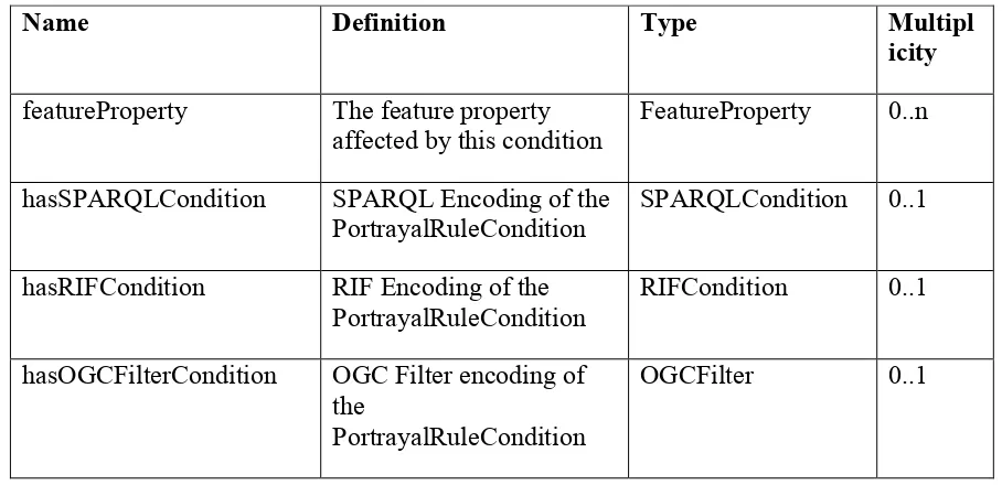
The PortrayalRuleCondition defines the condition in which a portrayal rule applies for a given feature. The PortrayalRuleCondition can be encoded using multiple encodings. Table 5 summarizes the properties of PortrayalRuleCondition
Table 5 PortrayalRuleCondition Properties
Name Definition Type Multipl
icity
featureProperty The feature property affected by this condition
FeatureProperty 0..n
hasSPARQLCondition SPARQL Encoding of the PortrayalRuleCondition
SPARQLCondition 0..1
hasRIFCondition RIF Encoding of the PortrayalRuleCondition
RIFCondition 0..1
hasOGCFilterCondition OGC Filter encoding of the
PortrayalRuleCondition
OGCFilter 0..1
The following example demonstrates the encoding of the portrayal rule condition for the Portrayal rule for the symbol Windchill. The condition applies on the feature property ems:incidentType. If the value of this property is equals to
http://www.opengis.net/taxonomy/ems#ems.incident.temperature.windChill then the rule
:ems.incident.temperature.windChill-portrayal-rule-condition a style:PortrayalRuleCondition ;
style:featureProperty ems:incidentType ;
style:hasOGCFilterCondition [ a style:OGCFilter ; style:body
"<ogc:Filter><ogc:PropertyIsEqualTo><ogc:PropertyName>incidentType</ogc:Prop ertyName><ogc:Literal>http://www.opengis.net/taxonomy/ems#ems.incident.temperatur e.windChill</ogc:Literal></ogc:PropertyIsEqualTo></ogc:Filter>"
] ;
style:hasRIFCondition [ a style:RIFCondition ; style:body "Prefix(ems
<http://www.opengis.net/testbed11/ont/incident/ems#>)\nExists ?this ( ems:incidentType(?this
<http://www.opengis.net/taxonomy/ems#ems.incident.temperature.windChill>) )" ] ;
style:hasSPARQLCondition [ a style:SPARQLCondition ; style:body "PREFIX ems:
<http://www.opengis.net/testbed11/ont/incident/ems#>\nASK \nWHERE { ?this ems:incidentType
<http://www.opengis.net/taxonomy/ems#ems.incident.temperature.windChill>.\n}" ]
] ;
The rule is expressed in three different encodings: OGC Filter, SPARQL and RIF. The SPARQL query is formulated as a ASK query which returns a boolean value. The variable ?this is bound to the current instance of featureType that is being tested. PREFIX ems: <http://www.opengis.net/testbed11/ont/incident/ems#>
ASK WHERE {
?this ems:incidentType
<http://www.opengis.net/taxonomy/ems#ems.incident.temperature.windChill>. }
The equivalent RIF condition is expressed as:
Prefix(ems <http://www.opengis.net/testbed11/ont/incident/ems#>) Exists ?this
( ems:incidentType(?this
The SPARQLCondition and RIFCondition can be used by a semantic portrayal rule engine that consumes feature data represented as Linked Data (recommendation for next testbed). We foresee that the portrayal catalog containing these rules can be extended with a rendering service that will apply the rules on a set of linked data compatible with the style and generates the portrayal rendering to a number of target formats (SVG, KML etc..). We suggest we experiment this capability in the next Testbed.
The PortrayalRuleCondition was used by a Web Processing Service (WPS) to generate the SLD document for a given Style, by using the OGCFilter associated with the Rule. To perform the bridge between the Linked Data representation of the FeatureType and GML representation we annotated the FeatureType and FeatureProperty with the attribute gmlName to indicate what is the mapping between the conceptual definition and the GML syntactic definition based on XML schema.
The following example shows the feature type definition for EMSIncident with the gmlName annotations.
ems:EMSIncident a feature:FeatureType ;
rdfs:comment "Incident defined for Canadian Emergency Management System" ; rdfs:label "EMSIncident" ;
feature:gmlName "ems:EMSIncident" .
ems:incidentType a feature:FeatureProperty ; rdfs:label "incidentType" ;
feature:gmlName "ems:incidentType" .
The following example shows the feature type definition for HSWGIncident with the gmlName annotations.
hswg:HSWGIncident a feature:FeatureType ;
rdfs:comment "Incident defined for Homeland Security Working Group" ; rdfs:label "HSWGIncident" ;
feature:gmlName "hswg:HSWGIncident" .
hswg:incidentType a feature:FeatureProperty ; rdfs:label "incidentType" ;
feature:gmlName "hswg:incidentType" .
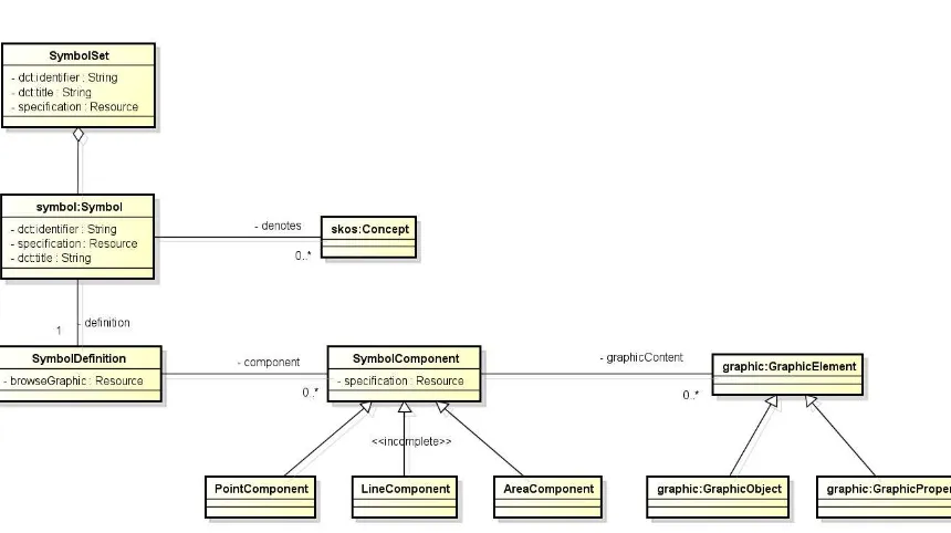
9.4 Symbology Ontology
Figure 9 Symbology Model Overview
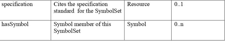
9.4.1 SymbolSet
SymbolSet collects symbols into sets of symbols that are used together. Symbols can be shared among symbol sets. A Symbol set can be equated with legend of a map.Table 6 summarizes the SymbolSet properties.
Table 6 SymbolSet Properties
Name Definition Type Multiplicity
dct:identifier Unique identifier for the symbol set mainly used by machine.
string One
dct:title Multilingual human readable name for the PortrayalRule.
string 0..n (one per language)
dct:description Multilingual human
readable description for the PortrayalRule.
specification Cites the specification standard for the SymbolSet
Resource 0..1
hasSymbol Symbol member of this SymbolSet
Symbol 0..n
The following example shows a sample of the EMS SymbolSet. @prefix : <http://www.opengis.net/testbed/11/cci/ems/symbols#> . @prefix rdfs: <http://www.w3.org/2000/01/rdf-schema#> .
@prefix graphic: <http://www.opengis.net/ont/portrayal/graphic#> . @prefix symbol: <http://www.opengis.net/ont/portrayal/symbol#> . @prefix dct: <http://purl.org/dc/terms/> .
@prefix skos: <http://www.w3.org/2004/02/skos/core#> .
:EMSSymbolSet a symbol:SymbolSet ;
dct:description "Standard Canadian Emergency Mapping Symbology (EMS) SymbolSet version 1.0" ;
dct:title "Canadian Emergency Mapping Symbology (EMS) SymbolSet (version 1.0)" ;
symbol:hasSymbol :ems.incident.roadway.roadwayClosure-symbol , :ems.incident.temperature.windChill-symbol , :ems.incident.temperature.heatWave-symbol , :ems.incident.civil.looting-:ems.incident.temperature.heatWave-symbol , :ems.incident.civil.dignitaryVisit-:ems.incident.temperature.heatWave-symbol , :ems.incident.civil.displacedPopulations-symbol , :ems.incident.publicService-symbol ; symbol:specification
<https://cms.masas-x.ca.s3.amazonaws.com/EMS_Symbology_v1.0.pdf> .
9.4.2 Symbol
A Symbol is the type used to define symbol classes. Symbols are collected into symbol sets. A symbol has one machine readable identifier. A Symbol is described by a title, description and can refer to a formal specification document. A symbol can denote a concept defined in a SKOS taxonomy. Table 7 summarizes the Symbol properties.
Table 7 Symbol Properties
Name Definition Type Multiplicity
dct:identifier Machine readable name for the symbol. The identifier should be unique
string 1
title for the symbol language) dct:description Multilingual human readable
description for the symbol
string 0..n (one per
language) specification Reference to the full details of
the portrayal symbol
Resource 0..1
denotes Concept that is denoted by the symbol
skos:Concept 0..n
definition Symbol Definition defining the composition structure of the symbol
SymbolDefinition 0..1
symbolSet The SymbolSet which this symbol belongs to.
SymbolSet 0..n
skos:notation Notation used to refer the symbol as defined in a notation system. Use a custom datatype if multiple notations are used
string 0..n
The following listing shows the encoding in Turtle for the WindChill symbol belonging to the EMS SymbolSet.
:ems.incident.temperature.windChill-symbol a symbol:Symbol ;
rdfs:label "windChill" ;
dct:identifier "ems.incident.temperature.windChill" ;
symbol:definition :ems.incident.temperature.windChill-symbolDefinition ; symbol:denotes
<http://www.opengis.net/taxonomy/ems#ems.incident.temperature.windChill> ; symbol:specification
<https://cms.masas-x.ca.s3.amazonaws.com/EMS_Symbology_v1.0.pdf> ; symbol:symbolSet :EMSSymbolSet ;
skos:notation "ems.incident.temperature.windChill"^^:emsNotation .
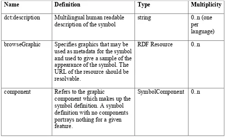
9.4.3 SymbolDefinition
to define a symbol. This concept has been aligned with the ISO 19117 standard. Table 8 summarizes the properties of the SymbolDefinition.
Table 8 SymbolDefinition Properties
Name Definition Type Multiplicity
dct:description Multilingual human readable description of the symbol
string 0..n (one
per language) browseGraphic Specifies graphics that may be
used as metadata for the symbol and used to give a sample of the appearance of the symbol. The URL of the resource should be resolvable.
RDF Resource 0..n
component Refers to the graphic
component which makes up the symbol definition. A symbol definition with no components portrays nothing for a given feature.
SymbolComponent 0..n
The following sample encoded in Turtle format shows the symbol definition of the windChill symbol, which is composed of a pointIcon .
:ems.incident.temperature.windChill-symbolDefinition a symbol:PointSymbolDefinition ;
dct:description "Technical definition for symbol ems.incident.temperature.windChill"; symbol:browseGraphic
<http://ows.usersmarts.com/ems/icons/tier1/Base/ems.incident.temperature.windChill.pn g> ;
symbol:component :ems.incident.temperature.windChill-pointIcon .
9.4.4 SymbolComponent
Table 9 SymbolComponent properties
Name Definition Type Multiplicity
specification Cites the specification standard for the graphics definition language used to define the symbol
component.
string 0..1
graphicContent Specified the graphic
elements which make up the symbol component
graphic:GraphicElement 0..n
In this Testbed, we only focused on the implementation of icon-based symbol
component. We defined a subclass of SymbolComponent called PointIcon to represent icon-based symbol component. It has a property graphic content referring to an icon image.
The following example defines the Point Icon for WindChill symbol in EMS. :ems.incident.temperature.windChill-pointIcon
a symbol:PointIcon ; symbol:graphicContent
<http://ows.usersmarts.com/ems/icons/tier1/Base/ems.incident.temperature.windChill.pn g> ;
symbol:specification <https://cms.masas-x.ca.s3.amazonaws.com/EMS_Symbology_v1.0.pdf> .
9.5 Graphics Ontology
The Graphics Ontology defines a vocabulary to describe graphic elements at the semantic level. Due to the limited time for this Testbed, the Graphics ontology focused mainly on defining two concepts: ExternalGraphic (for EMS raster icons) and Font (for HSWG fonts). The graphics Ontology needs to be extended in future Testbed to represent graphic objects and attributes for 0D, 1D and 2D such as line thickness, color, etc… As we develop these future extensions, we may consider breaking down the graphic ontology into several microtheories in order to favor reusability and scalability.
9.5.1 External Graphic
and a property format to indicate the mime type of the resource. Multiple format of the same resource can be fetched, thus we allow the cardinality of this property to be 1 to n. Table 10 summarizes the property of ExternalGraphic concept.
Table 10 ExternalGraphic properties
Name Definition Type Multiplicity
format The format of the external graphic expressed as MIME type
string 1..n
onlineResource The url to access the resource. The URL should be resolvable.
Resource 1
The following example shows how the RoadWayClosure symbol graphic is represented using ExternalGraphic.
<http://ows.usersmarts.com/ems/icons/tier1/Base/ems.incident.roadway.roadwayClosure .png>
a graphic:ExternalGraphic ;
rdfs:label "ems.incident.roadway.roadwayClosure icon" ; dct:description "icon for ems.incident.roadway.roadwayClosure" ; graphic:format "image/png" ;
graphic:onlineResource
<http://ows.usersmarts.com/ems/icons/tier1/Base/ems.incident.roadway.roadwayClosure .png> .
9.5.2 Font, FontFamily and Foundry
For this testbed, we refactor the Font, FontFamily and Foundry ontology from the Testbed 10 into the graphic ontology. The Font and FontFamilty properties are summarized in Table 11and Table 12.
Table 11 Font properties
Name Definition Type Multiplicity
fontCode The code of the font within the font family.
string 1
Table 12 FontFamily Properties
Name Definition Type Multiplicity
familyName The family name string 1
foundry The font foundry that created the font family.
Foundry 0..1
The following example shows the SymbolDefinition for the HSWG shooting symbol associated with a Font defined in True type family.
:ShootingSymbolDefinition
a symbol:PointSymbolDefinition ;
dct:description "Technical definition for symbol ShootingSymbol" ; symbol:component :ShootingSymbol-pointText .
:ShootingSymbol-pointText
a symbol:PointText ;
symbol:graphicContent <tty:ERS_v2_Incidents#0x4B> ;
symbol:specification <http://www.fgdc.gov/HSWG/ref_pages/Incidents_ref.htm> .
<tty:ERS_v2_Incidents#0x4B> a graphic:Font ;
rdfs:label "ShootingSymbol font" ; graphic:fontCode "0x4B" ;
graphic:fontFamily <tty:ERS_v2_Incidents> .
<tty:ERS_v2_Incidents>
a graphic:FontFamily ; graphic:familyName "ERS v2 Incidents" ; graphic:foundry <http://symbolstore.org> .
<http://symbolstore.org> a graphic:Foundry ; rdfs:label "symbolstore.org" .
9.6 Portrayal Catalog Ontology
Styles, Portrayal Rules, Symbol Sets with Symbols and Symbol definitions. The aim of this ontology is to provide support for discovery of styles, symbols and symbol sets for supporting portrayal. The fact that this information is encoded semantically enables the support of reasoning and extensions such as tradecraft information (audience, purpose, functions, qualities information). Due to the lack of time, this ontology was not fully formalized. This will need to be addressed in a future Testbed.
10 Portrayal Encoding
10.1 HSWG Portrayal Encoding
The HSWG Portrayal encoding was derived programmatically from the SKOS encoding of the taxonomy of HSWG Emergency Symbology (which was captured manually the testbed 10), as the symbols and incident types are matching one to one. The final results were split into three files:
The SKOS encoding of the HSWG Incident taxonomy;
The Portrayal rules for HSWG which defines the HSWG Style and Portrayal Rules; and
The HSWG Symbol Set which defines the HSWG Symbol Set, associated symbols, Symbol definitions, components and graphics.
These three files were uploaded on the server in a RDF store and exposed through a SPARQL endpoint and Portrayal catalog REST API.
10.2 EMS Portrayal Encoding
The Canadian EMS Portrayal encoding was derived programmatically from the SKOS encoding of the taxonomy of EMS (which was captured manually for this testbed), as the symbols and incident types are matching one to one. The final results were split into three files:
The SKOS encoding of the Canadian EMS Incident taxonomy;
The Portrayal rules for EMS which defines the EMS Style and Portrayal Rules; and
The EMS Symbol Set which defines the EMS Symbol Set, associated symbols, Symbol definitions, components and graphics.