RADIOMETRIC CALIBRATION OF DUAL SENSOR CAMERA SYSTEM,
A COMPARISON OF CLASSICAL AND LOW COST CALIBRATION
Martin Misgaiski-Hass, Jan Hieronymus
Humboldt-Universität zu Berlin Department of Computer Science
Computer Vision
Unter den Linden 6, 10099 Berlin, Germany [email protected]
http://www2.informatik.hu-berlin.de/cv
Commission V,WG V/1
KEY WORDS:Radiometry, Radiometric Camera Calibration, Comparison, Industry, Cost
ABSTRACT:
Several identical dual camera systems with two different spectral sensitivities have to be calibrated radiometrically and geometrically. The aim of this project is to build up a calibration laboratory for the calibration of a set of identical cameras using low cost equipment and to compare the results to classical/professional equipment. The main goal of this paper is to demonstrate how to use a low cost, inhomogeneous LED-backlight to measure the Pixel Response Non-Uniformity (PRNU) of the investigated cameras.
1. INTRODUCTION
A professional calibration laboratory is very expensive, so small companies shy away from spending much money to improve the quality of their camera systems by means of calibration. The question is, do these companies really need an expensive, top quality calibration laboratory to improve their products? The aim of this project is to build up a calibration laboratory for the cal-ibration of a set of identical cameras using low cost equipment and to compare the results to classical/professional equipment.
The company, for which the laboratory has been set up, prefers not to be mentioned. Likewise, no exact information about the used sensors and filters will be published. Three different tasks were specified/investigated:
• Radiometric characterization of the sensor (actually whole camera): linearity, DSNU and PRNU
• Adjusting the focus to infinity
• Geometric characterization (Determining the distortion pa-rameters by Brown)
Besides the already mentioned aims, it is one additional objec-tive, to automate the measurement procedures and calculations as much as possible. This paper will focus on the radiometric characterization of the sensor and briefly on the adjustment of the focus. A LED backlight panel is compared to a professional integrating sphere.
2. CAMERA AND LED BACKLIGHT
The investigated dual camera system consists of two individual monochrome cameras (later referred to as sensor 1 and sensor 2). The sensors are identical but equipped with to different filters and different optics. This leads to different spectral sensitivities and apertures. The spectral bandwidth of the sensor 1 is completely covered by the spectrum emitted by a white LED. The spectral
sensitivity of sensor 2 is mainly outside the spectrum of the LED. The LED provides a good amount of light for sensor 1 and just enough light for sensor 2. Both sensors are perfectly covered by the spectrum of a halogen tungsten light source used in the inte-grating sphere. Due to the large aperture of sensor 2, it is more sensitive compared to sensor 1 with respect to the spectrum of a halogen tungsten light source. This fact makes it necessary to adjust the brightness of the lamps in the integrating sphere for the use with the different sensors. This cannot be automated and leads to an increased manual effort. The LED, in contrast, can be used with both sensors without any adjustment. Measuring a flat field of sensor 2 with the LED will cover only a part of the spectral range. So it must be assumed, that the Photo Response Non-Uniformity (PRNU) per pixel does not vary much over the spectral range. In the following, only the results for sensor 1 are shown. All listed calculations were carried out for both, sensor 1 and sensor 2. The results for sensor 2 differ only slightly from sensor 1. For the determination of linearity, full well and PRNU we decided for a LED backlight of the company metaphase. It provides a shadow-free, flicker-free, diffuse light without much heat at a uniform light distribution of±5% (as specified by the manufacturer). In addition, a docking plate was created for the dual camera system to fit on the LED backlight. This prevents slippage or rotation of the camera. Thus the dual camera system images always the same part of the LED backlight, which is out of the focus of both cameras. The latter fact improves the homo-geneity. For the measurement of flat field images from the LED, the camera is put directly onto the safety glass of the LED back-light at a predetermined position. In figure 1 the complete LED backlight without docking plate is shown.
3. COLLIMATOR
The dual camera system should be manually set to infinity. In this case, both sensors should look into the beam path of the col-limator at the same time. Therefore, the aperture of the colli-mator has to be relatively large (about 15 cm). A professional collimator with a comparable aperture costs several thousand Eu-ros. The presented low cost solution consists of an inexpensive
The International Archives of the Photogrammetry, Remote Sensing and Spatial Information Sciences, Volume XL-5, 2014 ISPRS Technical Commission V Symposium, 23 – 25 June 2014, Riva del Garda, Italy
This contribution has been peer-reviewed.
Figure 1: Photo of the complete LED backlight. For better visu-alization the contrast is exaggerated.
astronomical Newtonian Telescope with the corresponding aper-ture, which has been converted into a collimator. The eyepiece is replaced by target with specialized LED-illumination unit. The whole module was produced with the help of a 3D-printer. The target is a professional commercial reticle. The obtained collima-tor was aligned and adjusted using a professional collimacollima-tor and fixed when properly set to infinity. The costs of this collimator are about 400 Euros. However, it has to be noted, that there is no possibility to defocus the collimator well-defined and that the target is not replaceable.
4. CALIBRATION
4.1 Geometric calibration
To determine the distortion parameters by Brown, a classical pho-togrammetric approach with circular targets was applied. For this purpose, a laboratory wall was provided with about 500 adhesive points, set in a completely irregular arrangement. Coded targets were not used. The algorithms for labelling the targets will be published in (Hieronymus, 2014).
4.2 Dark Signal Non-Uniformity (DSNU)
For the determination of DSNU (formula (1)) 100 dark images at 30 different integration times have been recorded. For each pixel the offset (Offset) and the integration-time dependent term (DC(intT)) was determined. The temperature-dependent part (DC(t)) is not used, but shown for completeness. Figure 2 shows the determination of Offset and DC(intT) for a pixel. The Offset, which does not depend on the temperature, can be considered as fixed in time (Mansouri et al., 2005).
DSNU=Offset+DC(intT)+DC(t) (1)
4.3 Pixel Response Non-Uniformity (PRNU)
The usual and straightforward way for flat-field correction is ob-taining corrective coefficients for each pixel from flat-field im-ages and applying these coefficients to each image after remov-ing the dark image model first (Friedrich et al., 2006). For the in-vestigation an integrating sphere was used additionally. Figure 3 shows a flat field image (FFI) averaged over 100 single shots of the integrating sphere. For comparison figure 4 shows a flat field image averaged over 100 shots of the LED backlight.
The maximum intensity in the image of the integrating sphere is in the center of the image, as expected. The maximum intensity
0 5 10 15 20 25 30
Figure 2: Dark Signal of one representative Pixel. 100 images for each integration time were used.
0
0 200 400 600 800 1000 1200
5600
Figure 3: Flat field image (FFI) of the integration sphere, aver-aged over 100 images.
0
0 200 400 600 800 1000 1200
5200
Figure 4: Flat field image (FFI) of the LED backlight, averaged over 100 images.
in the image of the LED is eccentric. To use the LED backlight as a source for flat field images instead of an integrating sphere, the inhomogeneity of the LED backlight must be corrected.
For the correction of the Pixel Response Non-Uniformity (PRNU), a flat field correction matrix (FFC) was calculated ac-cording to formula (2).
FFC= FFI−(Offset+DC(intT)) mean(FFI−(Offset+DC(intT)))
(2)
The inhomogeneity of the LED backlight must be accurately
de-The International Archives of the Photogrammetry, Remote Sensing and Spatial Information Sciences, Volume XL-5, 2014 ISPRS Technical Commission V Symposium, 23 – 25 June 2014, Riva del Garda, Italy
This contribution has been peer-reviewed.
termined. For this purpose exposure series of the integrating sphere and the LED backlight were recorded with two identi-cal cameras. The correction matrix (figure 5) for the camera was determined on the basis of images of the integrating sphere (FFC_UK). The images of the LED backlight were corrected us-ing the correction matrix (FFC_UK). This operation defines the inhomogeneity of the LED (LED_NU) (figure 6). It turned out that the cloudy areas as shown in figure 1, in the flat field cor-rected camera image (figure 6) were not recognizable. The inho-mogeneity is rather a grayramp (figure 7). This ramp is caused by a minimal oblique installation of the LED with respect to the safety glass.
0 200 400 600 800 1000 1200
0. 9
Figure 5: Flat field correction matrix (FFC) calculated from the integrating sphere.
0 200 400 600 800 1000 1200
0. 96
Figure 6: Inhomogeneity of the LED backlight, with profile line.
C
4.362e-08X2m+m2.0977e-05Xm+m0.96175
Polynomem2ndmorder
Correctionmfactors alongmthemprofilemline
Figure 7: Profile through LED_NU, shown in figure 6.
5. VALIDATION
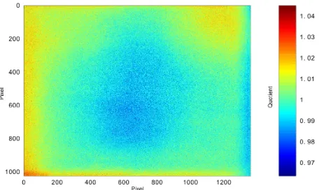
For validation, two dual camera systems were used. Using cam-era 1 the LED_NU was determined. For camcam-era 2 its FFC_UK was determined using the integrating sphere. The recordings of the LED backlight were DSNU and LED_NU corrected. The resulting image can be used to calculate the flat field correction matrix FFC_LED (figure 8) determined by formula 3.
FFC_LED=
Figure 9 shows the division FFC_UK by FFC_LED. As can be seen, there is only a very small deviation of about±3%. For many applications this can be considered precise enough.
0
0 200 400 600 800 1000 1200
0. 9
Figure 8: Flat field correction matrix (FFC) calculated from the LED backlight.
Figure 9: Flat field correction matrix (FFC) calculated from the integrating sphere divided by Flat field correction matrix (FFC_LED) calculated from the LED backlight.
6. CONCLUSION
Under the assumption of identical cameras the use of inhomoge-neous LED back lights is possible. With a relatively small finan-cial effort the imaging quality can be improved significantly. Due to production tolerances each camera will have a slightly differ-ent imaging system. Even if the camera is placed exactly at the same position as the calibrated reference camera, it will image a slightly different part of the LED light source. This will produce small residuals in the flat field correction matrix for that cam-era. This test shows that these differences are relatively small
The International Archives of the Photogrammetry, Remote Sensing and Spatial Information Sciences, Volume XL-5, 2014 ISPRS Technical Commission V Symposium, 23 – 25 June 2014, Riva del Garda, Italy
This contribution has been peer-reviewed.
and may be neglected if the requirements towards the radiome-try are not too strict. However, it is absolutely necessary to keep at least one identical professionally calibrated camera in stock. Such a so called "golden sample" is used to track changes in the calibration equipment. Only under this condition it is possible to determine the inhomogeneity of the LED backlight. A change of the inhomogeneity due to aging is possible. Therefore a re-peated determination of LED_NU is recommended. Additionally the typical spectral characteristics of LED have to be considered.
REFERENCES
Friedrich, J., Lelo˘glu, U. M. and Tunali, E., 2006. Radiomet-ric camera calibration of the bilsat small satellite: Preliminary results. ISPRS Topographic Mapping from Space (with Special Emphasis on Small Satellites), Ankara, Turkey, CD- ROM. 1(2), pp. 3–4.
Hieronymus, J., 2014. Automatic label completion for test field calibration. ISPRS Annals of the Photogrammetry, Remote Sens-ing and Spatial Information Sciences, Volume II-5, 2014 ISPRS Technical Commission V Symposium, 23 – 25 June 2014, Riva del Garda, Italy.
Mansouri, A., Marzani, F. and Gouton, P., 2005. Development of a protocol for ccd calibration: application to a multispectral imaging system. International Journal of Robotics and Automa-tion 20(2), pp. 94–100.
The International Archives of the Photogrammetry, Remote Sensing and Spatial Information Sciences, Volume XL-5, 2014 ISPRS Technical Commission V Symposium, 23 – 25 June 2014, Riva del Garda, Italy
This contribution has been peer-reviewed.