PARAMETRIC STUDY OF FLEXURAL
STRENGTHENING OF RC BEAM USING EXTERNAL
REINFORCEME
.
T
AZMI BIN AMAT
Universiti Malaysia Sarawak
1999TA
405 A995 1999
Pu at Khidmat Maklumat A adem,,, U IVER IT! MALAY 1. SARAWAK
PARAMETRIC STUDY OF FLEXURAL STRENGTHENING OF RC BEAM
USING EXTERNAL REINFORCEMENT
AZMI BIN AMAT
-
- - - - *
A Project Report Submitted in Partial Fulfillment for the Bachelor of Degree of Engineering (Civil) with Honours in the Faculty of
Engineering Universiti Malaysia Sarawak 1999
BORANG PENYERAHAN TESIS
ludul: I)ARAMETRIC STUDY OF FLEXURAL STRENGTHENING OF RC BEAM USING EXTERNAL REINFORCEMENT
SESI PENGAJIAN 1998/99
Saya: AZMI BIN AMAT
mengaku membenarkan tesis ini disimpan di Pusat Khidmat Maklumat Akademik, Universiti Malaysia Sarawak dengan syarat-syarat kegunaan seperti berikut:
I. Hakmilik kertas projek ini adalah dibawah nama penulis melainkan penulisan sebagai projek bersama dan dibiayai oleh UNIMAS, hakmiliknya adalah kepunyaan UNIMAS.
2. Naskhah salinan didalam bentuk kertas atau mikro hanya boleh dibuat dengan kebenaran bertulis daripada penulis.
3. Pusat khidmat maklumat Akademik, UNIMAS dibenarkan membuat salinan untuk pengajian mereka.
4. Kertas projek hanya boleh diterbitkan dengan kebenaran penulis. Bayaran royalti adalah mengikut kadar yang dipersetujui kelak.
5. * Saya membenarkanltidak membenarkan Perpustakaan membuat kertas salinan projek ini sebagai bahan pertukaran diantara institusi pengajian tinggi.
6. ** Sila tandakan (.f)
o
SULIT (Mengandungi maklumat yang berdarjah keselamatan atau kepentingan Malaysia seperti yang termaktub didalam AKT A RAHSIA RASMI 1972).o
TERHAD (Mengandungi maklumat TERHAD yang telah ditentukan oleh organisasi/badan dimana penyelidikan dijalankan)o
TIDAK TERHADDisahkan oleh
(TANDATANGAN PENULlS)
~ENYELlA)
Alamat tetap:
Kpg. Nauran, Jln. Pandaruan Dr. Ng. Chee Khoon
98700 Limbang Fakulti Kejuruteraan,
Sarawak. UNlMAS.
Tarikh:
_-=--::;-+-/_~--L..l_(-=-"_"-,-7
__
Tarikh:---I-7-+-1_!;+-1
q-'~=----_
~
CATATAN * Potong yang tidak berkenaan
** Jika Kertas Projek ini SULIT atau TERHAD, sila lampirkan surat daripada pihak berkuasalorganisasi berkenaan dengan menyertakan sekali tempoh kertas projek.
APPROVAL SHEET
This project report attached here to, entitled "Parametric Study of Flexural Strengthening of RC Beam Using External Reinforcement," prepared and submitted by Azmi bin Amat in partial fulfillment of the requirement for the degree of Bachelor of Engineering (CIVIL) is hereby accepted.
Date:
7
/>
-
/
e;;
0]
(Dr. Ng Chee Rhoon)Lecturer
Civil Engineering Department Faculty of Engineering
University Malaysia Sarawak
Date: (Azmi bin Amat)
Kampung Nauran, JIn Pandaruan, 98700 Limbang, Sarawak
Dedicated to my
Papa
&Mama, Brothers
&sisters, Nephews
&nieces,
friends
&loves one.
ACKNOWLEDGEMENTS
My most sincerely thanks to people who have contributed towards the preparation of this project. Firstly, thank to Dr. Ng Chee Khoon., project supervisor, for his guidance, invaluable advises, comments and encouragement's throughout this project. Thanks also to all lectures and staffs of the Engineering Faculty, UNIMAS, for their strong supports.
Not forgetting my family, especially to my father Hj. Amat bin Gerai and my mother Hjh, Esah bte. Hj. Misil, thanks for all the helps and motivation alone the way to completing this project. Acknowledgement will not be complete without mentioning a]] my friends especially to my ex-housemates at Tanjung Bundong and all my classmates, who have given their constant encouragement and steadfast support. To all those named above and any others, who may have been omitted, I am extremely thankful.
ABSTRACT
This study presents a parametric study of flexural strengthening of reinforced concrete
beam using external steel reinforcement. The intent of this study is to evaluate the increase in flexural strength of reinforced concrete beams using external steel reinforcement due to the parameters of the existing reinforced concrete beam and
external steel reinforcement. An analytical model was proposed for the analysis of
rei nforced concrete beams with external steel reinforcement. This analytical model was used in the parametric study. In this study, the beams were analysed with three different characteristic concrete strengths, values of internal steel reinforcement ratio and effective depth and amount of external steel reinforcement. A Fortran programme was written to determine the neutral axis depth of the beams based on equilibrium.
The neutral axis depth is determined in order to calculate the ultimate strength and failure mode of the beam. Charts of strengthening ratio versus relative reinforcing index were constructed. The lines of balance failure limit were also presented to indicate the limit of the amount and effective depth of external steel reinforcement corresponding to the balanced failure mode of the internal steel reinforcement. The charts provide the guidelines in
."
the design of flexural strengthening of reinforced concrete beams using external steel reinforcement.ABSTRAK
Kajian parameter ini dijalankan adalah untuk mengkaji kekuatan lenturan bagi rasuk
konkrit bertetulang yang menggunakan tetulang keluli luaran. Kandungan kajian ini adalah untuk mencari peningkatan kekuatan lenturan hagi rasuk konkrit bertetulang
yang menggunakan tetulang keluli luaran yang berdasarkan kepada kajian terhadap faktor-faktor parameter bagi rasuk konkrit itu sendiri dan juga tetulang keluli luaran.
Satu model kajian bagi rasuk konkrit bertetulang yang menggunakan tetulang keluli
luaran telah dibentuk babrl rnenjalankan analisis terhadap parameter yang telah di pilih. Dalam kajian ini rasuk dianalisis dengan menggunakan tiga jenis kekuatan ciri bah an konkrit, nilai bagi nisbah bar tetulang dalarnan dan juga kedalaman berkesan
dan jumlah tetulang keluli luaran. Pengaturcaraan komputer menggunakan Fortran telah di buat babrl rnendapatkan nilai bagi kedalarnan paksi nuetral rasuk untuk setiap kes. Kedalaman paksi neutral ini adalah untuk mengira momen muktamad dan juga
titik kegagalan bagi rasuk.. Graf bagi nisbah kekuatan rasuk. melawan index tetu]ang diplot bersertakan dengan garisan had kegagalan rasuk. Garisan ini menWljukkan had bagi jumlah dan kedalaman berkesan tetulang keluli luaran rasuk berdasarkan kepada
.'
kegagalan kepada bar keluli bagi tetulang dalarnan. Graf ini menyediakan carakeIja bagi merekabentuk kekuatan lenturan bagi rasuk konkrit bertetulang yang menggunakan tetulang luaran.
Pusat Khidmat Maklumat Akaderni
UNlVERSITI MALAYSJA SARAWAK
T ABLE OF CONTENTS
CONTENTS
Page
BORANG PENYERAHAN THESIS ii
APPROV AL SHEET III
DEDICATION iv
ACKNOWLEDGEMENT v
ABSTRACT vi
ABSTRAK vii
TABLE OF CONTENT viii
LIST OF APPENDICES x
LIST OF FIGURES xii
NOTATIONS xiii
CHAPTER 1 INTRODUCTION 1
1.1 General
1.2 Objective 2
CHAPTER 2 LITERATURE REVIEW 3
2.1 Introducti~, 3
2.2 Applications in Structural Strengthening 4
2.2.1 External Steel Plate 4
2.2.2 External Presstressing 6
2.2.3 External FRP plates 7
2.3 Failure Modes and Flexural Strength of
Reinforced Concrete Beams. 8
2.4 Balanced Failure ofa Beam with a
Rectangular Cross-Section. 10
CHAPTER 3 ANALYTICAL CONSIDERATIONS 13
3.1 Introduction 13
3.2 Ultimate Flexural Strength 13
3.3 Strengthening Ratio (SR) 18
CHAPTER 4 RESULTS AND DISCUSSIONS 20
4.1 Materials and Geometries 20
4.2 Relative Reinforcing Index 23
4.3 Effects of Various Parameters in Beam
Strengthening Using External Reinforcement 33
4.3.1 Effect of Concrete Strength . 33
4.3.2 Effects of Internal Steel reinforcement 34
4.3.3 Combined Effect of Concrete Strength and
Steel Reinforcement. 35
4.3.4 Effect of External Steel Reinforcement 35
4.4 Design of Strengthening ofRC Beam Using
External Steel Reinforcement 37
CHAPTER 5 CONCLUSIONS AND RECOMMENDATIONS 42
REFERENCE 44
APPENDICES
II APPENDIX A APPENDIX B APPENDIX C APPENDIX D APPENDIX E APPENDIX F APPENDIX G APPENDIX H APPENDIX I APPENDIX J APPENDIX K !
LIST OF APPENDICES
Fortan program for determining the values of depth of neutral axis for stren!:,riliened beam, x, and calculates the ultimate moment for strengthend beam, Mu
Fortran Program for detennining the values of depth of neutral axis for unstrengthened beam, X un. and calculates the ultimate moment
for unstrengthened beam, MUll.
Table of calculations of strengthening ratio and reinforcing index for feu = 20 MPa and Aslhd; = 0.50%.
Table of calculations of strengthe.ning ratio and reinforcing index for!cu = 20 MPa and As/ hd; = 1.0%.
Table of calculations of strengthening ratio and reinforcing index
forfcu = 20 MPa and Asl bd; = 1.50%.
Table of calculations of strengthening ratio and reinforcing index for feu = 25 MPa and Asl bd; = 0.50%.
Table of calculations of strengthening ratio and reinforcing index
forfcu = 25 MPa and Aslbd; = 1.0%.
Table of calculations of strengthening ratio and reinforcing index for fCiI = 25 MPa and Asl bd; = 1.50%.
Table of calculations of strengthening ratio and reinforcing index for fcu = 30 MPa and Asl bd; = 0.50%.
Table of calculations of strengthening ratio and reinforcing index for feu = 30 MPa and As/ bdi = 1.0%.
Table of calculat1Mts of strengthening ratio and reinforcing index for feu = 20 MPa and Asl bd; = 1.50%.
I
LIST OF FIGURES
,..
Fig. 1.1 Flexural and shear strengthening of reinforced concrete beams. Fig. 2.1 Stress-strain diagram of structural steel.
Fig. 2.2 Stress-strain diagram of structural steel for plastic design.
Fig. 2.3 The variations of bending stress with moment in an undereinforced beam loaded progressively to failure.
Fig. 2.4 lntluence of steel area on the magnitude of the strain in the top concrete fiber at the initial yielding of steel.
Fig. 3.1 Strain and stress distributions at failure.
Fig. 4.1 Strain and stress distribution at failure in different cases.
Fig. 4.2 Charts of strengthening ratio versus relative reinforcing index (ic.1,=20MPa, Aslbd; = 0.50%)
Fig. 4.3 Charts of strengthening ratio versus relative reinforcing index (fcu=20 MPa, A.•l bd; = ].0%)
Fig. 4.4 Charts of strengthening ratio versus relative reinforcing index ifcu=20 MPa, Asl bd; = 1.50%)
Fig. 4.5 Charts of strengthening ratio versus relative reinforcing index (ic.u=25 MPa, Asl bd; = 0.50%)
Fig. 4.6 Charts of strengthening ratio versus relative reinforcing index (j.1,=25 MPa, Asl bd; =: ] .0%)
Fig. 4.7 Charts of strengthdlling ratio versus relative reinforcing index (ic.u=25 MPa, Asl bd; = 1.50%)
Fig. 4.8 Charts of strengthening ratio versus relative reinforcing index ifcu=30 MPa, Asl bd; = 0.50%)
Fig. 4.9 Charts of strengthening ratio versus relative reinforcing index (icu=30 MPa, A.•lbd; = 1.0%)
Fig. 4.10 Charts of strengthening ratio versus relative reinforcing index (ic.u=30 MPa, As/ bd; = 1.50%)
Fig.4.11 Extracted from Fig. 4.5 Fig. 4. 12 Extracted from F 1g. 4.6
Fig. 4. 13 Detailing of the RC beam using external steel reinforcement.
xii
Ale A.fi b C de d; E feu
IV'!
h i h MilM,m
SR 1~e Tsi X XII" Ecu = Ele Esi We (i)i Aslbdj (i)e WiNOTATIONS
Area of external steel reinforcement. Area of internal steel reinforcement. Width (breadth) ofthe section of beam. Concrete compression force.
Effective depth of external steel reinforcement. Effective depth of internal steel reinforcement. Modulus of elasticity of steel.
Characteristic strength of concrete.
Yield strength of external steel reinforcement. Yield strength of internal steel reinforcement. Height of the beam.
Ultimate flexural strength/moment of resistance of the beam.
Ultimate flexural strength of the unstrengthened beam. Strengthening ratio.
External tensile force. Internal tensile force. Neutral axis depth.
Neutral axis depth of the unstrengthened beam. Maximum concrete compression strain.
Strain in the external steel reinforcement. Strain in the internal steel reinforcement.
Reinforcing index of external steel reinforcement. Reinforcing index of internal.
Internal steel reinforcement ratio. Relative reinforcing index.
CHAPTER 1
INTRODUCTION
1.1 General
In recent years, repair and retrofitting of existing structures have been among
the most important chal1enges in civil engineering. The primary reasons for
strengthening of structures include upgrading of resistance to withstand
underestimated loads, increasing the load-carrying capacity for higher pennitted loads, eliminating premature failure due to inadequate detailing, restoring lost load
carrying capacity due to corrosion or other types of degradation caused by aging, etc
(Malek et al. 1998).
Different techniques have been developed to retrofit a variety of structural
..
'
,
deficiencies. For concrete beams, flexural and shear strengthening have been
perfonned by using Fiber reinforced plastic (FRP) to the tension face and the web of
the beams, as shown in Fig 1.1, and also by external prestressing. FRP have been
used in many countries especially the western countries for flexural strengthening of
concrete beams. The difficulties in the use of FRP in our COWltry are the availability
of FRP and the high cost of FRP. That is why FRP is not commonly used in
The flexural strengthening of RC beam usmg externa' reinforcement
proposed herein is an efficient method for strengthening of RC beams. The proposed
method has many advantages such as availability of materials, relatively lower cost
and ease of application.
'.'
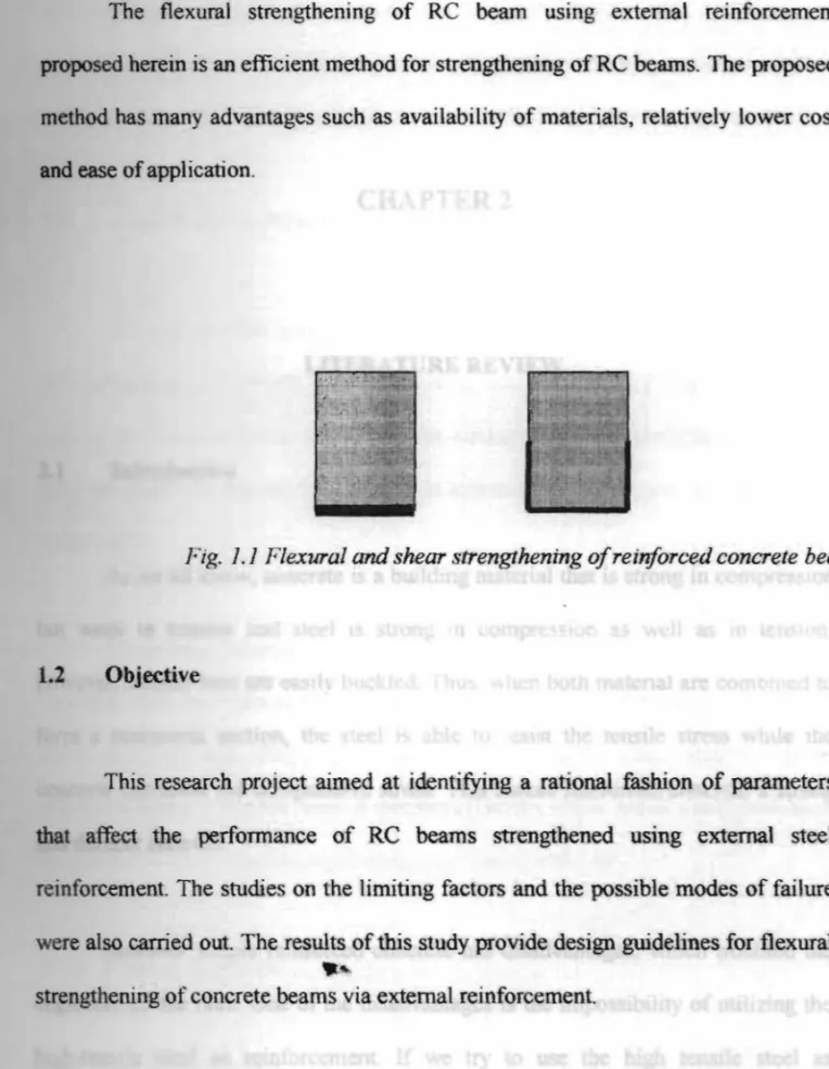
Fig. 1.1 Flexural and shear strengthening ofreinforced concrete beams.
1.2 Objective
This research project aimed at identifying a rational fashion of parameters
that affect the performance of RC beams strengthened using external steel
reinforcement. The studies on the limiting factors and the possible modes of failure were also carried out. The results of this study provide design guidelines for flexural
....
strengthening of concrete beams via external reinforcement.
CHAPTER 2
LITERATURE REVIEW
2.1 Introduction
As we all know, concrete is a building material that is strong in compression but weak in tension and steel is strong in compression as wen as in tension; however, slender bars are easily buckled. Thus, when both material are combined to fonn a composite section, the steel is able to resist the tensile stress while the concrete can resist the compressive stress. This makes reinforced concrete a strong and durable material.
However simple reinforced concrete has disadvantages, which troubled the .~
engineers a)) the time. One of the disadvantages is the impossibility of utilizing the high-tensile steel as reinforcement. If we try to use the high tensile steel as reinforcements, the resulting cracks in the tensile zone of the concrete become so wide, that the load-carrying capacity of the members will practically be lost. (Graduck, 1968)
Many researchers had carried out research to solve this problem. The researchers bad already proved that by using external prestressing and external fibre reinforced plastic (FRP) plates the flexural strength of RC beams can be increased.
2.2 Applications in Structural Strengthening.
External reinforcement of RC beams is mean, where the reinforcement is
located outside of the beam section. However external reinforcement is considered one of the most powerful techniques for strengthening or rehabilitating existing concrete structures despite the undesirable appearance, which can be treated in the later stage.
Historically, concrete members have been repaired by post tensioning or jacketing with new concrete in conjunction. with surface adhesive (Klaiber et al.
1987). Since the mid ]960'5, epoxy bonded steel plates have been used in Europe and South Africa to retrofit flexural members (Dussex 1987). Many researchers have studied the external reinforcement using prestressing and FRP.
2.2.1 External steel plate.
The major advantage of using steel plate is its high strength relative to the strength of the other common structural materials such as wood, masonry and concrete. Because of its high strength and also cost factors, reinforcement using steel plate is widely used in construction work of existing structures. Steel is composed of about 98% of iron with main alloying element carbon silicon and manages. Steel is
Pusat Khidmat M· kl
UNCVERSITI MAL<J y unmt Akadt.'fllik
. SIA SARAW K
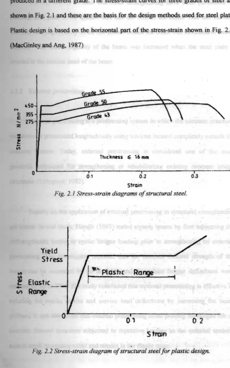
produced in a different grade. The stress-strain curves for three grades of steel are shown in Fig. 2.1 and these are the basis fOT the design methods used for steel plate. Plastic design is based on the horizontal part of the stress-strain shown in Fig. 2.2. (MacGlnley and Ang, 1987)
450 N
e
Co: ISS Z~ -Z tit..
t
...
Ci1 ThlcknH$ ~ 16 mmo
0·1 0.2 03 strainFig. 2.1 Stress-strain diagrams ofstructural steel.
Yield
Stress
Itit Ploshc Ra~
~
Elastic...
~RaI9
'"
,
r01
o
2
.
strain
.
Fig. 2.2 Stress-strain diagram ofstructural steel for plastic design.
For RC beams, flexural and shear strengthening have been perfonned by bonding steel plate to the tension face and the web of the beam. This can increase the load-carrying capacity of the RC beam because the beam was increased in tensile capacity. The tensile capacity of the beam was increased when the steel plate is bonded to the tension zone of the beam.
2.2.2 External prestressing
External prestressing is a prestressing system in which the concrete structural members are prestressed longitudinally using tendons located completely outside the concrete section. Today, external prestressing is considered one of the most powerful techniques for strengthening or rehabilitating existing concrete bridge structures (Virlogeux, 1982).
Reports on the application of external prestressing in structural strengthening are scarce. In one study, Harajll (1993) tested sixteen beams by first subjecting the unstrengthened beams to cyclic fatigue loading prior to strengthening by external prestressing. The investigator reported that the nominal 'flexural strength of the beams can be increased by u,to 146% and the induce fatigue deflections were reduced by up to 75%. The study concluded that external prestressing is effective in reducing the cracks widths and service load deflections by increasing the beam stiffness. It was also found that external prestressing could prolong the fatigue life of concrete flexural members subjected to repetitive loading as the external tendons sustain sma)J increasing stress and remain in the elastic stage.
Other study of strengthening of reinforced concrete beams by external prestressing is done by Tan K.H. and Ng C.K. (1995). Three externally prestressed
beams were tested and emphasis was placed on the provision of deviators at various
positions along the span of the beams. The investigators reported that the beams were strengthened by about 50%, demonstrating the effectiveness of external prestressing as a flexural strengthening method for normal RC beams.
One of the actual applications of structural strengthening via external prestressing is the rehabilitation of the multi-storey Pier concrete frame carpark in San Francisco.
2.2.3 External FRP plates
Fibre reinforced plastic (FRP) is an advanced composite material, developed originally for aerospace and defense applications, in the civil engineering and construction industry, based on their mechanical and chemjcal characteristics. FRP plates have been bonded to the tension face of reinforced concrete beams to increase the bending capacity of the beam. Experimental and theoretical studies on this type
of beam have shown a signihnt increase in the ultimate load and considerable
improvement in cracking behavior (Malek and Saadatmanesh, 1998).
The parametric study of beams with externally bonded FRP reinforcement 'is conducted to investigate the effects of FRP reinforcement on serviceability, strength
and failure mechanisms of repaired RC beams (Arduini and Nanni, 1997). The investigator reported that the ratio between ultimate linear load of the strengthened
beams and the ultimate linear load of un-strengthened one as a function of the FRP thickness.
Mu(strengthened)
J
=
t (Tn' k Ie ness)( M"" (Unstrengthened)
where Mu{strengthened) is strength of the strengthened beam; Mu{unstrengthened) is
strength of the unstrengthened beam; and 1 is the thickness of the FRP plate. FRP
with low modulus and high thickness gives the best performance even in terms of failure mechanism provided that shear strength near the supports does not become the controlling factors.
Many of the bridges in used in United States are strengthened with bonded FRP plates or fabrics. These bridges were never designed to carry the types of load and volume of traffic that they are currently called upon to do. Therefore, by using external FRPplates, the beams bad gained extra flexural strength to serve the purpose of increase in lQading.
1.J Failure Modes and Flexural Strength of Reinforced Concrete Beams.
When a reinforced concrete beam is loaded to failure, three modes of
bending failure are possible. The particular mode of failure is determined by the percentage of steel located in the tension zone. Two of these modes are brittle and one is ducnle. Since the designer's prime concern is to produce ductile beams with a high capacity for energy absorption, beams must be proportioned to ensure that only the ductile failure mode is possible (Kong and Evans, 1988).
Case 1. The beam is over-reinforced and the failure mode is a sudden, brittle failure, which the engineer must carefully guard against in design. When the over reinforced beam is loaded to failure, the failure is initiated by the crushing of the concrete followed by the sudden disintegration of the compression zone while the stress in the relatively large area of steel has not reached its yield point. To prevent a brittle failure, the reinforcement must yield while the strain in the concrete is less than the failure strain of 0.003 (AC3I8) or 0.0035 (BS811O).
Case 2. The beam has a moderate percentage of steel and the failure mode is initiated by a yielding of the steel while the strains in the concrete are relatively low. Such beams can continue to carry loads and are able to undergo large deflections before final collapse occurs; this ductile mode of failure is the only acceptable mode.
Casel. The beam is lightly reinforced with a very small percentage of steel, and the failure mode is also brittle. When the tensile stress in the concrete exceeds the modulus of rupture (the tensile strength), the concrete cracks and immediately releases the tensile force it carries; the lightly stressed steel must then absorb this increment of load. If the area of steel provided is too small to carry this added force, the steel will snap and total rup~of the section will occur suddenly.
To ensure ductile failures, upper and lower limits on the permitted area of reinforcing steel are established by the ACI and BSI code. The lower limit ensures that enough steel will be used to prevent the steel from snapping suddenly and causing the beam to split. The upper limit on steel area prevents the design of over reinforced beams. Since the presence of shear force has little influence on the
moment capacity of a cross section, shear is not considered in the design of members for bending.
2.4 Balanced Failure of a Beam with a Rectangular Cross Section.
To ensure ductile behavior and controlled failures, the ACI and BSI Code
permits only the design of under-reinforced beams. The maximum area of steel pennitted in a cross section can be developed from a consideration of the level of strain in the concrete at the instant the steel initially yields.
Ductility depends primarily on the magnitude of the maximmn strain in the concrete as the tension steel is stressed just to its yield point. If the strain in the concrete is small when the steel begins to yield, the beam can undergo considerable additional bending defonnation before the concrete is strained to failure. As shown
in Fig. 2.3, after the tension steel yields, additional moment applied to an under~
reinforced beam causes the neutral axis to move toward the compression surfaces. As a result, concrete strains increase less rapidly while the strains in the steel
increase more rapidly. Under hse conditions large deflection occurs and this is followed by crushing of concrete in the compression zone.