TRACKING VEHICLE IN GSM NETWORK TO SUPPORT INTELLIGENT
TRANSPORTATION SYSTEMS
Z. Koppanyia,* , T. Lovas a, A. Barsia, H. Demeterc, A. Beehareeb, A. Berenyia
a BME, Dept. of Photogrammetry and Geoinformatics, Műegyetem rkp. 3., 1111 Budapest, Hungary, {koppanyi.zoltan, lovas.tamas, barsi.arpad, berenyi.attila}@fmt.bme.hu
b
UCL, Gower Street, London WC1E 6BT, UK, A. [email protected]
cNokia Siemens Networks, Köztelek utca 6., 1092 Budapest, Hungary, [email protected]
Commission II, WG II/7
KEY WORDS: Positioning Services, Navigation, Mobile Networks, Vehicle Tracking, Accuracy Assessment
ABSTRACT:
The penetration of GSM capable devices is very high, especially in Europe. To exploit the potential of turning these mobile devices into dynamic data acquisition nodes that provides valuable data for Intelligent Transportation Systems (ITS), position information is needed. The paper describes the basic operation principles of the GSM system and provides an overview on the existing methods for deriving location data in the network. A novel positioning solution is presented that rely on handover (HO) zone measurements; the zone geometry properties are also discussed. A new concept of HO zone sequence recognition is introduced that involves application of Probabilistic Deterministic Finite State Automata (PDFA). Both the potential commercial applications and the use of the derived position data in ITS is discussed for tracking vehicles and monitoring traffic flow. As a practical cutting edge example, the integration possibility of the technology in the SafeTRIP platform (developed in an EC FP7 project) is presented.
1. INTRODUCTION
Positioning in intelligent transportation systems (ITS) is generally supported by GNSS-based solution. By receiving the signals from satellites (both from GNSS satellites and that of satellite-based augmentation systems, e.g. EGNOS in Europe), a device in the vehicle is able to calculate its geographic location. The GNSS-based positioning has three major shortcomings:
in case of limited satellite visibility, (e.g. in dense urban areas and tunnels), the receiver is unable to calculate its position,
not all vehicles are equipped with GNSS capable devices
in-vehicle GNSS capable devices generally do not share their location data with other devices and externally Alternative positioning technologies (the so-called dead reckoning systems) can support GNSS in case of signal loss. However this only addresses the first shortcoming.
Cell-phones and other mobile devices (e.g. tablets, laptops) can be found in almost all road vehicles. Mobile communication systems (e.g. GSM) inherently require knowledge of cell-phones‟ position in the network. Of course, the positioning accuracy can be considered as moderate, compared to that provided by GNSS, but it may be sufficient to support many ITS applications. The paper introduces the positioning technique by handover (HO) zone measurements. An investigation is presented on how the technology can support cutting edge ITS solutions – along with its potential use in the context of the EC FP7 SafeTRIP project.
2. GSM NETWORK
The GSM (Global System for Mobile Communications) technology is a personal communication service to provide connection between mobile devices. It is governed by an international standard developed by the European Telecommunications Standards Institute. The first specification was introduced in 1990 and has evolved ever since. The standard set includes the traditional circuit switched mobile communication as well as the packet switched standards, like
GPRS and EDGE. The specification was extended in order to support location services in 1999 (ETSI, 1999).
2.1 GSM Infrastructure and Operations
The coverage area of a GSM network is divided into cells. Transmission towers called Base Stations (BTS) determine the cells‟ locations and sizes. BTSs can be equipped with multiple antennas pointing in different directions. The area of the transmitted signals of these directed antennas determine sectors within each cell; each sector has a unique identifier, called Cell-ID (Figure 1). These cells are grouped into logical areas known as Location Area (LA). An LA has an integer identifier called Location Area Code (LAC) and has a Base Station Controller (BSC). The LA is an important means to control mobility in the network, as Mobile Stations (MS) are required to report their new position when moving from a LA to another. Neither large nor small LA is optimal from the network signalling point of view, so their size is optimized for minimizing signalling traffic. The smallest element of the GSM infrastructure is the MS (e.g. a cellular phone) with its SIM card. MS measures the signal strength of the surrounding BTSs/cells and can connect to BTSs. Neighbouring BTSs are connected to Base Station Controller (BSC). Each BSC usually belongs to an LA, and they are connected to Mobile Switching Center (MSC). MSC has a database called Visitor Location Register (VLR) that records the MS‟s LAC and connected phones‟ Cell-IDs within the area of MSC. In addition, the network has a global database that also contains the last known LAC and Cell-ID of MS, called Home Location Register (HLR). MSC uses HLR when the target MS is in another MSC.
When MS reaches another LA in idle mode (i.e. no on-going phone call or incoming SMS), it sends a request for changing its LAC. Therefore it measures signal strengths and observe actual BTS‟s LAC. The network is responsible for decision based on this request; if the request is approved, the changes are registered in VLR and HLR. This method is called Location Area Update (LAU).
Figure 1. GSM like cellular network
In connected mode (e.g. during a phone call) it is important to track MS movements at cell level; VLR and HLR record the MS‟s Cell-ID. When the moving user reaches the boundary of the cell, MS measures lower signal strength compared to other (neighboring) base stations. Therefore, MS sends a request to the network for changing its Cell-ID, and the network decides; if the network confirms it, the Cell-ID will be changed and the new base station will serve the MS. This operation is called handover event (HO).
2.2 Positioning Solutions in GSM Networks
GSM-based positioning techniques can be divided into two categories based on equipment requirements. Technologies in the first category do not need special equipment to determine MS‟s position (Cell-ID, RSS-based) on the network side. Those in the second category require hardware modules to support positioning. One such equipment is the Serving Mobile Location Center (SMLC), which controls network elements, gathers, processes and publishes information. Another hardware module is the Location Measurement Unit (LMU) which is integrated into BTSs, such that it measures signals from other BTS and/or MS for time synchronization.
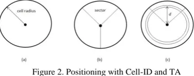
2.2.1 Cell-ID and TA: Each cell has a unique Cell-ID, and MS device can connect to only one cell at a time. If the coordinates and Cell-ID are paired, the MS position could be derived from these values (Figure 2a). A BTS position can be acquired on the fly if they are broadcasted – a functionality that is operator dependent. If the BTS uses directed antenna, the inference of the MS location can be more accurate (Figure 2b) by narrowing down to particular sectors. This method can be extended with distance measurement like Timing Advance (TA). TA is an integer value between 0-63 that determine the bit delay of MS transmitted signal in order to avoid collisions with other MSs‟ signals.
Figure 2. Positioning with Cell-ID and TA
2.2.2 RSS-based: MSs continuously measure BTSs‟ signal strength, called Received Signal Strength (RSS). The difference of Transmitted Signal Strength (TSS, which comes from BTS) and RSS is the signal loss. The signal loss could be determined with different signal propagation models (Green et al., 2002). If at least three coordinates of BTSs and the distance between these BTSs and MS are known, the MS position could be determined. If the distance errors are not taken into account, the circles around BTS positions with distance radius intersect each other in one point.
Another solution is the fingerprinting method. In this case off-line phase (i.e. learning mode) RSS information have to be
measured for all BTS in discrete points. These RSS vectors are saved in a database. In on-line phase (i.e. measurement mode) the MS also measures RSS vectors and compare these values with the ones stored in the database. The basis of comparison could be any norm or stochastic model (Ahriz et al., 2010). Using RSS-based positioning, there is no need for any special equipment from network-side.
2.2.3 Angle of Arrival (AoA): In this solution it is necessary to use special antennas in BTS that are able to transmit direction-dependent signals. After removing error effects on RSS (similar to the error effects of TSS), the azimuth of BTS and MS can be calculated (Deblauwe et al, 2007). If the angles of the two base stations and their coordinates are known, the vectors from BTSs intersect each other at MS position.
2.2.4 Enhanced Observed Time Difference (E-OTD): In case of E-OTD time frames are used to determine travel time of signals from the MS to multiple BTSs. Using the time differences, the position can be calculated using the signal speed (light speed). There are two different types of E-OTD: in the first type the time differences are calculated from differences of signals‟ travel time of different BTSs. This method is called hyperbolic E-OTD. If the BTSs‟ coordinates are known and the timestamp of the time frame is accurate, the time differences determine hyperbolas, which intersect each other in MS position. The system has to be equipped with LMU to provide appropriate timestamps. In the second type, the distance of MS and BTSs‟ are used, thus the time synchronization must be solved between these units. It is difficult to synchronize MSs‟ clocks, therefore these offsets are only estimated. The principle of positioning is the same as that of RSS-based solution. This technique is called circular E-OTD (Küpper, 2005).
2.2.5 Uplink-Time Difference of Arrival (U-TDoA): This is a network-based solution, where the dedicated BTSs and LMUs measure the MS‟s time frames of uplink channel in connected mode. The SMLC gathers the information and calculates the position with the same method that of hyperbolic E-OTD. In order to use U-TDoA in idle mode, the network has to generate fake handover events to force MS to answer (Küpper, 2005).
2.3 Advantage and Disadvantage of the methods
Each technique provides different level of positioning accuracy. Using special equipments (eg. SMLC, LMU), the positioning errors can be reduced, however their deployment comes at a cost and the change they introduce can put operator‟s network at risk. Thus AoA, E-OTD, and U-TDoA are not the best solution in some cases. On the other hand the Cell-ID-based techniques require low infrastructure costs and easily implemented, thus it can be the appropriate chose for extracting location data from network side. The comparison of these methods can be found in literature (Drane, 1998).
2.4 Evolutions and Future Trends
The mobile networks evolved from 2G (e.g. GSM), to 3G (e.g. UMTS) towards 4G (e.g. LTE). The 3G Universal Mobile Telecommunication System (UMTS) provides higher data rates for data connections and introduces a new mobility concept called soft handover. An active 3G MS can communicate in parallel with multiple cells called the active set. Whenever there is a candidate cell with stronger signal, it is added to the active set, and accordingly cells with weaker signals are removed from the active set. Multiple incoming signals are co-related in real
time, and used for error correction or voice quality improvement. Dealing with soft handovers requires new mobile localization methods. Although it is expected that 3G will replace 2G in future, currently both type of networks co-exist, and their localization methods will have to be supported, The 4G Long Term Evolution is a successor of 3G system and provides even higher data rates. Thus a clear trend of data communication taking over voice communication in the mobile networks can be observed. Mobile web application (e.g. email, chat, browser) require periodic network connection, generating data bursts in the network. Each of these data bursts, with appropriate method, can be converted into location information. As the number of these application and their data demand increases, data communication will play an essential means in localizing MSs in the mobile networks. The increased bandwidth can be supported with higher frequencies and smaller cell sizes. In this respect the resolution of location information based on HO is expected to be better in the future, especially in densely populated urban areas.
3. HANDOVER-BASED TECHNOLOGY FOR TRACKING VEHICLE
One major advantage of GSM-based positioning solution is that the position of the MS can be derived without any additional data exchange or application on the MS and there is no need of further hardware element installation on network side either. One potential positioning technology in GSM network is based on measuring the handover events.
3.1 Concepts
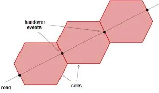
Moving MSs can cause handover events in connected and location update events in idle mode on the network side. LAU can be described with old and new LAC, in case of HO it is extended with old and new Cell-ID. This set of IDs can be called HO or LAC transitions. Events can occur, when the MSs reach the boundary of a cell or location area based on RSS measurements. Therefore these events will theoretically happen half way between two BTSs, which can be determined by a 2D Voronoi-diagram (Figure 1). As vehicles move, which is represented by lines in this model, they intersects this Voronoi-diagram in one point with a particular transition (Figure 3.). If the transitions are measured, it determines patterns on each road that the MS can follow in the vehicle. These patterns can be recognized on network side, thus vehicles trajectory can be calculated. With this information the speed, travel times, or location of vehicles can be determined.
Figure 3. Positioning with Cell-ID and TA
3.2 Examinations of HO event
In practice the events do not occur at same location due to parameters such as signal propagation, number of users in cell and network decision, etc. The following properties were examined to assess theirs impacts:
1. Type of MSs: Different phones detect different cells due to certain peculiarities of the hardware. To detect this effect Nokia E72, E71 and E51 mobile phones were compared. The results showed different HO behavior with large differences in some cases. It means that the phones do not follow one but several HO patterns when on the move. 2. Type of logging software: In measurement mode the HO
sequences can be detected on network side, but not in every case. Thus logging software to measure of the HO/LAU transitions have to be installed on MS. Two logging software - Nokia Siemens Networks‟ MQA (Mobile Quality Agency) and an open software called CellTrack - were examined on same MS. Due to differences in the software, 2-30 seconds of delays were detected between the logged data of different applications in HO recognition. In some cases the detected cell pattern was different.
3. Speed effects: On a road network, the speed of vehicles is different. It can be assumed that different speed will lead to different HO/LAU events. HOs were measured at three different speeds (30, 50, 70 km/h). While different HO behaviors were detected, the precise impact of speed could not be unambiguously determined due to presence of other effects.
These tests show that the HO cannot be determined as a point on a particular road. The same would apply to LAU which relies on a similar decision mechanism. The problem can be handled by modeling location as a zone that can be created as the convex hull of same HO/LAU points that called HO/LAU zone. In measuring phase the sequences (i.e. patterns) of HO and LAU zones can be determined and stored in database on each road. There are operating solutions and IPRs based on this concept; most of them estimate travel time with HO zones. Comparison of systems can be found in (Wunnava et al., 2007). It proves that these solutions provide appropriate travel time only when the traffic is nearly free flow. If the speed of the vehicles decreases, the accuracy of the estimation will decrease as well. In this paper a new concept of HO sequence recognition and interpretation of HO zone geometry properties is introduced.
3.3 Pattern of HO/LAU zones recognition
Based on the measurements, the sequences of HO/LAU transitions and their location for each road are stored in database. In on-line (i.e. in working environment) phase the HO/LAU were observed by MS or network. The likelihood of location of MS can be described with the following expression (Roos et al., 2002):
| | (1)
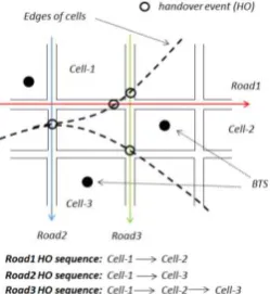
where is location, is observed HO/LAU. On the right side of the expression the | can be determined in the measurement phase, can be used as map matching function that is often identity distribution, and can be a scaling function. In database every observation can be mapped with an appropriate location value, collected during the measuring phase (i.e. | ). But the calculation of this pdf (probability distribution function) is ambiguous due to different road patterns, which can also contain same HO/LAUs. It is often occurred in case of road with different directions or in high population area (e.g. towns, cities), where are a number of crossing roads can be found (see Figure 4.). In this case vehicles can enter the given cell with same HO/LAU while moving on different roads. In order to estimate the appropriate road, several HO/LAU events of moving vehicles have to be
observed. It can increase the location probability, and can be expressed with following from Eq. 1.:
| | | | | | | | (2)
i.e. stochastic process and the | | | conditional probabilities can be modelled with Markov-chain. To identify the appropriate road, the observations can be matched with measured HO/LAU database. This is a pattern recognition problem that can be solved with probabilistic finite automata (PFA) because PFA is the general concept of Markov-chain (Dupont et al., 2004).
Figure 4. Short example and crossing road problem
PFA is a 5-tuple , where alphabet will be all observed LACs and Cell-IDs in measuring phase, is the set of states, which can represent BTSs, is a transition probability function, which is the HOs in this model with computed probabilities. are the initial and final probabilities of the states; final probabilities of the states will not be used. In our model, given state (IDs) indicate an unambiguously transitions. That means we assume that the HOs are unique on a given road, but part of HO sequences could appear in pattern of different roads with a given probability. In this case the simpler Probabilistic Deterministic Finite State Automata (PDFA) model can be used. Moving vehicle with MS generate a HO sequence, which is a word in this terminology. Let be a word that describes an HO sequence. If the PDFA is determined for each road, the probability of word can be calculated on the roads (i.e. , where is automata of the -th road). The maximum of the probabilities gives the appropriate road (i.e.
).
For learning automata (estimate probabilities of transitions), the maximum likelihood probability estimator could be chosen in this particular case (Dupont, 2004):
{
(3)
where is the probability of transition between and states with letter (i.e. the probability of HO), is the number of the given transitions that can be calculated from measuring phase, and is the sum of all transition from state. Using and determining automata in this way ensures that PDFA can be used not only as an acceptor but as a generator as well that is useful for other applications (modelling traffic, network tests, especially ad-hoc networks, etc.).
Figure 5. Example of appropriate road identification
Figure 5. shows an example of using PDFA to determine the appropriate road (based on the test case detailed in Figure 4). Different HO sequence can be derived from measurements that were done in different rounds. Note that the HOs do not happen deterministically. In case of Road2 the MS sometimes checks in Cell-2, in case of Road3 MS misses Cell-2, i.e. HOs behave probabilistic. From the measurements the PDFA can be created with Eq. 4. Right side of Figure 5 shows an example of observed HO sequences. Note that a great amount of HOs (states) is required to provide appropriate solution for the problem with the proposed method.
3.4 Geometry properties of zones
To characterize the accuracy of the handover-based solution it is necessary to describe the geometry properties of zones. The accuracy of a single zone can be defined with the area of the zone, its error ellipse, or the zone‟s point error. To calculate these parameters, measurements were done on a wide, 2x3 lane (with tram tracks in the middle) road in Budapest. 8 rounds with 3 different types of phones were measured that means 27 HO/LAU sequences. For positioning an external GPS receiver was used.
The error ellipses were calculated and are shown in Figure 6.a. Note that direction of the error ellipses are are equal to road direction. In road direction the errors are caused by the GPS and the HO/LAU events error, while perpendicular to the road direction only the error of GPS can be seen.
The point errors are also calculated in case of each zone. These values‟ mean is approx. 137 m with 198 m deviation.
Figure 6. (a) Error ellipses of HO zones (b) Distribution of numbers of HO in zones
For determination of zones‟ sequences (i.e. pattern) on road several measurements are needed. Each measurement increase the HO numbers of the zones. The distribution of these points is
calculated and gives a power-law distribution (Figure 6.b.). It means that the zones with lower HO numbers are often appeared in the system. For this reason, it is necessary to determine the appropriate round of measurements in order to reach appropriate accuracy.
4. APPLICATIONS USING GSM-BASED POSITIONING
4.1 Human mobility patterns
Nowadays almost everybody has a connected mobile device, thus an unambiguous link between an individual and the device can be assumed. Most of these devices use GSM network, therefore mass location data can be extracted from GSM network side. This information can be used to understand the human mobility patterns. Location is available in discrete time (when the location of the user is accessible), from these real data new theories of human mobility can be developed that can be applied in biology (e.g. spread of viruses), economy (e.g. customers‟ behavior), transportation (e.g. public transportation design), etc. (Gonzalez et al, 2007).
4.2 Commercial aspects
The data gathered from GSM network side could be analyzed from a commercial perspective. Certain methods in traffic engineering use the origin-destination (O-D) matrix. The O-D matrix describes the movement of the users between different areas. The main applications for applying O-D matrices are network and transportation planning, traffic volume estimation and traffic control; there are static and dynamic estimation methods to derive the O-D matrix. Static method uses historical data (i.e. measurements), dynamic solution requires real-time, dynamic data (thus the matrix reflects the actual state of the traffic flow) that can be provided by GSM-based data acquisition.
Using this information the origin of the customers of a particular commercial unit can be recorded and specific marketing strategy decisions can be supported e.g. adapting special customer needs. Another aspect would be the identification of the routes of the potential customers that could support the deployment of outdoor advertisement boards.
4.3 Intelligent Transport Systems (ITS)
A current trend in transport research is the shift from traffic flow simulation algorithm to real traffic flow measurements techniques. It is easy to imagine that vehicles equipped with On-board Units and access to a communication channel could act as mobile nodes on the road network providing a rich source of data about the traffic, environment and road conditions. Such information assists traffic managers to regulate effectively in order to maintain a good traffic flow and minimize the risk of road incidents. However, the major challenge for solutions based on this assumption is access to the On-board Unit and the data stored in it.
ITS usually apply two different sources of data: static and dynamic data. Moreover, ITS can be categorized in several ways, e.g. there are on-line and off-line systems. The solution presented in this paper focuses on the on-line systems that mostly apply dynamic data.
The main application field of these systems is to support decision preparation process or making particular decisions; some of the most relevant applications are navigation, traffic flow control (e.g. changing the signal plan of traffic lights). It is obvious that this kind of applications require accurate and frequently updated data about the traffic flow.
Traditional data acquisition technologies involve induction loops or optical sensors (e.g. cameras), however, the shortcomings of these technologies do not allow continuous data acquisition.
Induction loop(s) are built into the surface of the road, therefore it is highly vulnerable (e.g. due to dynamic load of the vehicles) and both its deployment and reparation requires at least partial road closure. On the other hand this data acquisition technique could provide reliable traffic count and lane occupation data. Optical cameras provide data about the current traffic flow, and the deployment and maintenance of this solution is relatively simple (i.e. does not require road closure). However, by limited visibility (e.g. fog, heavy snow- or rainfall) the optical technologies could not provide reliable.
With the GSM-based solution the most of the aforementioned shortcomings can be avoided. It is not affected by the weather and no optical visibility has to be ensured.
The solution presented in this paper does not require additional hardware or software on the network or on the client side, thus installation and maintenance are not required – this makes the solution transparent.
The main application of the presented technology is velocity estimation and therefore congestion detection. Using this technology, the capacity of the existing road network could be better exploited, thus the overall safety impact of transportation on the road network could be increased and the negative environmental impact could be decreased.
Besides the commercial aspects described in section 4.2, there is the possibility to analyse areas with high pedestrian/bicycle traffic, isolate dangerous nodes/road stretches or study frequent routes e.g. between major cities to decrease travel time.
4.4 SafeTRIP
The SafeTRIP project (Fremont et al, 2010) aims to build on this success and utilize a new generation of satellite technology to improve the safety, security and environmental sustainability of road transport. While being open and capable of integrating other communication technologies (such as Ground Networks), SafeTRIP operates over satellite on the S-band frequency range [ref] which is optimized for two-way communication for on-board vehicle units
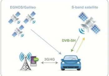
The SafeTRIP platform is being designed from ground-up to be an open platform. The SafeTRIP On-Board Unit (OBU, called „GreenBox‟) will offer an open API (Application Program Interface) that will allow third party applications to have access to functionalities of the GreenBox. In addition, a set of enabling services including VoIP (Voice over Internet Protocol), DVB-SH and GNSS localization (Figure 7), will be setup to provide a backbone for applications. By giving access to the communication infrastructure as well as enabling services, application developers can create new applications and services for the SafeTRIP platform.
Figure 7 - The SafeTRIP Concept
While the strength of SafeTRIP lies mainly in the use satellite communication (S-band for broadcasting, messaging and bi-directional links) and positioning technologies (GPS), they are also its potential weaknesses. Both technologies rely on clear visibility of the sky – and affected by environmental conditions described in previous sections.
GSM-based positioning would further strengthen the SafeTRIP proposition as a reliable and open platform for ITS – by providing a reliable alternative when satellite based technologies fail. Just as the SafeTRIP middleware abstracts the physical communication links (satellite, AGN, 3G) by providing a unified API for communication, the GPS-based positioning could coexist with the GNSS solutions – without any changes required in the applications. The middleware would use the best available option automatically. While the current implementation of SafeTRIP platform does not support this feature, the reference architecture is flexible enough to cater for alternative positioning modules.
An extensive user requirements capture was undertaken in the SafeTRIP project to understand the needs behind ITS services and how they could be supported. As it turns out the level of accuracy required by some ITS services are fairly coarse and therefore in spite of the occasional low-level accuracy obtained through GSM-positioning, coarse positioning is better than no positioning information.
The following are the key applications where low-level of accuracy is acceptable.
While travelling through unfamiliar areas across countries, private and commercial drivers would want to be reassured that their position can be determined if they require assistance either in case of emergency or breakdown.
Fleet managers would like to be able to reliably track Hazardous Goods Vehicle (HGVs) travelling across pan-European routes over 100s or 1000s of kilometres. In such cases, errors of 200-300 m are tolerable.
5. CONCLUSION
Based on our initial results, the novel GSM-based positioning method described in the paper can potentially support intelligent transportation systems. The method of mapping handover zones as network side data acquisition is easy to be implemented; there is no need for additional hardware deployment. Using probabilistic finite automata in handover zone pattern recognition enables improving route matching reliability and therefore supports various traffic flow applications. Method for assessing zone geometry patterns has also been developed. It has been investigated how this mass positioning data acquisition technique can broaden the area of location based services. Besides human mobility pattern mapping and potential commercial and intelligent transportation applications that could be based on origin-destination analysis, the paper provides detailed information on how this alternative positioning technique can be integrated in a cutting edge ITS platform SafeTRIP, and can be efficiently used as an alternative ground-based positioning method when satellite ground-based technologies fail or as a complementary method to improve accuracy or validate positioning information from GNSS systems.
6. REFERENCE
Ahriz, I., Oussar, Y., Denby, B., Dreyfus, G., 2010. Full Band GSM Fingerprints for Indoor Localization Using a Machine Learning Problem, International Journal of Navigation and Observation, vol. 2010, Article ID 497829, 7 pages, DOI:10.1155/2010/497829
Drane, C., Macnaughtan, M., Scott C., 1998. Positioning GSM telephones, Communications Magazine, IEEE, Vol. 36, pp. 46-54, 59
Dupont, P., Deins, F., Y. Esposito, 2004, Links between probabilistic automata and hidden Markov models: probability distributions, learning models and induction algorithms, Pattern Recognition, Vol. 38, No. 9. (September 2005), pp. 1349-1371
Gonzalez M. C., Hidalgo C. A., Barabasi, A. 2007. Understanding individual human mobility patterns, Nature, 779-782 (5 June 2008), DOI:10.1038/nature06958
Roos, T., Myllymäki, P., Tirri, H., Misikangas, P., Sievänen, J., 2002, International Journal of Wireless Information Networks, Volume 9, Number 3, DOI: 10.1023/A:1016003126882, pp. 155-164
Küpper, A., 2005. Location-Based Services: Fundamentals and Operations. John Wiley & Sons Ltd., GB,pp. 185-221.
Brida, P., Cepel, P., Duha, J., 2006. The Accuracy of RSS Based Positioning In: GSM Networks, Microwaves, Radar & Wireless Communications, 2006. MIKON 2006. International Conference, pp. 541–544.
Deblauwe, N., Van Biesen, L., 2007. An Angle Of Arrival Location Estimation Technique for Existing GSM Networks, In: Signal Processing and Communications, 2007. ICSPC 2007. IEEE International Conference, pp. 1527-1530
ETSI TS 101 724: “Digital cellular telecommunications system”, V8.4.0, December 2001.
Green, M. P., Wang, S. S., 2002. Signal Propagation Model Used to Predict Location Accuracy of GSM Mobile Phones for Emergency Applications In: Radio and Wireless Conference, 2002. RAWCON 2002. IEEE, pp. 119-122.
Fremont, G., Grazzini, S., Sasse, A. and Beeharee, A. (2010) The SafeTRIP Project: Improving Road Safety for Passenger Vehicles using 2-way Satellite Communications. In Proceedings of ITS World Congress 2010, Busan, Korea, Oct 25-29, 2010
Wunnava, S., Yen, K., Babij, T., Zavaleta R., Romero, R., Archilla, C., 2007. Travel Time Estimation Using Cell Phones (TTECP) for Highways and Roadways, Final Report Prepared for the Florida Department of Transportaion.
ACKNOWLEDGEMENT
This work is connected to the scientific program of the "Development of quality-oriented and harmonized R+D+I strategy and functional model at BME" project. This project is supported by the New Hungary Development Plan (Project ID:
TÁMOP-4.2.1/B-09/1/KMR-2010-0002).