3D BUILDINGS EXTRACTION FROM AERIAL IMAGES
O. Melnikovaaand F. Prandib
a
Czech Technical University, Zikova 4, 16 6 36, Prague 6, Czech Republic - [email protected] bFondazione Graphitech, Alla Cascata 56/C, 38123, Povo-Trento, Italy - [email protected]
KEY WORDS:Buildings Detection, Rooftop Hypothesis, Image Matching, Features Extraction
ABSTRACT:
This paper introduces a semi-automatic method for buildings extraction through multiple-view aerial image analysis. The advantage of the used semi-automatic approach is that it allows processing of each building individually finding the parameters of buildings features extraction more precisely for each area. On the early stage the presented technique uses an extraction of line segments that is done only inside of areas specified manually. The rooftop hypothesis is used further to determine a subset of quadrangles, which could form building roofs from a set of extracted lines and corners obtained on the previous stage. After collecting of all potential roof shapes in all images overlaps, the epipolar geometry is applied to find matching between images. This allows to make an accurate selection of building roofs removing false-positive ones and to identify their global 3D coordinates given camera internal parameters and coordinates. The last step of the image matching is based on geometrical constraints in contrast to traditional correlation. The correlation is applied only in some highly restricted areas in order to find coordinates more precisely, in such a way significantly reducing processing time of the algorithm. The algorithm has been tested on a set of Milan’s aerial images and shows highly accurate results.
1 INTRODUCTION
The buildings extraction from aerial images is widely used in dif-ferent areas such as cartography, photo-interpretation, urban and mission planning, placement of communication resources, and others. We can easily detect buildings and other objects on im-ages just by going through it by eyes. But in spite of this fact to realize this process by machine and acquire buildings global co-ordinates is complicated since the following problems are arisen:
• Object recognition: the objects of interest should be seg-mented from the background;
• Object reconstruction: the fragmented line segments of objects need to be grouped into meaningful structures, ac-quiring of buildings global coordinates.
Therefore, there is no universal automatic or semi-automatic ap-proach for buildings extraction. Commonly it is done manually in order to acquire precise results. It is important to take into consideration that the objects of interest could be partially oc-cluded by trees, shadows and other objects. These circumstances complicate a fully automatic solution of above problems. Others difficulties are caused by presence of texture of vegetation and variety of details located near the objects of interest that can be detected as buildings. Moreover, lines and corners of objects are often fragmented and missed due to the typical failures of low level features extraction.
All above problems have been solved previously in different ways (Section 1.1) but mostly for ”simple” scenes where buildings on images were presented as squares without occlusions and addi-tional elements on roofs. Most of their results can be used only as an initial approximation to the final building. Thus, the goal of the current research is to simplify the manual work and to de-velop a method for buildings detection and 3D reconstruction that could produce the global coordinates of buildings in a reliable way. Moreover, acquiring of accurate results costs great compu-tational efforts. Therefore, in the current approach images are processed in a semi-automatic way that allows reaching precise results including detection of complex structures (Mayer, 2007).
1.1 Related Work
Nowadays a considerable progress is reached in the area of build-ings detection from aerial images, which results can be effectively utilized for the rectilinear structures of urban areas.
An approach proposed by Mohan et al. (Mohan and Nevatia, 1989) found on detecting and reconstruction of 3D objects in complex scenes using perceptual grouping. They introduced a term ”collated features”, that identify those structural relation-ships that characterize objects of human visual domain and re-main invariant with changing viewing coordinates. The choice of collated features depends on the problem domain and system goal, and in the presented approach is determined by the generic shape of the desired objects in the scene. First, all reasonable fea-ture groupings are computed, and then the most promising can-didates are selected by a constraint satisfaction network. Since in this approach all extracted line segments in the image are pro-cessed, the computation is highly time-consuming.
Noronha et al. described an approach (Noronha and Nevatia, 2001) using hypothesis and verification paradigm based on ceptual grouping. Hypothesis is generated by a hierarchical per-ceptual grouping process and verified by the evidence of visible walls and expected shadows. In order to make such verification the authors assumed that illumination falls directly from the sun, whose position is possible to compute from the imaging data and time, and shadows fall on the ground of a known height near the buildings. But the system needs to make several decisions in the selection and verification process based on simplicity and intu-itive judgments.
The research presented in this paper investigates an algorithm for buildings based on a ”rooftop hypothesis” that is relied on a method described by Dong-Min Woo et al. (Woo et al., 2007). Their approach is aimed to detect flexible connections between corners, such as rectilinear rooftops with L- and T-junctions. The current algorithm is able to detect rectilinear rooftops as well, but constructing these rooftops from two and more quadrangles. In order to detect all L-junctions the algorithm is based on a list of ”missing points” (Section 2.2), allowing to collect all potential parts of the rooftops, in contrast to approach (Woo et al., 2007), where only the nearest corner to the initial one is considered as potential. Their approach has been tested and results show that in case of any details on a roof, even small roof’s texture, the shape is detected not accurately.
2 CURRENT APPROACH
In this section we present the approach followed in the work, which consist ia a semi-automated algorithm for bulding extrac-tion and reconstrucextrac-tion from stereo-pair aerial images. The gen-eral consideration is that it is very complicated to determine the whole series of parameters, which take into account all different typologies of buildings and all various possibilities of lighting and occlusions in aerial images. For these reasons we propose a semi-automatic approach, wihch is oriented to work locally in areas selected by the user. The whole algorithm is divided into four main steps. The first step represents image preprocessing in order to increase a quality of images. The second step in-cludes feature extraction where 2D line segments are generated, and rooftop hypothesis is used to identify all possible quadrangles that may be parts of building roofs. All lines that are not involved in any roof shape are discarded, and as an output of this step an array of 2D coordinates of potential buildings for each image is generated. The next step represents the image matching where buildings correspondence is found between images, this allows obtaining an array of buildings’ 3D coordinates from 2D ones. Buildings’ shapes that do not have correspondence in other im-ages are removed from the list of buildings’ shapes. The last step is a 3D buildings’ reconstruction that visualizes a 3D buildings’ model.
2.1 Image Preprocessing
The entire image preprocessing and feature extraction steps are applied only to areas specified manually, in such a way reducing a processing time and allowing to find the parameters for the line extraction more precisely for each area. The performance of the image processing and the accuracy of the building shapes detec-tion depend mostly on the quality of the images and the quantity of information being carried by them. Thus, image preprocessing is aimed to reduce an amount of noise and increase a contrast of the image in the early stage of the processing in order to simplify further steps, such as edge detection, 2D lines generation.
In the current implementation the reduction of noise is reached by applying a 2D Gaussian smoothing filter with window size equal 3; and the contrast is enhanced locally by a Wallis filter.
2.2 Feature Extraction
After the quality of the image is improved, we apply an edge detector. It is aimed to identify the boundaries of homogeneous regions in an image based on properties such as intensity and texture. In the current research we use a Canny edge detector (Canny, 1986).
When the edges are detected it is required to find straight lines throughout the image in order to determine potential edges and corners of the buildings. We obtain an array of straight lines by a Hough transform, a standard method for finding primitives forms that are in the present case the straight lines.
If straight lines are available it is possible to find potential corners of buildings as an intersection of two line segments. In this work we test to identify two roof types: a square roof where corners an-gles have to be equal to90◦; and a ridge roof where three corners can form triangle or trapezoid. But due to a failure of the Canny edge detector to identify ridge elements of the roofs the second roof type has not been processed successfully. Therefore, the cur-rent study is concentrated mainly on square roofs, and further we will take into consideration only this type of roofs. According to the criteria of angles degree a number of found corners can be limited, thus the angle of lines intersection should be from70◦ to110◦, taking into account a perspective and a distortion of the images.
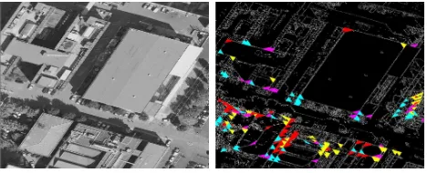
After collecting of all potential corners four types of corners are defined (Woo et al., 2007). Each found corner is labeled accord-ing to its orientation as it is shown in Figure 1, a. Figure 2 shows the result of the corners detection with corners labeling by colors.
Figure 1: a) corners classification; b) complex structure with a missing point for corners 3 and 4
Figure 2: Corners detection. Left: original image; right: corners detected and colored according to the classification
The next step is buildings shapes detection. The process is based on a rooftop hypothesis (Woo et al., 2007). The rooftop hypoth-esis is the rules of grouping the collected corners that are stated according to the labeling (Figure 1), and line segments in quad-rangles. Two corners can be connected only if they satisfy the corner relation conditions that are called collated features (Mo-han and Nevatia, 1989). According to the collated features an angle between two edges of different corners should be less than
5◦(ideally they should lie on the same line); in this case the cor-ners can be linked to each other.
• a simple one, which roof contains only one quadrangle;
• a complex building, which is constructed from two and more quadrangles.
The type of a currently processing building should be specified mainly.
Applying the collated features, a pair to each corner is deter-mined, that are corners lying on the same line with current corner. At least one pair for each edge of the current corner is required to be found from the list of all potential corners, otherwise the corner has to be deleted from the list of the potential corners. If there is one and more pairs to each edge a list of pairs is collected so that it would be possible to verify whether these linked corners are actually able to form a quadrangle after the linking. For ex-ample, using the corners classification for Figure 1, a, one list of pairs for a corner 1 will contain all corners with the label 2 that lie on the same line, and another list will include corners labeled with 4.
If the structure of the building is simple, verification is done by taking two corners from different lists of pairs for the current corner and searching an intersection of two edges of these cor-ners. After the intersection point is found the next step is looking for a corner that is in the list of the potential corners and lies in some specified range of this point. Thus, in the presented exam-ple if current corner is 1, then two corners from different lists of pairs are taken, i.e. 2 and 4 (Figure 1, a). In the range of the edges’ intersection of these two corners, corner with label 3 will be searched. If such corner is not found the next pair is taken for verification, otherwise the verification of the sum of all four corners on equality to360◦should be done. If this criterion is sat-isfied, then opposite edges of the found quadrangle are checked for equality.
Therefore the edge between corners 1 and 4 has to be equal to one between corners 2 and 3. If all criteria are fulfilled the pro-posed approach verifies the presence of edges found during the edge detection between each corners pair of the quadrangle. This operation is the most time-consuming in comparison with all pre-vious steps of verification, and thus should be done as the last one. In case of a satisfaction of all criteria the quadrangle is con-sidered as a roof.
If the structure of the building is complex the same rules of the verification are applied as for the simple one. But in case if in the range of the intersection point of two corners no corner is found, then this point is included in a list of missing points and the quadrangle is considered as a part of a potential roof. Coordi-nates of the intersection point and the label of the corner that has to be found in the place of this point in order to form a quadrangle are stored in the list of the missing points. If during the further verification any quadrangle ”misses” a corner with the same co-ordinates as one of the point listed in the missing points list, and the missing corner is adjacent with the listed one, then the cur-rent quadrangle and potential one (that has the missing corner with the same coordinates as current one) are considered as parts of the same building structure.
Consider a situation of a missing point for two quadrangles illus-trated in Figure 1, b. The upper quadrangle is found first but a cor-ner with labeling 3 is not detected. The labeling of the corcor-ner and its coordinates are saved in the missing points list, and the corner is considered as potential. The algorithm searches for the next quadrangles. The lower one is found but a corner 4 is a missing. Then the verification procedure checks the list of missing points
and finds that there exists a corner with the same coordinates in the list. The corners 3 and 4 are adjacent therefore the lower and upper quadrangles could be parts of the same structure. Both quadrangles are passed for the next verification step, i.e. image matching.
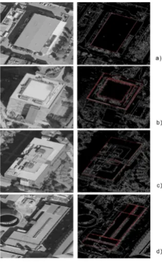
The results of the buildings detection are demonstrated in Figure 3 that are marked by red color. Figures 3, b and c show that on the step of building detection some shapes caused by noise or some small objects could be found that should be removed later. Figure 3, d presents a result of complex building detection.
Figure 3: The results of buidings detection
2.3 Image Matching
Since we process multiple-view aerial images, and internal cam-era parameters, such as a focal length, coordinates of a principle point, and camera coordinates are given, we are able to recover 3D buildings information using image matching. The concept is based on searching a corresponding point in one image for a given point in the second image using collinearity equations. Us-ing these equations it is possible to find for a point in one image an equation of a line where a correspondent point in the second image lies. This equation is called epipolar line equation.
But this verification does not guarantee that the found building from the second image corresponds exactly to one from the first image. The problem occurs when buildings are located close to each other, have the same size, and their corners lie on the same epipolar lines. Therefore we introduce two geometrical constraints that allow making precise selection of correspondent shapes. First of all, Z-coordinate of the object-space point (height of buildings) should be lower then some value; and Z-coordinate of all corners of a building should be the same (or have a dif-ference within some limits). These constraints allow determining corresponding buildings without false-positive identifications. The result of image matching is presented in Figure 4. According to the current algorithm the matching is done only from the first im-age shapes to the second one. The first found rooftop shape in the second image that satisfies all geometrical criteria is taken as a correspondent shape.
Figure 4: Result of image matching. a) left image after build-ing detection marked by red color; b) right image after buildbuild-ing detection marked by red color; c) result of image matching is marked by red color
As an extension of the algorithm described above, an optional and last step of the verification could be analyzing of an area around corners of the correspondent shape. Therefore the sec-ond image is correlated with templates of shape’s corners from the first image within some limited area around building’s cor-ners in the second image. A point with highest level of matching is taken as correspondent one. This allows finding the correspon-dent point more precise and getting much more accurate results (Tables 1, 2). Moreover, with such verification the ”strict” geo-metrical constraints are not required anymore, so it is possible to use the constraints with lower limits, since this template matching step reveals the most correspondent point in the second image.
# Original Z(m)
Z-coordinates for 4 corners of a building (m)
1 145.8 145.2 146.7 146.6 146.3
2 142.7 143.0 143.1 142.9 142.9
3 151.5 180.0 179.6 179.2 179.7
4 148.0 149.7 147.9 148.1 149.1
5 177.7 —– —– —– —–
6 150.6 150.3 150.3 149.4 150.0
7 144.6 145.2 143.2 144.2 145.2
Table 1: Comparison of Z-coordinate resultswithout correlation stepfor set of buildings (Figure 5)
One can see comparing Tables 1 and 2 that the building 5 has not been detected at all without the correlation step. Building 3 has been detected partially, but the difference between coordinates without the correlation step and maps ones is about 30 m, while the algorithm with the correlation step gives accurate results with
# Original Z(m)
Z-coordinates for 4 corners of a building (m)
1 145.8 145.9 146.4 146.4 145.3
2 142.7 143.0 142.4 142.1 142.9
3 151.5 151.6 151.3 150.9 151.4
4 148.0 147.5 148.2 147.8 147.8
5 177.7 178.3 178.2 177.5 178.3
6 150.6 150.5 150.6 151.1 150.0
7 144.6 144.3 143.8 144.3 144.6
Table 2: Comparison of Z-coordinate resultswith correlation stepfor set of buildings (Figure 5)
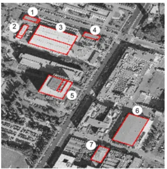
Figure 5: The numeration of buildings for Tables 1, 2. The result of image matching is marked by red color
the mean squared error less than 0.42 m. Thus, the current al-gorithm includes this verification step that significantly increases the accuracy of the method. In the current implementation the size of template equals to 11 pixels, and the area around the cor-ners equals to 99 pixels.
The result presented in Figure 5 makes possible to analyze the reliability of the matching. As one can see, this step removes all shapes constructed by noise, and the matching output is only shapes that belong to the building structures. Shapes are detected exactly on the lines of buildings shapes.
The output of the entire image matching procedure is global co-ordinates of the buildings, as top parts of buildings as bottom ones stipulating that approximate height of buildings is given. Buildings global coordinates allow us to construct a 3D buildings model.
3 CONCLUSION
However, it is naturally much more could be done. First, we would like to improve the edge detector since currently we are not able to detect ridge roofs. Second, it is possible to investigate new methods for detecting more types of building structures, as currently only some set of structures can be detected due to lim-itations of the principle of missing points. This principle can be extended in order to overcome the limitations. Finally, usage of different data sources such as LiDAR will allow reconstruction of the 3D buildings model in more details.
ACKNOWLEDGEMENTS
Olga Melnikova was supported by EC project FP7-ICT-247022 MASH and by Grant Agency of the CTU Prague project SGS10/069/OHK3/1T/13.
REFERENCES
Canny, J., 1986. A computational approach to edge detection. IEEE Transactions on Pattern Analysis and Machine Intelligence p. 679714.
Jaynes, C., Stolle, F. and Collins, R., 1994. Task Driven Per-ceptual Organization for Extraction of Rooftop Polygons. IEEE Workshop on Application of Computer Vision.
Mayer, H., 2007. Object extraction in photogrammetric computer vision. ScienceDirect. International Society for Photogrammetry and Remote Sensing.
Mohan, R. and Nevatia, R., 1989. Using Perceptual Organiza-tion to Extract 3D Structure. IEEE Trans. Pattern Analysis and Machine Intelligence.
Noronha, S. and Nevatia, R., 2001. Detection and Modeling of Buildings from Multiple Aerial Images. IEEE Transaction on Pattern Analysis and Machine Intelligence.