Development of Security System using Facial Recognition.
O.T. Arulogun
1, E.O. Omidiora
1, O.M. Olaniyi
2*, and A.A. Ipadeola
3.
1
Computer Science and Engineering Dept., Ladoke Akintola University of Technology, PMB 4000, Ogbomoso, Nigeria.
2
Department of Electronic and Electrical Engineering, College of Engineering, Bells University of Technology, Ota, Ogun-State, Nigeria.
3
Mechanical Engineering Dept., Ladoke Akintola University of Technology, PMB 4000, Ogbomoso, Nigeria.
*
E-mail: [email protected]
[email protected] [email protected]
ABSTRACT
Security is generally a state or feeling of being
saved and protected, an assurance that
something of value will not be taken. This paper employs two of the emerging artificial intelligence technologies: Facial Recognition and Artificial Neural Networks for developing a secure keyless door where authentication of authorized faces are the only guarantee for entry. This mechanically built door, with a camera, has an interface with the PC for capturing and processing images.
(Keywords: security, centronic port, PC, personal computer, interface, electromechanical systems,
surveillance system)
INTRODUCTION
The word security has been described in its contextual form as the freedom or protection from danger or worry; preventing spies, attacks and thefts. Security has been described in many ways depending on the area which is been put into consideration. For example, the way a military base will look at security might be different from how a stock brokerage firm describes its own security term. Considering all these point of views, the security state of any organization or individual brings about a feeling of happiness and peace of mind.
Different security inventions has evolved in these past few years, despite these various inventions, this area of the world is still lacking behind in implementing some or any of these sophisticated security measures because simple tools are used
for safeguarding lives and organizational
properties in developing countries such as Nigeria. These primitive tools are not only inefficient but also time consuming and life risking.
Considering all the numerous ill fated cases relating to security lapses in organizations, the ease and benefits of computer based security devices has brought the use of computer controlled security door systems into the modern vocabulary. This security system can also be regarded as an automated security door system. This can be used to achieve a sophisticated security system (SSS). Recent research works have shown that different human characteristics like finger prints and voice tags have been used for the development of an automated security door system but further studies have shown that a SSS can be developed using facial recognition systems.
This paper practically presents how an automated security door system can be controlled and implemented using the recognition capability and programmability of a computer system. A digital computer system has the power to compare different facial images with the aid of a good facial recognition algorithms coded into programs.
OVERVIEW OF FACIAL RECOGNITION AND ARTIFICIAL NEURAL NETWORK TECHNIQUES
All face recognition techniques can be categorized
into two major groups which are 1) geometric
based techniques and 2) template based techniques. In the first category the commonly used techniques are the elastic bunch graph matching approach and active appearance model [3].
The elastic bunch graph matching approach takes into account the human face features and uses elastic bunch graphs to automatically locate the fudicial points on the face (eyes, nose, mouth etc) and recognize the face according to these features [14]. The template based technique uses the eigenfaces which is developed from the knowledge of artificial neural network. It is based on Karhunen-Loeve transformation which is
otherwise known as principal component
analysis (PCA) [8]. This technique is often being used and it has become a defacto standard and a
common performance benchmark in face
recognition [10].Some other template based techniques include the linear discriminate analysis (LDA), Fisher face, Bayesian face recognition, discriminate eigenface, etc.
Artificial neural network has come a long way in developing the works and creativity of artificial neuroscientist. It involves parallel computing devices consisting of interconnected simple processors. It is basically an attempt to simulate specialized hardware and sophisticated software [1]. Multiple layers of simple processing element
are called neurons and each of them is
connected to each other with varying coefficient of
connectivity that shows the strength of
connections. Learning is accomplished by
adjusting these strengths to cause the overall network to output appropriate result [5]. There are a number of learning algorithms have been tested and trusted to be efficient over the years
THE PARALLEL PORT CONTROL
Parallel ports are PCI card ports which are basically being used to connect the computer to the printer. The personal computer (PC) sends data to the printer through the parallel port in 8 bits at every point in time and these bits are transmitted parallel to each other as opposed to the mode of operation of serial port. It is known that parallel ports are capable of transmitting 50 to 100 kilobytes per second which simply shows that parallel port communication depends on the operation of the computer system [2].
Most of the external devices like electrical, mechanical and electromechanical devices that computer controls in recent time is being done through the parallel port of the PC and this is
otherwise known as hardware interfacing.
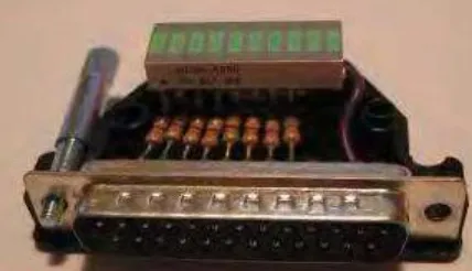
Hardware interfacing is simply the act of enabling communication between designed hardware and digital computer. This interfacing is usually done on most occasions through the port cable, one end of the cable is plugged into the parallel port on the computer system and the other end is connected to the hardware to be interfaced for the communication process to ensue. Figure 1 displays the configuration of the pins of the cable and the internal circuitry of the ends of parallel port cables.
Figure 1: Parallel Port Snapshot showing the 25 Pins and Internal Circuitry.
appear at the pins of the parallel port as a 5 volt supply at the pins. Lines/pins at the parallel port are classified into different categories which are:
1) data lines (pins P2-P9 on the parallel port) and
are denoted by D0-D9,
2) control lines (pins P1, P14, P16 and P17 on the
parallel port) and are denoted by C0– C3 (C4– C7
are not represented on the parallel port there is no internal register provided for them) which means that only 4 control pins are present in the parallel port,
3) status lines (pins P10, P11, P12 P13 and P15 on
the parallel port) and they are denoted by S3 – S7
which means that there are 5 basic status lines and finally we have the grounds which are pins P18– P25 [2].
Programming the parallel port can be done through the use of programming languages like VB®, VB.NET®, C#®, C++®, MATLAB®, etc. They are all user friendly and can be used to perform any task required by the user therefore
they are regarded to be user mode programs.
User mode programs lack basic functionality like direct communication with parallel ports and multithreading especially in this present age where the operating systems invoke (WIN NT4®,
WINXP, WIN2000, etc.) are security conscious.
So, there is what is called kernel mode driver which help the users‟ mode program to
communicate with the external devices through the parallel port without any kind of restriction. Kernel mode program runs in ring3 mode and simply solve the problem of reading and writing data to parallel port and let user mode program to communicate with it. Some of the examples of kernel mode drivers that exist are inpout32.dll, Ntportlibrary, Vitport, hwintaface.dll and IOPORT.ocx [2].
THE SYSTEM DESIGN
The entire system can be said to be in three segments seamlessly integrated together, these segments are:
Electro-Mechanical segment: This is responsible for all mechanical process like opening and closing of the door.
Electrical segment: This is responsible for mechanical signal conversion, mainly interface circuit.
Application Software segment: Bridges the gap between the user and the entire system. It also acts as the system controller.
The application is designed to accept data from the digital camera which serve as the input to the application. Aside the fact that this segment is accepting input data from the camera it does some other things such as:
Facial Image Creation: Create new user image in the database.
Facial Image Recognition: The images
captured by the application are
compared with the stored images in the database. This is to ensure such a user is an authorized user in this environment.
Authorization: This is the process of granting access to authenticated user.
PROGRAM STRUCTURE
The developed control program comprises of modules or sub-programs such as: training
procedure, comparison and recognition
procedure, error reporting procedure, and clearing sub-program and the main program that brings all the procedures together. The functions of each sub-program are explained:
FUNCTIONAL OBJECTIVES OF THE CONTROL PROGRAM
The following are the operations performed by the control program:
1. Creates a database of images of persons that has access to the restricted area.
2. Senses that an image has been taken by the digital camera.
3. Retrieves the image from the digital camera.
and determines if it exists in the database.
5. If it exists it sends a signal through the parallel port to the interface circuit of the mechanical sliding door.
6. Controls the movement of the mechanical sub-system in both the forward and reverse direction.
THE MAIN PROGRAM (Application software)
Since the security system designed using facial recognition is meant to be a real time process, the software module is designed to automatically perform operations and it is always running as expected unless it is halted by an administrator or when maintenance is to be done on it or its database of images.
The main program is written in MATLAB® as expected and it is driven by a timer function. The main program is written in such a way that it checks the digital camera every three seconds to adequately inform the necessary sub-program that an image has been taken by the camera. Any moment an image is detected in the camera, the face comparison and recognition sub-program goes to work.
The algorithm for the main program is as follows:
1. Start.
2. Check if database exists.
3. If database exist go to 4.
a. Else; create database (i.e., run face training sub-program).
4. At every 3 seconds check camera connection through USB port.
5. If camera is not on then run halt (i.e., error reporting sub-program); go to 4
a. Else go to 6.
6. Check camera memory.
7. If there is image in camera memory then read image.
a. Else write “no data found” go to 6.
8. Match image (i.e., run face comparison and recognition sub-program).
9. Run clearing sub-program.
10. Go to 4.
11. Stop on request.
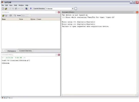
Figure 2: MATLAB® Application Software Interface.
THE FACE TRAINING SUB-PROGRAM (Algorithm)
The control program is been developed in such a way so that when it is started, the first process that takes place is checking to see if a database exists and if it does, checking to see if it has been updated. In a situation where the program is run for the first time; no database exists so this part of the program builds the required database and trains the faces contained in the database for the control program to operate. This training is done using Artificial Neural Networks. This has been explained in the earlier part of this work. During the course of operating this program, if there is cause for the database to be updated, a checkup on a file in the control program folder named database.mat is performed, then data is added/removed as the case may be to/from the folder containing the faces being used. Then control program will then start all over again. The program will automatically build another database and update it as required.
The algorithm for the face training sub-program is as follows:
2. Get each image and store it in a vector of size N.
3. Calculate the mean image; which is a column vector such that each entry is the mean of all corresponding pixels of the training images.
4. Center each of the training images by subtracting the mean image from each of the training images as shown in the Equation (2).
5. Create data matrix by combining the centered training images side by side into a data matrix of size NxP, where P is the number of training images and each column is a single image as shown in Equation (3).
6. Create covariance matrix by multiplying the data matrix by its transpose as shown in Equation (4).
7. Compute the eigenvalues and
corresponding eigenvectors for the
covariance matrix. V V (5)
8. Order the eigenvectors V i v
to their corresponding eigenvalues from high to low.
a. Keep only the eigenvectors
associated with non-zero
eigenvalues.
9. This matrix of eigenvectors is the
eigenspace V,where each column of V is
an eigenvector.
10. Stop.
THE FACE COMPARISON AND RECOGNITION SUB-PROGRAM (Algorithm)
The first process is the detection of a face in the digital cameras memory or building of the database in case of first time of running of the control program. After this, the program retrieves the face and the next process is performed by the face comparison and recognition sub-program. The face is compared with the faces in the database and if it is seen to exist then the program sends the required signal through the parallel port to the interfacing circuit, this triggers the operation of the electronic control circuit which produces the required voltage to the mechanical motor.
The DC motor, on receiving the required voltage, gains the necessary power to go into motion and thus moves in the reverse direction and opens the mechanical sliding door, granting access to the person at the door. If, on the other hand, the face is not recognized as being in the data base, the program reports an error/warning message
saying “the face is not in the created database”, no signal will be sent. In either case, as soon as the face has been retrieved from the digital camera, it is deleted from its memory so that room will be given for the program to detect the presence of a new face in the memory.
The algorithm for the face comparison and recognition sub-program is as follows:
1. Start.
2. Each of the centered training images (x i)
is projected into the eigenspace by calculating the dot product of the image with each of the ordered eigenvectors as shown in equation (7).
3. Let the dot product of the image and the first eigenvector be the first value in the new vector. The new vector of the projected image will contain as many values as eigenvectors.
4. Mean center the test image by
subtracting the mean image from it.
5. Project the test image into the same
6. Compare the projected test image with every projected training image using L2 norm.
7. Use the training image that is found to be closest to the test image to identify the test image.
8. If image matches, send 5V through parallel port.
a. Else write “image is not in the
created database”.
9. Delete image from camera memory.
10. Stop.
THE ERROR REPORTING SUB-PROGRAM (Algorithm)
In a situation where the program is running and the camera is not attached to the required port, this part of the program reports to the display unit every five seconds that the required device is not turned on. Also if no image exists in the camera memory this same part reports a message saying there is no image found. The algorithm for the error reporting sub-program is as follows:
1. Start.
2. At every 5seconds check USB port.
3. If camera is not on then write “the device
is not turned on”. a. Else Go to 2
4. Stop on request.
THE CLEARING SUB-PROGRAM
The program reports to the display unit every message, therefore there is the tendency that the display gets clumsy with too many message and we might find it difficult reading and differentiating which message we have displayed. This part
solves this problem by clearing the screen at the time another message is to be displayed.
The algorithm for the clearing sub-program is as follows:
1. Start.
2. Check timer.
3. If timer reads 2000 seconds then clear memory.
a. Else Go to 2.
4. Stop on request
THE SYSTEM IMPLEMENTATION AND OPERATION
The interface unit enhances smooth
communication between the computer
(application software) and the electro-mechanical door. This interface unit is purely electrical in its making. The parallel port printer cable effects connection and communication between the PC and the interface unit.
The interfacing circuit converts the signal sent through the parallel port by the computer in the appropriate signal needed and protects the system from damage. Pins 1 and 2 of the parallel port were connected to the reverse and forward motor control points of the motor respectively, while pin 16 is connected to the ground.
When the interfacing circuit receives logic 1, it inverts it into 5V at the corresponding output and hence triggers the motor system to rotate in the reverse/opening direction until the sliding door touches a switch which has been connected to the end point to stop the rotating motion of the motor. Else the motor continues to rotate after it reaches the end without producing any linear motion and this wears out the motor. The system waits for some seconds, this allows for the person to move through the door and then sends another signal through the second data pin to the interfacing circuit and this makes the motor move in the forward direction until it touches the attached switch thus closing the door. The interfacing circuit is powered by 5Vwhile the motor is powered by 12V.
`
PC
Image Database
M
DC Motor
Electomechanical Door
Interface
Circuit RESTRICTED
AREA
Camera
Connects interface circuit through the parallel port
Connects Digital camera through the USB port
Electrical Section Software OR Application Section Electromechanical Section
Contains electrical components that interfaces Software with Electromechanical
section
Has the coded programmed instructions and image database. It compares the image received from the camera with the one in the data store, it then send
appropriate signal to the interface circuit
Captures Images, sent captured image to the Application for processing, received processed signal from the interface unit,. The DC motor acts on the received signal to either open the
door shut it.
1
2
4
3 5
6
7 1. Digital camera capture image and sent to the PC
2. Application on PC received captured image
3. Image Processing: Compares faces in the database with the captured image though ANN and face recognition techniques
4. Send result of the image processing to the interface circuit in form of an electric signal
5. Interface circuit receives the signal and „Normalize‟ it
6. „Normalized‟ signal is forwarded to the electromechanically section.
7. The DC Motor on the door makes us of the „Normalized signal to either OPEN or SHUT the Door
NODULAR PROCESS DESCRIPTION
Access Granted
Figure 3: Overall System-Design and System-Flow Diagram.
Figure 4: The Constructed Mechanical Door in its Entirety.
CONCLUSIONS
This paper has brought about a comprehensive blending of the ability of facial recognition into security systems which can be implemented in various environments or arena where the security of the door is required.
Figure 5: The Mechanical Door Showing the Lever System.
Importantly, there is no, or minimal, human effort being utilized in these automated system.
The prototype developed for this work ensures that the digital camera made use is properly positioned and adequate snapping control is
implemented. Also, the control of the
computer which operates based on the facial recognition program. It should also be noted that the system has the capability to increase the number of users that have access to the secured environment and to remove users based on the discretion of the security system administrator.
One of the major drawbacks of this system is the un-divorceable marriage it has with MATLAB®. It connotes that MATLAB® must be installed before the functionalities of the system can be fully exploited.
RECOMMENDATIONS
Though the objectives of this project were achieved, but there are some imperfections in the results obtained. Most importantly calculations involving matrices and vectors were made very simple. Still, it has to be stated that we cannot think of MATLAB® as the perfect software in a real-time application, like this security system, because it is far too slow. C++® program is recommended for this purpose; the matrix calculations could be simplified and optimized by using an industry standard math library such as
Matrix.h++® from Rogue Wave Software, Inc.
This system can be improved in the following areas:
1. Making the digital camera dynamic, so that it can move in the upward and downward direction to cater to people with different heights.
programmable microprocessors so that the system can be more compact and enhance seamless interaction within subsystems
4. Developing a control software that will run independent of MATLAB®.
5. Utilizing a more sophisticated camera to enhance image quality and improve recognition capability.
6. There can be a combination of biometric
applications being used such as
combining facial recognition with finger print identification for each user.
7. Providing a backup power source for the whole system when implemented in order to avoid system failure as a result of power failure.
REFERENCES
1. Afolayan, O.J. 2004. “Face Recognition using Principal Component Analysis and Back Propagation Neural network”. Unpublished B.Tech. Thesis, Department of Computer Science and Engineering, Ladoke Akintola University of Technology: Ogbomoso, Nigeria.
2. Alpha-Sigmallra Group. 2005. “Interfacing Through Parallel Port”. Workshop held at the Simulation Laboratory, Computer Science and Engineering Department on Computer Interfacing and Control: Ogbomoso, Nigeria.
3. Bose, N.K. and Liang, P. 1996. Neural Network Fundamental with Graph Algorithm and Application. McGraw-Hill Book Co.: Singapore.
4. Dada, A.K. 2006. “Electronic Nose using Principal Component Analysis to Diagnose Medical Diseases”. Unpublished B.Tech. Thesis, Department of Computer Science and Engineering, Ladoke Akintola University of Technology: Ogbomoso, Nigeria.
5. Data & Analysis Centre for Software. 1992.
“Artificial Neural Networks Technology”. Retrieved February 23, 2004.
www.dacs.dtic.mil/techs/neural/neural.title.html.
6. Edward, G.J., Cootes, T.F., and Taylor C.J. 1998.
“Face Recognition using Active Appearance
Models”.Proceeding of the 5th European Conference on Computer Vision. Freiburg, Germany. 2:581-595.
7. Helpweb Dictionary. 2000. “Web Dictionary References”. Retrieved 23 February 2006. webdictionary.reference.com.
8. Kirby, M. and Sirovich, L. 1990. “Application of the Karhunen-Loeve Procedure for the
Characterization of Human Races”.IEEE Transactions on Pattern Analysis and Machine Intelligence. 12(1):103-108.
10. Moghaddam, B., Jebara, T., and Pentland, A.
2000. “Bayesian Face Recognition”.Pattern Recognition. 33(11):1771-1782.
11. Odunsi, J.A. 2000. “Design and Construction of Industrial Equipment”.Electrical Installation Design and Drafting. Ayenbros Enterprises: Lagos, Nigeria.
12. Olaniyi, O.M. 2005. “Design and Construction of Computer Controlled Security Gate System”. Unpublished B. Tech. Thesis , Department of Computer Science and Engineering, Ladoke Akintola University of Technology: Ogbomoso, Nigeria.
13. Sedha, R.S. 2004. Applied Electronics. Rajendra Printers: New Delhi, India.
14. Tang, H.M. and Sunny. 2001. “Face Recognition Algorithms Review”. Department of Computer Science and Engineering, Chinese University of Hong Kong: Shatin, China.
15. Mathwork, Inc. 2004. “MATLAB Orientation
Development”. Retrieved December 18, 2005.
www.mathworks.com .
16. Wikipedia. 2006. “Electric Motors Operations and
Designs”. Retrieved May 2, 2006.
en.wikipedia.org/wiki/Image:Electric_motors_en.jpg
17. Wikipedia.2006. “Automata Theory”. Retrieved June 12, 2006.
en.wikipedia.org/wiki/Automata_theory.
18. Will South Africa Talk. 2000. “Artificial
Intelligence”. Retrieved February 23, 2006. www.cs.fgsu.edu/~mcdufhe/SouthAfricaAITalk/Esd ooe.html.
19. Zhang, J., Yan, Y., and Lades, M. 1997. “ Face Recognition: Eigen Face, Elastic Matching and
Neural Nets”.Proceeding of IEEE Conference. 85(9):1423 – 1435.
SUGGESTED CITATION
Arulogun, O.T., E.O. Omidiora, O.M. Olaniyi, and
A.A. Ipadeola. 2008. “Development of Security
System using Facial Recognition”. Pacific Journal
of Science and Technology. 9(2):377-385.