IDENTIFICATION OF ERRORS IN 3D BUILDING MODELS BY A ROBUST CAMERA
POSE ESTIMATION
D. Iwaszczuka,b,∗, U. Sillaa
a
Technische Universit¨at M¨unchen, Photogrammetry & Remote Sensing, Arcisstr. 21, 80333 M¨unchen, Germany bTechnische Universitt Mnchen, Institute of Astronomical and Physical Geodesy, Arcisstr. 21, 80333 M¨unchen, Germany
KEY WORDS:Building, Model, Exterior, Orientation, Estimation, Thermal, Infrared, Sequences
ABSTRACT:
This paper presents a method for identification of errors in 3D building models which are results of inaccurate creation process. Error detection is carried out within the camera pose estimation. As observations, parameters of the building corners and of the line segments detected in the image are used and conditions for the coplanarity of corresponding edges are defined. For the estimation, the uncertainty of the 3D building models and image features are taken into account.
1. INTRODUCTION
A great demand for 3D building models contributed to develop-ment of various automatic and semi-automatic methods, as well as commercial software for 3D building model creation. How-ever, an error free creation is often not possible. Particularly, while creating the model from aerial images, the roof overhang is not modeled.
Such errors can cause problems in many of applications of the 3D building models. In this paper, we concentrate on the tex-turing application. Textex-turing is commonly used in urban scenes to increase the visual attractiveness of the 3D building models (Weinhaus and Devarajan, 1997, Groneman, 2004, Hegarty and Carswell, 2009). Fac¸ade and roof textures not only support the visual interpretation of the mapped scenes, but also can be source of information about the building envelope, for example about the position of windows.
In the last years also not only the appearance of the building enve-lope was of interest, but also it’s image in thermal infrared (TIR) domain (Hoegner et al., 2007, Chandler, 2011, Borrmann et al., 2012). Exploring the TIR images of the building envelope can contribute to thermal inspections of buildings and to assessment of the energy efficiency of the buildings. Challenging are large area inspection where a manual geo-location and analysis may be very time consuming and expensive. As a solution an automatic alignment of the TIR images ia texture mapping using terrestrial image sequences (Hoegner et al., 2007) and in combination with airborne oblique imagery (Iwaszczuk et al., 2011) was proposed.
Using airborne oblique imagery, all building faces - roofs and fac¸ades can be captured. Knowing the exterior orientation of the images, textures can be extracted by the projecting the model into the image. This allows to select image regions representing each face. The exterior orientation can be easily determined from the navigation device mounted on the flying platform together with the camera. However, often the navigation data and the 3D build-ing model are not accurate enough for a precise texture mappbuild-ing. Such errors in the exterior orientation and 3D building models lead to extraction of an incorrect image section as the texture. This can cause displacements in the localization of objects de-tected in further processing (e.g. heat leakages). The inaccuracy of the exterior orientation parameters can be reduced by the a model-to-image matching (Iwaszczuk et al., 2012).
∗Corresponding author, [email protected]
The errors in the model more difficult to deal with and do not allow for a precise coregistration and correct texture extraction, particularly for the fac¸ades in case of unmodeled roof overhang. Therefore, the errors in the 3D building model have to be iden-tified and corrected to ensure the best possible geometry and the best possible thermal textures.
Several methods for verification of 3D building models can be found in the literature. Approaches for the verification using point clouds (Hebel and Stilla, 2011) or aerial images (Huertas and Nevatla, 1998, Nyaruhuma et al., 2012) were proposed.
In (Huertas and Nevatla, 1998) a multiple step method is used to register the model with the new image, validate the model, find structural changes and update the model accordingly. For the ver-ification only one image is used. In an another work (Nyaruhuma et al., 2012) mutual information between the model edges and the image is used to identify changes of the investigated scene. First the mutual information is calculated for the whole image and then the amount of the information is veryfied for each edge using statistical tests.
2. PAPER OVERVIEW
Presented work is a continuation of our previous work presented in (Iwaszczuk et al., 2013). In contrast to this previous contribu-tion, we take the uncertainty of the 3D building model and of the extracted image features into account in this paper. Moreover, we implement a robust estimation and use it to detect errors in the 3D building model.
In contrast to other works we don’t concentrate on the change detection between two different points in time, but aim to find outliers in the building geometry. What is more, we don’t treat every pixel separately, but see an model edge as an object defined by a set of parameters verified in the estimation process.
3. LINE-BASED CAMERA POSE ESTIMATION
In the presented approach, line segments are selected to be used for matching. The corresponding image line segments are as-signed to the model edges using an accumulator approach. The model edges are projected into the image using the initial exte-rior orientation taken from the navigation device and moved and rotated in the image creating a 3D accumulator space. For each position of the projected model in the image, the number of fitting lines segments in the image is counted. Correspondences which voted for the accumulator cell with most line correspondences are used for the optimal pose estimation.
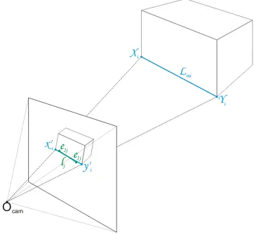
The mathematical model is formulated using homogeneous rep-resentation of the image and model features. The condition for coplanarity of building corners defining an edge and a line seg-ment in the image is utilized for this purpose (Fig. 1). In ad-dition to the functional model, the stochastic model is also de-fined in order to take the uncertainty of the 3D model and image features into account. The covariance matrices of the homoge-neous entities are often singular. To be able to cope with such co-variance matrices, additional constrains for the observations are needed. Optimal exterior orientation parameters are estimated using Gauss-Helmert model.
Figure 1: Principle of assignment of image line segments to 3D model edges
3.1 Finding correspondences
In the presented approach, line segments are selected to be used for matching. The corresponding image line segments are as-signed to the model edges using an accumulator approach. The model edges are projected into the image using the initial exte-rior orientation taken from the navigation device and moved and rotated in the image creating a 3D accumulator space. For each position of the projected model in the image, the number of fitting lines segments in the image is counted. Correspondences which voted for the accumulator cell with most line correspondences are used for the optimal pose estimation.
3.2 Optimal camera pose estimation
Estimation of the exterior orientation parameters in the projec-tive space is formulated using the complanarity of
l
j,X1
i andX2
i, whereX1
i andX2
i are the endpoints of a building edgecorresponding to line segment
l
j detected in the image.Copla-narity of
l
j,X
1i andX
2i is expressed as incidence of thepro-jected points
x
′1iand
x
′2iwith the linel
j. The projected pointsx
′1i:x′1i=PX1iand
x
′2i:x′2i=PX2i, wherePis thepro-jection matrix. Then, the incidence conditionslTjx′1i = 0and
lTjx′2i= 0write
lTjPX1i= 0, (1)
lTjPX2i= 0. (2)
These two equations are directly adapted in the Gauss-Helmert model as conditions
g1(βb,by) =lTjPX1i, (3)
g2(βb,by) =lTjPX2i (4)
for the observations and parameters.
Also in the projective space the uncertainty of the image features and 3D building model can be introduced. The covariance ma-trix for a 3D point
X
represented in homogeneous coordinatesX can be directly derived from the cavariance matrixΣX X for theEuclidean representationXof this point as
ΣXX=
However, due to redundancy in the homogeneous representation, the cavarinace matrix ΣXX is singular (F¨orstner, 2004) which
leads to restrictions in the optimization. To solve this problem, all entities has to be spherically normalized (Kanatani, 1996), so thatlsj = Ns(lj)1,Xs1i = Ns(X1i)andYs1i = Ns(Y1i). (In the rest of this Section, the indexsis omitted assuming the homoge-neous coordinates to be spherically normalized.) This normaliza-tion has to hold also during the estimanormaliza-tion. Therefore, also the constrains
c1(by) =kljk −1 (6)
c2(by) =kX1ik −1 (7)
c3(by) =kX2ik −1 (8)
for the observations are needed.
To find optimal solution for the unknown parameters
b
β= [Xb0,Yb0,Zb0,ωb,φb,bκ], the optimization method for homoge-neous entities presented in (Meidow et al., 2009a) and (Meidow et al., 2009b) is adapted for this functional model. For this pur-pose, the Lagrange function
is minimized, whereλandνare the Lagrangian vectors. In con-trast to (Meidow et al., 2009a) and (Meidow et al., 2009b), here the restriction for the estimated parameters h1(bβ) = 0is not needed, because the estimated parameters are defined directly as exterior orientation parameters X0, Y0, Z0, ω, φ, κ. The observation vector for each pair of corresponding lines writes yij = [lj,X1i,X2i]T, wherel = [a,b,c]T is the homogeneous representation for the image line segment andX1i,X2iis the
ho-mogeneous representation of the corners of the corresponding 3D building edge. The covariance matrixΣllis assumed to be known
as result of the line fitting or as result of error propagation know-ing the covariance matrices of the end points of the detected line segment. This done using 1The covariance matrixΣ
llcalculated as shown in eq. 10 is not
whereSis the skew-symmetric matrix
The solution for the unknown parameters fulfilling eq. 9 is cal-culated in a iterative manner, similar as described in (Meidow et al., 2009b). For all conditions the Jacobians are calculated at the approximate values ofβas
A=
and used for normal equation
ATBΣllBT The indexτdenotes the current iteration. Then the residuals are computed as
Switching from the Euclidean to the homogeneous representa-tion for point
x
in 2D orX
in 3D is usually effected by adding1as an additional coordinate (homogeneous part). Hence, for a 2D point in Euclidean spacex = [u,v]T, the equivalent homo-geneous representation isx = [u,v, 1]T, and for a 3D point in
Euclidean spaceX= [U,V,W]T, the equivalent homogeneous
representation isX= [U,V,W, 1]T. In many photogrammetric
applications, particularly in aerial photogrammetry, the points are given in geodetic coordinate systems (e.g., Gauss-Kr¨uger, UTM), where the values forUandV is in order106. Computations with such inconsistent number can lead to numerical instability of the computations. To solve this problem, the homogeneous entities should be conditioned. Similar to the conditioning proposed by (Heuel, 2002), also here, the entities are conditioned before opti-mizing, by checking the condition
maxhO= maxi
wherexhi is the homogeneous andxOi the Euclidean part of
a homogeneous entityxi. IfmaxhO < fminthe conditioning
factor is calculated as
f=maxh0·fmin (20)
In case of very large Euclidean partxO compared to the
homo-geneous partxh,fcalculated as shown in eq. 20 can be smaller
than the machine accuracyǫh. Hence, iff < ǫhthenfshould
be calculated as
f= fmin
maxi(kxOik)
(21)
((Heuel, 2002)). Next, each entity is conditioned using matrices
Wx(f) =
for the 2D lines and
WX(f) =
so that the conditioned coordinatesxc,lcandXcare calculated as
xc=Wx(fim)x, (25)
lc =Wl(fim)l (26)
and
Xc=WX(fmod)X, (27) wherefimis the conditioning factor for the 2D image entities
andfmodis the conditioning factor for the 3D entities.
Condi-tioning entities changes also the transformation matrix. Here the transformation matrix is the projection matrixPwhich can be reconditioned using
P=W(fim)−1PcW(fmod). (28)
4. IDENTIFICATION OF ERRORS IN THE MODEL
The inaccuracies in the model should result in large residuals in the adjustment. This can be used to identify these inaccura-cies. For this purpose, an outlier detector using statistical test on corrections to the observations is implemented within the adjust-ment. This is done by using weight matrix
b
P =BΣllBT −1
(29)
for computation of the weight coefficient matrix for the correc-tions to observacorrec-tions
Qvbvb=
QBTPbI−A(ATP Ab )−1ATPbBQ (30)
Then the vector of standardized corrections for the observations is calculated.
V = |(y−y0)| σ0pdiag(Qvbvb)
(31)
Statistical tests are used to identify the outliers using the critical value
ǫh=χ21−α,1, (32)
which allows rejecting a hypothesis with the significance levelα. IfVi> ǫhthen this observation is considered as an outleir.
estima-tion and the link to the corresponding model edges is stored. Then the procedure is repeated for every frame of the image sequence. Model edges which are frequently identified as outlieres are la-beled as possible errors in the 3D model.
5. RESULTS
The results are presented on an oblique thermal infrared (TIR) image sequence taken from helicopter flying over a densely built up urban area. The frame rate was 25 frames/sec. which gives a high overlap between the frames. 100 following frames (with frame IDs 13141-13240) and three buildings were selected for the first tests. The 3D building model was created manually in a commercial software by fitting predefined building primitives. Hence, no roof overhang is modeled. The significance level was set toα= 0.1for the experiments.
Each observation is represented by 11 parameters, 3 related to the image line, and 8 related to model corners. In the presented method, each parameter is treated separately. It means that for each observation, one or more parameters can be identified as an outlier. It can be also distinguish between outliers in the image feature and outliers in the 3D building model. However, the usage of this fact is not sufficient for outlier detection in the 3D model, because the inaccuracies in the line detection can also affect the errors in the parameters of the model points. Tests showed that both errors coexist. Outliers in the line parameters were detected in less cases and in most cases they were coexisting with a errors in the parameters of model points. The outliers in image line parameters were detected for 151 edges in 100 frames but only in 21 cases they did not coexist with outliers in the parameters of model points.
Figure 2: Results on outlier detection in the frame no. 13209: a) outliers detected based on analysis of parameters of model points; b) outliers detected based on analysis of parameters of im-age lines; c) outliers detected based on analysis of all parameters. Color coding: dark cyan - detected image line segments with-out correspondences, bright cyan - projected model edges withwith-out correspondences, dark green - detected image line segments with correspondences, bright green - projected model edges with cor-respondences, dark orange - detected image line segments with correspondences detected as outliers, bright green - projected model edges with correspondences detected as outliers
Fig. 2 shows results on the outlier detection in an exemplary frame. Here, all three possibilities are presented, taking the out-liers in the image line parameters, model point parameters or both
at the same time. For the outliers removal and outlier free adjut-ment the third option was used. The results of the adjustadjut-ment after outlier removal are presented in Fig. 3
Figure 3: Projected 3D building model in frame 13209 before (red) and after (green) adjustment
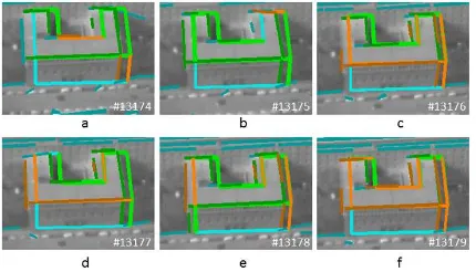
Fig. 4 shows the results of outliers detection using all parameters for each observation. The results are shown on one exemplary building and across a sub-sequence of 6 following images.
Figure 4: Outlier detection for one building across a sub-sequence of 6 images (13174-13179). Color coding: same as Fig. 2
6. CONCLUSION
In this paper we presented a method for model-to-image match-ing with optimal pose estimation and outlier detection withmatch-ing the estimation. The novelty of the presented methodology con-sist of the usage of the linear features and their uncertainty in the adjustment process which allows for more reliable outlier detec-tion. Using the implemented method, buildings or building parts being potentially badly modeled can be identified. However, this identification is useful only for further manual post-processing. In the future, more work should be done on more automatic con-firmation of an error in the building and automatic improvement of the geometry.
ACKNOWLEDGEMENTS
The authors would like to thank Frauenhofer IOSB, Ettlingen, for providing thermal images.
REFERENCES
Borrmann, D., Elseberg, J. and N¨uchter, A., 2012. Thermal 3d mapping of building fac¸ades. In: Proceedings of the 8th Confer-ence on Intelligent Autonomous Systems. Jeju Island, Korea.
Chandler, D., 2011. The big picture on energy loss. MIT news. Access on July 30, 2012.
Groneman, A., 2004. Toposcopy combines photogrammetric modelling with automatic texture mapping. In: The Interna-tional Archives of Photogrammetry, Remote Sensing and Spatial Geoinformation Sciences. Proceedings of the ISPRS workshop on Vision techniques applied to the Rehabilitation of City Cen-tres held in Lisbon, Portugal.
Hebel, M. and Stilla, U., 2011. Simultaneous calibration of als systems and alignment of multiview lidar scans of urban areas. IEEE Transactions on Geoscience and Remote Sensing 50(6), pp. 2364–2379.
Hegarty, J. and Carswell, J., 2009. Samats - texture extraction ex-plained. In: The International Archives of Photogrammetry, Re-mote Sensing and Spatial Geoinformation Sciences, Vol. 38num-ber 5/W1.
Heuel, S., 2002. Statistical Reasoning in Uncertain Projective Geometry for Polyhedral Object Reconstruction. PhD thesis, Photogrammetry Department, Institute for Geodesy and Geoin-formation, Bonn University, Germany, Nussallee 15, 53115 Bonn, Germany.
Hoegner, L., Kumke, H., Meng, L. and Stilla, U., 2007. Auto-matic extraction of textures from infrared image sequences and database integration for 3d building models. PFG Photogramme-trie Fernerkundung Geoinformation 2007(6), pp. 459–468.
Huertas, A. and Nevatla, R., 1998. Detecting changes in aerial views of man-made structures. In: Computer Vision, 1998. Sixth International Conference on, pp. 73–80.
Iwaszczuk, D., Helmholz, P., Belton, D. and Stilla, U., 2013. Model-to-image registration and automatic texture mapping us-ing a video sequence taken by a mini uav. In: Proceedus-ings of ISPRS Hannover Workshop 2013.
Iwaszczuk, D., Hoegner, L. and Stilla, U., 2011. Matching of 3d building models with ir images for texture extraction. In: U. Stilla, P. Gamba, C. Juergens and D. Maktav (eds), Proceed-ings of JURSE 2011 - Joint Urban Remote Sensing Event, pp. 25– 28.
Iwaszczuk, D., Hoegner, L., Schmitt, M. and Stilla, U., 2012. Line based matching of uncertain 3d building models with ir im-age sequences for precise texture extraction. Photogrammetrie, Fernerkundung, Geoinformation (PFG) 2012(5), pp. 511–521.
Kanatani, K., 1996. Statistical optimization for geometric com-putation : theory and practice. Machine intelligence and pattern recognition, Elsevier, Amsterdam, Lausanne, New York.
Meidow, J., Beder, C. and F¨orstner, W., 2009a. Reasoning with uncertain points, straight lines, and straight line segments in 2d. ISPRS Journal of Photogrammetry and Remote Sensing 64(2), pp. 125–139.
Meidow, J., F¨orstner, W. and Beder, C., 2009b. Optimal pa-rameter estimation with homogeneous entities and arbitrary con-straints. In: J. Denzler and G. Notni (eds), Pattern Recognition (Symposium of DAGM), Springer, pp. 292–301.
Nyaruhuma, A. P., Gerke, M. and Vosselman, G., 2012. Veri-fication of 3d building models using mutual information in air-borne oblique images. In: ISPRS Annals of the Photogrammetry, Remote Sensing and Spatial Information Sciences, XXII ISPRS Congress, 25 August 01 September 2012, Melbourne, Australia, Vol. I-3.