Polymer Solar Cells: Effects of Annealing Treatment and
methoxy-5-(3,7-dimethyloctyloxy)-para phenylene vinylene)] (MDMO-PPV) and the soluble fullerene C60 derivative [6,6 phenyl C61-butyric acid methyl ester] (PCBM). These polymers act as an active layer for bulk heterojunction photovoltaic devices. The device was fabricated on an indium tin oxide (ITO) coated glass substrate with a sheet resistance 8-12 Ω/s ua e. Afte cleaned and dried the substrate, a poly(3,4-ethylenedioxythiophene):poly(styrenesulfonate) (PEDOT:PSS) in H2O was spin coated onto the freshly prepared substrate using an adhesivetape mask. The mask was then removed, and the substrate was dried in a vacuum oven at 120ºC for 60 minutes. The device and then masked again and a blend of MDMO-PPV and PCBM in chorobenzene was then spun coated on top. The mask was removed and transferred to an evaporator where an aluminum was coated through a shadow mask to define an active device area of 2,6 cm2. Some of the devices then
annealing in a vacuum oven at 60ºC for 60 minutes. The sealant was placed between the back of the device and a glass slide, and then cured in an oven with a temperature of 100 ºC for 10 minutes in vacuum condition. For characterization, the device was illuminated with a mercury lamp at the intensity of 27 mW/cm2 and the temperature approximately 25ºC. The influence of the annealing treatment and polymer blends
on the photovoltaic performance of the device is observed here. The best performance was obtained from the device with a blend ratio of 1:1 MDMO-PPV/PCBM without annealing treatment. The typical power efficiency was 0.001 % with open circuit voltage of 0.347 V, short circuit current of 0.064 mA, and maximum power of 0.006 mW.
Keywords: Annealing, Blends, Bulk heterojunction, Polymer, Solar cells.
1. Introduction.
The discovery of photo induced charge transfer in composites of conjugated polymer and fullerene initiated a strong research effort toward exploitation of this process as an efficient charge-generation step in organic photovoltaic devices with the aim of fabricating low-cost solar cells [1]. The large exiton-binding energy in a polymeric matrix result in strongly localized electron hole-pairs upon light absorption, giving rise to the small exciton-diffusion length and inefficient exciton dissociation [2]. Photovoltaic cells made from single organic semiconductors therefore achieve tiny power conversion efficiencies and low incident-photon-to-current or external quantum efficiencies (EQE) [3]. A solution was only found in 1995, when several groups independently showed that the EQE could be enhanced by several orders of magnitude upon blending two materials with relative preferences for positive and negative charges resulting in a device architecture often referred to as the bulk heterojunction. The difference in electron affinities creates a driving force at the interface between the two materials that is strong enough to split photo generated exciton. By blending materials on a nanostructured scale (about 10 nm), the interface is distributed throughout the device [3].
is used on the illumination side, and evaporated thin (80–100 nm) lithium fluoride/aluminum metal contact matching the LUMO of PCBM (electron contact) is used on the other side. In the state-of-the-art devices, a thin (100 nm) hole-injection layer, a highly doped PEDOT-PPS film is used, which also serves to smoothen the surface of the ITO and to increase device stability. The maximum open circuit voltage of a MDMO-PPV: PCBM device is ~0.8 V at room temperature, which corresponds to the energy level difference between the LUMO of PCBM, and the HOMO of MDMO-PPV. Moreover, it was observed that the open-circuit voltage was only a very weak function of the work function of the cathode material used, but strongly depends on the LUMO of the electron acceptor used
[4].
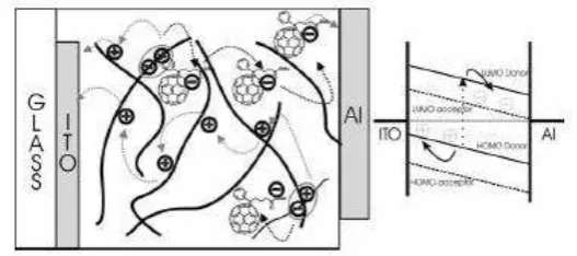
Figure 1. Schematic illustration of a bulk heterojunction based on the interpenetrating network of a conjugated polymer and PCBM. Charge carriers generated by photo-induced electron transfer are moving towards the corresponding electrode. The
electronic levels relevant to the device operation are also displayed [4].
Figure 2. Chemical structures of materials used in plastic solar cells: MDMO-PPV poly[2-methoxy-5-(3,7-dimethyloctyloxy)-phenylene vinylene], P3HT (poly(3-hexylthiophene-2,5-diyl),PCBM1-(3-methoxycarbonyl)propyl-1-phenyl-(6,6)-C61, and PTPTB
(poly-N-dodecyl-2,5,-bis(2′-thienyl)pyrrole,2,1,3-benzothiadiazole [4].
2. Materials and Methods.
The structure of the bulk heterojunction solar cell is shown in figure 3. The substrate was used is ITO covered glass slide (Aldrich) in 25 mm × 25 mm × 1.1 mm dimension with a thickness of 120 nm and a sheet resistance of
Ω/□. The ITO were masked using a positive photoresist (the mask pattern was shown in figure 4), exposing the part of the ITO that should be etched. The substrate was then etched using an aqueous solution of HCl/HNO3/H2O at a temperature of 60 ºC for 120 seconds and then cleaned by ultrasonication in water, aceton and isopropanol for 15 minutes, respectively, before dried in N2.
Figure 3. Schematic diagram of the device structure of the bulk heterojunction solar cell connected to an external load.
Figure 4. The mask patterns of ITO, PEDOT:PSS, active layer, and aluminum.
Prior employed the active layer, the PEDOT:PSS in H2O (Aldrich) was spin-coated onto the freshly prepared substrate at 2800 rpm for 30s using an adhesive tape mask. After removal of the mask, the substrate was dried in a vacuum oven at 120ºC for 60 minutes. The device and then masked again and a solution of MDMO-PPV and PCBM (1:1 wt/wt) and (1:4 wt/wt) in chorobenzene, respectively, was then spin-coated on top. The mask was removed, and the substrate was transferred to a sputtering where the aluminum was coating.
For the cathode, a 134 nm thick film of aluminum was sputtered onto the active layer through a shadow mask to define an active device area of 2,6 cm2. The sputter parameter was 75 Watts in dc power for 10 minutes. Some of the devices then annealing in a vacuum oven at 60ºC for 60 minutes.
Glass slide in 20 mm x 20 mm dimensions were employed to match the sealing area of the back of the photovoltaic device. The sealant (Dyesol) was placed between the device and the glass slide and cured in an oven with a temperature of 100 ºC for 10 minutes in vacuum condition. The device as shown in figure 5 was ready for electric characterization. The I-V characteristics for the device were obtained using a solar simulator with a xenon lamp (AM 1.5 filtered) . The incident light intensity was approximately 270 W/m2, and the temperature was 25ºC. Electrical measurements were performed using a I-V Measurement from National Instrument. The surface of the active layer before and after annealing treatment were investigated using atomic force microscopy (AFM).
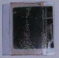
Figure 5. The polymer solar cell's device prototype.
3. Results and Discussion.
Figure 6 shows the current density vs voltage (I-V) characteristics under a solar simulator with an intensity of 27 mW/cm2. The electric characteristics are shown in Table 1. The devices without annealing treatment (casting) show high performance with open circuit voltage Voc = 0.347 V, short circuit current Isc= 0.064 mA, fill factor FF = 0.280, and Voc = 0.184 V, Isc= 0.072 mA, FF = 0.515 for blend ratio of 1:1 and 1:4, respectively. The power conve sion efficiency η fo these devices are similar, η = 0.01%, and η = 0.01. The devices with annealing treatmentat 60 ºC for 60 minutes exhibit poor performance compared to that of without annealing. The Voc, Isc, and FF both decrease into 0.041 V, 0.065 mA, 0.293 and 0.102 V, 0.075 mA, and 0.235 for blend ratio of 1:1 and 1:4, respectively. The corresponding power conversion efficiencies are therefore, only η= 0.001 %, and η= 0.003 %. The decrease in power conversion efficiency is mainly caused by a significant decrease in Voc. This result is in agreement with previous publications on the effects of thermal annealing of MDMO-PPV/PCBM polymer blends. They reported that a sudden drop in efficiency after annealing for only a few seconds at 130 ºC or a few minutes at 75 ºC and 80 ºC [5,6,7].The origin of this instability was degradation of the morphology resulted from the formation of large PCBM aggregates [7,8].
Figure 6. I-V characteristics of MDMO-PPV/PCBM polymer solar cells.
Table 1. Electrical Characteristics of MDMO-PPV/PCBM polymer solar cells.
No. Characteristics 1:1 MDMO-PPV/PCBM, while the FF and Isc are lower. This indicates that the higher PCBM ratio is strongly contributed to the degradation of the Voc, but on the other hand, it also increases the FF and Isc. Therefore, to increase the efficiency; it is necessary to optimize the ratio between MDMO-PPV and PCBM blends.
sputtered Al as a cathode layer, where sputtering process can result in damage to organic solar cell absorber (active) layer as a result of the bombardment of highly energetic particles such as reflected argon ions or scattered electrons [9]. The low in fill factor implies high series resistance and low carrier mobility, which is caused the effect of impurities, such as oxygen, which act as traps to the migrating excitons [10]. Another factor which also decreases I-V characteristic is wider active area and the temperature of sealing.
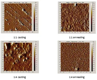
Atomic force microscopy (AFM) images of the MDMO-PPV/PCBM surface films before and after annealing treatment, are shown in Figure 7.
1:1 casting 1:1 annealing
1:4 casting 1:4 annealing
Figure 7. AFM images of MDMO-PPV/PCBM films in polymer solar cells.
4. Conclusions.
Polymer solar cells based on blends of [poly(2-methoxy-5-(3,7-dimethyloctyloxy)-para phenylene vinylene)] (MDMO-PPV) and [6,6 phenyl C61-butyric acid methyl ester] (PCBM) has been prepared on a glass substrate. The best performance was obtained from the device with a blend ratio of 1:1 MDMO-PPV/PCBM without annealing treatment. The typical power efficiency was 0.0094 % with open circuit voltage of 0.1839 V, short circuit current of 0.0716 mA, and maximum power of 0.068 mW.
Acknowledgement
This work is supported by DIPA Programme of PPET-LIPI 2011-2013.
References
[1] S.C. Veenstra, W.J.H. Verhees, J.M. Kroon, M.M. Koetse, J. Sweelssen, J.J.A.M. Bastiaansen, H.F.M. Schoo, X. Yang, A. Alexeev, J. Loos, U.S. Schubert, and M.M. Wienk. 2004. Photovoltaic properties of a Conjugated Polymer Blend of MDMO-PPV and PCNEPV. Chemistry of Materials, 16 : 2503-2508.
[2] Li Min Chen, Ziruo Hong, Gong Li, and Yang Yang. 2009. Recent Progress in Polymer Solar Cells: Manipulation Polymer: Fullerene Morphology and the Formation of Efficient Inverted Polymer Solar Cells. Advanced Materials, 21 : 1434-1449. [3] C.J. Brabec. 2004. Organic photovoltaics:technology and market. Solar Energy Materials & Solar Cells, 83 : 273–292. [4] Attila J. Mozer and Niyazi S. Sariciftci. 2006. Conjugated polymer photovoltaic devices and materials. Comptes Rendus
Chimie, 9 : 568–577.
[5] Xiaoniu Yang and Joachim Loos. 2007. Toward High-Performance Polymer Solar Cells: The Importance of Morphology Control. Macromolecules , 40 (5) : 1353-1362.
[6] F. Padinger, R.S. Rittberger, and N.S. Sariciftci. 2003. Effects of Postproduction Treatment on Plastic Solar Cells. Advanced Functional Materials, 13: 85-88.
[7] D. Chirvase, J. Parisi, J.C. Hummelen and V. Dyakonov. 2004. Influence of nanomorphology on the photovoltaic action of polymer–fullerene composites. Nanotechnology, 15 : 13-17.
[8] H. Hoppe, M. Niggemann, C. Winder, J. Kraut, R. Hiesgen, A. Hinsch, D. Meissner, and N.S. Sariciftci. 2004. Nanoscale Morphology of Conjugated Polymer/Fullerene-Based Bulk-Heterojunction Solar Cells. Advanced Functional Materials, 14 : 1005-1011.
[9] E. Ahlswede, J. Hanisch, and M. Powalla. 2007. Influence of cathode sputter deposition on organic solar cells. Applied Physics Letters, 90 :063513, 1-3.
[10] G.G. Wallace, P.C. Dastoor, D.L. Officer, and C.O. Too. 2000. Conjugated polymers: New materials for photovoltaics.
Chemical Innovation, 30 (1) : 14–22.