SYNTHESIS OF MULTILEVEL AND BINARY SEQUENCES WITH GOOD CORRELATION
PROPERTIES
SITI JULIA ROSLI
UNIVERSITI MALAYSIA PERLIS MALAYSIA
2013
© This
item is protecte d by
original
copyr
ight
SYNTHESIS OF MULTILEVEL AND BINARY SEQUENCES WITH GOOD CORRELATION
PROPERTIES
by
SITI JULIA ROSLI 1130210577
A thesis submitted
In fulfillment of the requirements for the degree of Master of Science (Computer Engineering)
School of Computer and Communication Engineering UNIVERSITI MALAYSIA PERLIS
MALAYSIA 2013
© This
item is protecte d by
original
copyr
ight
i
UNIVERSITY MALAYSIA PERLIS
DECLARATION OF THESIS
Author‟s full name : SITI JULIA ROSLI Date of birth : 27/07/1984
Title : SYNTHESIS OF MULTILEVEL AND BINARY SEQUENCES WITH
GOOD CORRELATION PROPERTIES Academic Session : 2011 / 2012
I, hereby declare that this thesis becomes the property of University Malaysia Perlis (UniMAP) and to be place at the University library. This thesis is classified as :
CONFIDENTIAL (Contains confidential information under the Official Secret Act 1972) RESTRICTED (Contains restricted information as specified by the organization where
research was done)*
OPEN ACCESS I agree that my thesis is to be made immediately available as hard copy or on-line open access (full text)
I, the author, give permission to the UniMAP to reproduce this thesisin whole or in part of the purpose of research or academic exchange only (except during a period of……. years, if so requested above).
Certified by:
_____________________ _____________________
SIGNATURE SIGNATURE OF SUPERVISOR
840727-07-5364 Professor. Farid Ghani
(NEW I/C NO./PASSPORT NO.) NAME OF SUPERVISOR
Date:_________________ Date: _________________
NOTES: * If the thesis is CONFIDENTIAL or RESTRICTED, please attach with the letter from the organigation with period and reasons for confidentially or restriction.
© This
item is protecte d by
original
copyr
ight
ii
ACKNOWLEDGEMENTS
Firstly, I would like to express my deepest gratitude to my supervisor, Prof. Farid Ghani, for his guidance and support throughout the course of my research. He has been more than helpful in creating opportunities for priceless learning experience during his supervision. I also admire his patience with my pace of work. I also would like to sincerely thank Mr. Alif Hasmani Abd Ghani for additional advice and help. Without his patience, guidance and constant supports, this work would not have been possible.
Secondly, my sincere thanks go to Ms. Sofia, Ms. Shazwani and Mr. Zulkefli for their generous help and technical support offered during my laboratory work. Their patience when working with me during my experiments is truly appreciated as my work can be very repetitive and unexciting from others point of view. I would also like to thank my research colleagues, especially Ms. Normaliza, Mrs. Aznor, Mrs. Aini and my entire colleague especially in MCRG lab for their assistance in research, ingenious ideas during discussion and lasting friendship together.
Last but most importantly, I wish to acknowledge the care and encouragement given by my lovely son, husband, parents and my siblings. Thank you very much for supporting me in so many ways from the beginning until the end.
Siti Julia Rosli
Universiti Malaysia Perlis (UniMAP) [email protected]
© This
item is protecte d by
original
copyr
ight
iii
TABLE OF CONTENTS
PAGE
DECLARATION OF THESIS………i
ACKNOWLEDGEMENTS………ii
TABLE OF CONTENTS………iii
LIST OF TABLES………..viii
LIST OF FIGURES………x
LIST OF ABBREVIATIONS………xiii
ABSTRAK………...xiv
ABSTRACT………xv
CHAPTER 1: INTRODUCTION 1.1 Background Project……….1
1.2 Basic Concept of Radar Waveform……….5
1.3 Problem Statement………..7
1.4 Research Objectives………8
1.5 Scope of Project………..9
1.2 Outline of Thesis……….9
CHAPTER 2: BASIC SIGNAL PROCESSING CONCEPTS IN WAVEFORM DESIGN 2.1 Introduction………....11
2.2 Representation of Pulse Train………11
2.2.1 Complex Envelope and Band-pass Filtering………..11
© This
item is protecte d by
original
copyr
ight
iv
2.2.2 The Z-Transform………15
2.2.2.1 Definition of the z-Transform……….15
2.2.2.2 The z-Transform and Linear Systems……….16
2.2.2.3 Properties of the z-Transform……….17
2.2.2.4 A General z-Transform Formula………....17
2.2.2.5 The z-Plane and the Unit Circle………..18
2.3 Optimum Processing of Radar Signals……….19
2.3.1 Digital Matched Filters………..19
2.3.2 Pulse Compression Radar………..20
2.3.3 Range Resolution in M.F Radar………....22
2.4 Summary………..24
CHAPTER 3: LITERATURE REVIEW 3.1 Introduction……….25
3.2 Research Methodology………...26
3.3 Amplitude and Phase Modulated Sequences………..28
3.4 Phase Modulated Sequence……….30
3.5 Summary………..33
CHAPTER 4: DESIGN OF AMPLITUDE AND PHASE MODULATED PULSE TRAINS 4.1 Introduction………...35
4.2 Iterative Process for the Generation of Multilevel Sequences………..36
4.2.1 Introduction………...36
© This
item is protecte d by
original
copyr
ight
v
4.2.2 Basic of Optimum Inverse (Least Error Energy) Filter………….36
4.2.3 Autocorrelation Function (ACF) of the Filter Coefficient……….40
4.2.4 Iterative Generation of Multilevel Sequences (Method M1)…….41
4.2.5 Results and Discussion ………..42
4.5 Choice of Starting Sequence………..46
4.5.1 Choice at Random………..46
4.5.1.1 Designing Multilevel Sequences Using m integer and N Length………..47
4.5.1.2 Zeros Pattern………..49
4.5.2 Effect of Optimum Pulse Position………54
4.5.3 Conditions for Convergence……….56
4.6 Averaging the Inverse Filter Coefficients with Input Sequence…………..57
4.7 Summary………..58
CHAPTER 5: DESIGN OF BINARY CODED PULSE TRAINS 5.1 Introduction and Methodology………..60
5.2 The Optimization Problem……….61
5.2.1 Formulation of the Synthesis Problem………61
5.2.2 Synthesis Using Element Complementation………..61
5.2.2.1 Sign or Magnitude Notation……….63
5.2.2.2 Results and Discussion……….63
5.2.3 Synthesis Using Cyclic Shift and Bit Addition………...65
5.2.3.1 Cyclic Shift (Mutation method)………...65
5.2.3.2 Bit Addition………...66
© This
item is protecte d by
original
copyr
ight
vi
5.2.3.3 Results and Discussion……….67
5.3 Clipping of Multilevel Sequences………..71
5.3.1 Introduction……….71
5.3.2 Results and Discussion………...72
5.4 Summary……….77
CHAPTER 6: SYNTHESIS OF BINARY AND MULTILEVEL SEQUENCES OF HIGHER LENGTHS 6.1 Introduction and Methodology………..84
6.2 The Proposed Method………85
6.3 Choice of Starting Sequence………...86
6.3.1 Binary Sequence as Starting Sequence………..87
6.3.2 Multilevel Sequence as Starting Sequence……….88
6.3.3 Results and Discussion………...89
6.4 Choice of Step Size………92
6.4.1 Introduction……….92
6.4.2 Results and Discussion………...93
6.4.2.1 Clipping of Multilevel Sequences………...95
6.4.2.2 Discussions………..98
6.5 Summary………...99
CHAPTER 7: CONCLUSION AND FUTURE WORKS 7.1 Conclusion………105
7.2 Future Works………107
© This
item is protecte d by
original
copyr
ight
vii
REFERENCES……….108 APPENDIX………115 LIST OF PUBLICATIONS……….144
© This
item is protecte d by
original
copyr
ight
viii
LIST OF TABLES
NO. PAGE
Table 2.1 Advantages and disadvantages of the pulse compression 22
Table 3.1 Barker Sequences 32
Table 4.1 Sequences of computer runs from Optimum Inverse Filter Method by iterative Process
44 Table 4.2 Sequences Generated By Integer Values of m 49 Table 4.3 Rectangular coordinates and polar coordinates from original and
editing/adding pole
53 Table 4.4 Correlation Values Obtained within input sequences of length 13
(Hx)
55 Table 4.5 Correlation Values Obtained within input sequences of length 13
(Hb)
56
Table 4.6 Comparison Results Between Literature and M1 Method. 59 Table 5.2 Listing of the possibility sequences of length thirteen 63 Table 5.3 Listing of the possibility sequences of length-15 64 Table 5.4 The possibility sequences of length-17 64 Table 5.5 The Generated Sequences for Cyclic Shift method 69 Table 5.6 The Generated Sequences for Bit Addition Method with two
complement number
69 Table 5.7 THREE Set of Sequences Obtained Using Mutated Process 70 Table 5.8 The Generated Clipping Sequence by percentage of clipping
level
76 Table 5.9 Values of the various methods (B2, B4, B5, B6 and B7) from the
iterated process
78 Table 6.1 Values of M2 method from the iterated process 90
© This
item is protecte d by
original
copyr
ight
ix
Table 6.2 Values of M3 method from the iterated process 90 Table 6.3 Values of M4 method from the iterated process 91 Table 6.4 Values of M5 method from the iterated process 91 Table 6.5 Values of the various methods (M2, M3, M4, and M5) from the
iterated process
99
© This
item is protecte d by
original
copyr
ight
x
LIST OF FIGURES
NO. PAGE
Figure 1.1 Basic Radar System 6
Figure 2.1 Bandpass communication system 12
Figure 2.2 (a) Bandpass signal (b) Complex envelope 14
Figure 2.3 w-domain vs z-domain 18
Figure 2.4 z-Plane 18
Figure 2.5 Matched Filter 19
Figure 2.6 Separation of frequency modulated pulses 21
Figure 2.7 One target includes two aims (a) Two aims with too small spacing (b) Two aims when the spacing is large enough 23
Figure 3.1 Flowchart showing the Methodology for the Generation of Multilevel and Binary Sequences using the Iterative Method 26
Figure 3.2 (a) Barker code of length 13, a long pulse width 13 equal subdivions whose individual phases are either ( ) ( ).(b) Autocorrelation of (a), which represents the output of the matched filter 32
Figure 3.3 Ambiguity Function of a 11-chip Barker Coded Waveform 34
Figure 3.4 Example of binary phase shift keying using one cycle per bit 34
Figure 4.1 The optimum inverse filter problem 37
Figure 4.2 Optimum Inverse Filter flowchart 41
Figure 4.3 Program for taps gain of the optimum inverse filter 42
Figure 4.4 Program for normalizing the filter tap gains and calculate the sum of tap gains 42
Figure 4.5 Variation in Sidelobe Energy and Energy Ratio with Computer 46
© This
item is protecte d by
original
copyr
ight
xi Runs for 13-Element Barker sequence
Figure 4.6 Flow chart of code plot coordinates with adding/editing zeros 52 Figure 4.7 Zeros pattern for length-13 and integer m=1 53 Figure 4.8 Complex Envelope of the Pulse Trains from the Original and
editing Zeros pattern
54 Figure 4.9 Autocorrelation Function of the Original Sequences (Hx) 55 Figure 4.10 Autocorrelation Function of the Generated Sequences (Hb) 56 Figure 4.11 Graph plotting for Huffman Sequences and Multilevel Sequences
that good in ACF
57
Figure 5.1 Complementation Method flowchart 62
Figure 5.2 Sidelobe Energy versus Length of Sequences for 13 until 21 lengths using the Synthesis of Element Complementation
65 Figure 5.3 Example the sum of the bit integers 66 Figure 5.4 Cyclic Shift and Bit Addition flowchart 68 Figure 5.5 Side Lobe Energy of the generated sequences (Table 5.6) when
applying the Mutation Method
70
Figure 5.6 Algorithm for Clipping Method 74
Figure 5.7 Flow chart for Clipping Methods program 75 Figure 5.8 Clipping Levels of Huffman Pulses 76 Figure 5.9 Side Lobe Energy and Energy Ratio at different clipping levels
for Huffman sequences of length-13
77 Figure 6.1 Flow chart showing the generation of multilevel sequences using
inverse filter. The length of the generated sequence is same as that of the starting multilevel sequence
86
Figure 6.2 Binary Sequence as Starting and Input Sequence(a) Binary Sequence as Input Sequence (b)Multilevel Sequence as Input Sequence
88
Figure 6.3 Multilevel Sequence as Starting Sequence and (a) Binary Sequence as Input Sequence; (b)Multilevel Sequence as Input
89
© This
item is protecte d by
original
copyr
ight
xii Sequence
Figure 6.4 Sidelobe Energy ofM2, M3, M4 and M5 Method for various length
92 Figure 6.5 Flow chart showing the generation of multilevel sequences of
larger lengths using an inverse filter. The length of the generated sequence is greater than that of the starting sequence
93
Figure 6.6 Sidelobe Energy of generated binary sequences for various lengths and values of k using case 1
94 Figure 6.7 Sidelobe Energy of generated multilevel sequences for various
lengths and values of k using case 2
95 Figure 6.8 Variation in Energy Ratio with clipping percentage for a
sequences of length 21 obtained for k=2, 4, and 8. (a) case 1 (b) case 2
97
Figure 6.9 Sidelobe energy and energy ratio for various levels of clipping a 21-element sequence generated using the proposed method. (a) Case 1 (b) Case 2
97
© This
item is protecte d by
original
copyr
ight
xiii
LIST OF ABBREVIATIONS
3G Third Generation
4G Fourth Generation
AM Amplitude Modulation
ACF Autocorrelation Function
BPSK Binary Phase-Shift Keying
CDMA Code Multiple Access
CW Continuous Wave
DSP Digital Signal Processing
EM Electromagnetic Waves
ER Energy Ratio
FIR Finite impulse response
FDMA Frequency Division Multiple Access
FM Frequency Modulation
ISL Integrated Sidelobe Level
LTI Linear time-invariant
M.F Radar Medium Frequency Radar
MFR Matched Filter Receiver
MFR Matched Filter Receiver
OFDMA Orthogonal Frequency Division Multiple Access
PM Phase Modulation
PSL Peak of Sidelobe Levels
RADAR Radio Detection And Ranging
SLE Sidelobe Energy
SNR Signal to Noise Ratio
© This
item is protecte d by
original
copyr
ight
xiv
Sintesis Urutan Pembilang Aras Dan Urutan Pembilang Perduaan Dengan Sifat Korelasi Yang Baik
ABSTRAK
Dalam sistem radar, cuping sisi yang rendah dicapai dengan mengunakan amplitud dan fasa termodulat terutamanya dalam sistem yang memerlukan julat dinamik yang besar.
Tambahan pula prestasi terbaik dari penolakan „selerakan-diri‟ diperolehi tanpa menjejaskan keupayaan bagi mengasingkan sasaran terdekat (tiada pelebaran lobus utama).
Sebagai tambahan, pengekodan dan penyahkodan dalam amplitud dan fasa termodulat dibenarkan bagi menangani „selerakan-diri‟ atau pengendalian dalam persekitaran sasaran yang padat. Masalah yang telah diberi keutamaan dalam merekabentuk radar adalah memilih penghantar gelombang yang sesuai. Ini kerana gelombang yang mengawal resolusi, prestasi „selerakan‟ dan juga penanggungan kos dari sistem. Suatu kajian teori di mana menyediakan asas untuk kemajuan teknikal dan setakat ini tidak dapat diselesaikan dari aspek rekabentuk isyarat. Secara praktikal, pengetahuan tentang sifat-sifat denyutan nadi menunjukkan isyarat yang sesuai bagi pemprosesan digital semakin dititikberatkan.
Terdapat dua sifat yang ditekankan di dalam urutan tersebut. Pertamanya ialah nisbah tenaga (ER) yang ditakrifkan sebagai nisbah jumlah urutan tenaga kepada nadi tenaga terbesar. Antara sifat lainnya pula adalah jumlah tenaga cuping sisi (SLE) yang mana ia adalah urutan tenaga di dalam cuping sisi fungsi autokorelasi. Penyelidikan yang dijalankan terhadap kajian ini sangat menitikberatkan sintesis bentuk gelombang pembilang aras dan pembilang penduaan bagi urutan panjang mana yang dikehendaki untuk mempunyai peningkatan tenaga nisbah dan penurunan cuping sisi di dalam setiap fungsi autokorelasinya (ACF). Dalam merekabentuk urutan pembilang aras, teknik lelaran adalah dicadangkan. Teknik ini ditugaskan sebagai sifat penapis songsang yang optimum dan ia terbukti berkesan bagi penjanaan urutan panjang pembilang aras yang dikehendaki. Kaedah pengetipan di dalam kajian ini adalah sebagai penukar urutan pembilang aras ke urutan pembilang penduaan dalam panjang urutan yang sama di mana ia masih lagi mengekalkan penurunan cuping sisi di dalam fungsi autokorelasinya. Ini menunjukan bahawa kaedah lelaran berasaskan penapisan songsang dan kaedah pengetipan merupakan kaedah yang berkesan bagi penghasilan urutan pembilang aras yang mempunyai peningkatan nisbah tenaga dan penurunan cuping sisi di dalam setiap fungsi autokorelasinya. Urutan itu kemudian boleh digunakan dengan berkesan untuk meningkatkan julat dan Doppler resolusi radar.
© This
item is protecte d by
original
copyr
ight
xv
Synthesis Of Multilevel And Binary Sequences With Good Correlation Properties
ABSTRACT
In radar systems the very low side lobes that can be achieved with amplitude and phase modulated pulse trains especially particularly in systems requiring a large dynamic range.
Moreover, the excellent self-clutter rejection performance is obtained without sacrificing the ability for the separation of close targets (no main lobe widening). The additional expense of encoding and decoding in amplitude and phase may be justified for radars that must cope with land clutter or operating in a dense-target environment. To choose a suitable transmit waveform is an important problem in radar design. This is so because, the waveform controls resolution, clutter performance and also bears heavily on the system cost. Theoretical studies which provide the basis for technical advances have not so far solved the general signal design problem. The knowledge about the properties of the pulse trains shows that, a class of signals particularly well suited to digital processing of increasing practical importance. Two properties of such sequences are of interest. One is the energy ratio (ER) defined as the ratio of the total energy of the sequence to the energy of the largest pulse. The other property is the total side lobe energy (SLE) which is the energy in the side lobes of the autocorrelation function of the sequency. The work presented in this research is mainly concerned with the synthesis of multilevel and binary waveform of any desired length that has high energy ratio and low side lobe in their autocorrelation function (ACF). For the design of multilevel sequences in iterative technique is proposed, this techniques employed the properties of optimum inverse filtering and shown to be effective for the generation of multilevel sequences in any desired lengths.
The method of clipping proposed in this research converts a multilevel sequence to binary sequence in same lengths while it is still retaining at low side lobe in autocorrelation function. It is shown that the iterative method based on inverse filtering and the method of clipping provide effective techniques for the generation of multilevel sequences that have high energy ratio and low side lobe energy in their autocorrelation function. Such sequences can then be effectively used to improve the range and Doppler resolution of radars.
© This
item is protecte d by
original
copyr
ight
1 CHAPTER 1
INTRODUCTION
1.1 Background of the Project
Radar is a method for remote sensing using radio waves. Its basic purpose is to detect the presence of a target of interest and to provide information concerning the target's location, motion, size and other parameters . The problem of target detection is solved with a typical radar system (Figure 1.1) by transmitting a radio signal and detecting the waveform reflected by the target in the presence of unavoidable system noise and reflections from undesired scatterers (clutter). If a return signal of adequate strength is received, it is further analyzed to determine the target's range, velocity shape, size and so on. This process is known as parameter estimation. The range of the target is determined by measuring the delay of the return signal. Similarly, the velocity of the target can be estimated, neglecting higher order effects, by measuring the shift in carrier frequency (Doppler shift) of the received waveform (Satyabrata Sen., 2013). Furthermore, the transmitted signal can be carefully chosen and generated to optimize its capability for extracting the required information (Andrzel Dyka & Henry Ugoski, 1988).
Target detection and parameter estimation are difficult practical problems, particularly for small targets at great distances. In principle however, both problems are simple when only a single target is present. Target resolution which may be defined as
© This
item is protecte d by
original
copyr
ight
2
the capability of a radar system to recognize particular target in the presence of others is one of the most important and demanding task (Griffes, 2000).
For high performance radar systems, these tasks can become increasingly complex. This explains the continuing effort being directed towards improving the resolution capabilities of modern radars. Some improvements are still being made in the components which affect radar performance; for example, receivers with low noise figures, transmitters with higher output power and antennas with more gain. Further improvement can be obtained by means of elaborate signal processing schemes. In recent years a considerable amount of work has been done in digital processing for radar.
The technical problems imposed by modern radar systems are those of processing (real time) a large number of data and the requirement of complex signal processing operations. These problems can only be solved by the use of digital methods but in some cases, modern optical processing schemes can offer an alternative (Yangbo Chen, 2000).
The suitable transmit waveform controls resolution and clutter performance and also bears heavily on the system cost. As compactness, cheapness and computational speed of digital microcircuits continue to increase their use, signal processing applications becomes more practical. In particular, the advent of solid-state antenna arrays has its impact on radar system designers in two principal ways. First of all, peak power limitations of solid state array elements have necessitated the use of waveforms with long durations in order to achieve the required signal energy over a desired range.
The required stability and reproducibility of such signals can only be satisfied reliably by digital signal generation and processing. Secondly, the ability to switch the beam of solid-state array at high speeds gives the radar a multi-function capability, thus
© This
item is protecte d by
original
copyr
ight
3
requiring the flexibility to enable a variety of waveforms to be employed (Sarkar, I., Fam, A.T, 2008; Munoz-Ferreras, J. M. & Perez-Mrtinez, F., 2010). These requirements have made digital signal processing with its inherent adaptability an attractive alternative to analogue processing (Solomon W. Golomb & Moe Z. Win, 1965 and 1998).
An early suggestion for using discrete sequence waveforms in radar appeared in a paper by Siebert (1956) treating the general problems of radar. Siebert noted that certain binary sequence waveforms offered a substantial improvement in range and velocity resolution. However, it was shown that in order to obtain these improvements, it would be necessary to employ long periodic binary sequences known as pseudo- random sequences (Barker, R.H., 1953). Later, Lerner (1958) suggested that the periodic sequence could be modified to form an aperiodic signal and yet retain the nearly optimum resolution property of the waveform. The use of aperiodic signals allows the construction of passive matched filter receivers (Ainiwan Abudoukeremu, Shinya Matsufuji, Takahiro Matsumoto., 2013; Angeletti, P., Petrolati, D., Giovanni Toso., 2012).
At about this time the signal design problem was approached in a slightly different way.
Assuming a matched filter receiver of the range resolution capability (in the absence of doppler shift) was found to be directly related to the autocorrelation function of the transmitted waveform (Mir, H. S. & Carlson, B. D., 2012). Therefore, the approach consisted of attempting to design aperiodic binary sequences having optimum autocorrelation properties (Boehmer, A.M., 1967; Varakin, L. YE., 1969). These sequences were called 'Optimum finite code groups‟ or Barker sequences.
Since these early evaluations a number of authors have made valuable contributions in the field of waveform design, (Turyn, R. & Storer, 1958 and 1961; Turyn, R., 1963 and 1968; Hollis, E., 1967; Hiemiller, R. C., 1961; Frank, R. L., 1963; Frank, R.
© This
item is protecte d by
original
copyr
ight
4
L. & Zadoff, S. A., 1962). An interesting analytical method for generating binary codes was reported by Boehmer (1967), using a number theory. Another quite different approach to the problem is discussed in a paper by Vakman et al. (1970) and Varakin (1969). The authors suggested a synthesis procedure on the basis of spectral theory and the method of stationary phase.
Heimiller (1961), Frank, (1962 and 1963) and Zadoff, (1962) have shown that there are other suitable codes if the restriction of - phase shifting is removed (Cook, C. E.
& Bernfeld, M. 1967). In the case of Frank codes (1962 and 1963), higher order poly- phase sequence words can be generated by coding each sub-phase into one of multi- phases. Huffman (1962) considered the problem of designing amplitude and phase modulated pulse trains. He has shown that finite length signals with nearly ideal autocorrelation function can be generated. This property however, was achieved at the expense of amplitude modulation which resulted in increased system complexity and lower energy utilization at the transmitter. Nevertheless, the additional expense of encoding and decoding of amplitude and or phase modulated waveforms may be justified for radars that must cope with land clutter or operate in a dense-target environment.
However, the use of amplitude modulated pulse trains is precluded in the higher powerful applications due to the inevitable loss in energy ratio.
In spite of the considerable effort that has been devoted to the problem of designing waveforms with high range resolution there seems to be lack of signal design methods and theories. All present methods tend to contain an element of trial and error, thus rely on the skill and ingenuity of the designer. In short, the study of the properties of pulse trains does not appear to have progressed much beyond an understanding of the types described above. The currently accepted belief that there is no ideal waveform is not
© This
item is protecte d by
original
copyr
ight
5
surprising considering the various different tasks a modern radar systems have to perform. On the other hand, the inability to find an ideal waveform is not an excuse to fail in the search for finding the locally optimum waveforms for specific radar applications and environments.
The effort in this thesis is directed towards the improvement of a factor which constitutes a fundamental limitation of radar performance; namely the transmitted waveform. Although the ways in which the transmitted signal affects the system performance are well understood, (Price, R. & Hofstetter, E.M., 1965) there seems to be no obvious solution to the problem of designing energy efficient pulse trains for high resolution radars. Therefore, the work presented in this thesis is concerned primarily with the study and development of design methods for improving the range resolution capability of pulse trains. The pulse sequences discussed later, besides representing an interesting mathematical area, there are also parts regarding the practical significance in related fields such as digital communication and navigation.
1.2 Basic Concept of Radar Waveform
The basic idea behind radar is very simple: a signal is transmitted, it bounces off an object and it is later received by some type of receiver. This is like the type of thing that happens when sound echo's off a wall. However radars do not use sound as a signal.
Instead they use certain kinds of electromagnetic waves called radio waves and microwaves. This is where the name RADAR comes from (RAdio Detection And Ranging). Radar measurement of range or distance is made possible because of the properties of radiated electromagnetic energy. Radio waves and microwaves are two types
© This
item is protecte d by
original
copyr
ight
6
of electromagnetic waves (EM). Sound waves and ocean waves require matter to transport energy but EM waves can do so without the presence of matter. Because of this, satellites can use radars to work on projects outside of the Earth's atmosphere and on other planets (John, A. & Katherine, G. J., 2009).
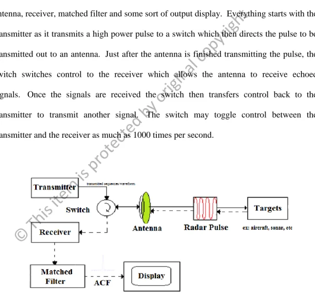
A basic radar system as shown in Figure 1.1 is spilt up into a transmitter, switch, antenna, receiver, matched filter and some sort of output display. Everything starts with the transmitter as it transmits a high power pulse to a switch which then directs the pulse to be transmitted out to an antenna. Just after the antenna is finished transmitting the pulse, the switch switches control to the receiver which allows the antenna to receive echoed signals. Once the signals are received the switch then transfers control back to the transmitter to transmit another signal. The switch may toggle control between the transmitter and the receiver as much as 1000 times per second.
Figure 1.1 Basic Pulse Compression Radar (Catania, G., Wonsuck Kim, et al. 2009)
© This
item is protecte d by
original
copyr
ight
7 1.3 Problem Statement
Sequences with favourable correlation properties like low out-of-phase auto- correlation values, low cross-correlation values, low nontrivial partial-period correlation values, large linear span, balance of symbols, large family size, ease of implementation and high energy ratios has increased dramatically in recent years.
The theory of sequences has found major applications in a wide variety of technological situations including secure, reliable and efficient communications, digital ranging and tracking systems, deterministic simulation of random processes and computer sequencing and timing schemes (Zhou, C. T. 2006). In addition, there is intense interest in the applications of Code Division Multiple Access (CDMA) and Orthogonal Frequency Division Multiple Access (OFDMA) signals for mobile and wireless communications (Srikanth, S., et al., 2004). In fact, essentially all the standards for third generation (3G) and fourth generation (4G) cellular telephony are based on CDMA and FDMA (4G - Wikipedia, 2011). It is a challenge to build the project thus, their practical importance of considerable research is being carried out to develop methods for the synthesis and design of these sequences. In spite of considerable effort that has been devoted to the problem of designing sequences with good correlation properties, there seems to be a lack of sequence design methods and theories.
Fundamental studies that provide the basis for technical advances have not, yet, solved the general signal design problem. All available methods tend to have an element of trial and error and also rely on the skill and ingenuity of the designer. Therefore, the signal design problem has in general defied solution by all means other than exhaustion. In particular, no concise set of necessary and sufficient conditions has been formulated
© This
item is protecte d by
original
copyr
ight