DAMPING PROPERTIES OF A357 ALLOYS AND A357-STAINLESS STEEL COMPOSITES FABRICATED UNDER DIFFERENT CONDITIONS
MAZLEE BIN MOHD NOOR
UNIVERSITI MALAYSIA PERLIS
2010
© T hi s it em is p ro te ct ed by o rig in al co py rig ht
Damping Properties of A357 Alloys And A357-Stainless Steel Composites Fabricated Under Different Conditions
by
Mazlee Bin Mohd Noor (0540410060)
A thesis submitted
in fulfilment of the requirements for the degree of Doctor of Philosophy
School of Materials Engineering UNIVERSITI MALAYSIA PERLIS
2010
© T hi s it em is p ro te ct ed by o rig in al co py rig ht
ii
ACKNOWLEDGEMENTS
I am glad to finally have the opportunity to convey my gratefulness to all those who were involved, directly or indirectly in making this work a success.
Firstly and foremost, I am very much indebted to my main supervisor, Prof.
Dr. Shamsul Baharin Jamaludin. It is my great pleasure to express my sincere thanks for his critical and motivating discussions, the extraordinary cooperativeness and support but also for enriching conversations about humanity and life. It has been my pleasure to work with him. I also would like to express my sincere appreciation to my co-supervisor, Brig. Gen. Dato’ Prof. Dr. Kamarudin Hussin for his motivational support and fruitful discussions.
I am grateful to Prof. Dr. Shahjahan Mridha, Kuliyyah of Engineering, International Islamic University Malaysia (IIUM) and Prof. Dr. Abdul Razak Daud, Faculty of Science and Technology, Universiti Kebangsaan Malaysia (UKM) for being external examiners and also Ir. Dr. Haftirman, School of Mechatronics Engineering, Universiti Malaysia Perlis (UniMAP) for being internal examiner for this thesis.
Many thanks for the scholarship awarded by Public Service Department, Malaysia throughout this study.
I also owe my appreciation to many other members of our institute as well as to some staffs. Here are the names of those who have substantially contributed to the successful completion of this particular work: Mr. Shaiful Rizam Shamsuddin, Mr.
Chek Idrus Omar, Mr. Azmi Aziz, Mr. Hadzrul Iqwan Jalaludin and Mr. Mohd Nasir Ibrahim.
© T hi s it em is p ro te ct ed by o rig in al co py rig ht
iii
Last but not least I would like to express my deep gratitude to my parents (Haji Mohd Noor Bin Sinawi and Hajah Salmah Binti Muslimin) who encouraged and supported me in all aspects. A very big thank you goes to my brothers (Mohamad Rizal and Muhammad Faizal) and sisters (Salizatunnor and Nur Suhaila) for their supports.
Above all I owe an extra special thank you to my beloved wife, Zunairah Binti Hasan and my children, Nur Athirah Amni, Muhammad Athiqh Fathullah and Muhammad Afhiqh Fathullah. Without their encouragement and continuous support, I would not have been able to complete my doctorate degree successfully.
© T hi s it em is p ro te ct ed by o rig in al co py rig ht
iv
TABLE OF CONTENTS
ACKNOWLEDGEMENTS
TABLE OF CONTENTS
LIST OF FIGURES
LIST OF TABLES
LIST OF ABBREVIATIONS ABSTRAK
ABSTRACT
ii iv x xvii xviii xix xx
CHAPTER 1 INTRODUCTION
1.1 Background……….
1.2 Problem Statements……….
1.3 Research Objectives………....
CHAPTER 2 LITERATURE REVIEW
2.1 Aluminium Alloys………...
2.1.1 History of Aluminium .………...
2.1.2 Introduction, Extraction and Production of
Aluminium Alloys………………
2.1.3 Aluminium Casting Alloys………...
2.1.4 Aluminium-Silicon (Al-Si) Alloys...
2.1.4.1 Phase Diagram of Aluminium-Silicon (Al-Si) System………
2.1.4.2 Aluminium-Silicon-Magnesium (Al-Si-Mg) Casting Alloys………...
1 3 4
5 5
6 9 12
12
14
© T hi s it em is p ro te ct ed by o rig in al co py rig ht
v
2.2 Reinforcements In Metal Matrix Composites (MMCs)……..
2.2.1 Types of Reinforcement ……….
2.2.1.1 Ceramic Reinforcements……….
2.2.1.2 Metallic Reinforcements………..
2.3 Metal Matrix Composites (MMCs)……….
2.3.1 Composite Materials………
2.3.2 Introduction to Metal Matrix Composites (MMCs)…
2.3.2.1 Aluminium Matrix Composites (AMCs)……
2.4 Processing of Metallic Alloys and Metal Matrix
Composites (MMCs)………...
2.4.1 Liquid State Processing………...
2.4.1.1 Casting………
2.4.1.1.1 Conventional Casting………..
2.4.1.1.2 Centrifugal Casting………….
2.4.1.1.3 Liquid Infiltration (LanxideTM Process)………...
2.4.1.2 Squeeze Casting………
2.4.1.3 Spray Co-Deposition………
2.4.1.4 In-Situ Process………..
2.4.2 Solid State Processing……….
2.4.2.1 Powder Metallurgy………...
2.4.2.2 Diffusion Bonding……….
2.4.2.2.1 Foil-Fibre-Foil Process………
2.4.2.2.2 Matrix Coated Fibre Process...
15 16 16 17 18 18 20 22
24 24 24 24 25
26 27 29 30 32 33 34 34 35
© T hi s it em is p ro te ct ed by o rig in al co py rig ht
vi
2.5 Microstructure of Cast Aluminium Alloys and
Aluminium Matrix Composites (AMCs)………
2.5.1 Cast Aluminium Alloys………...…
2.5.1.2 Intermetallic Phases…….………
2.5.2 Interface in Aluminium Matrix Composites
(AMCs)………
2.5.2.1 Nature of Interface………
2.5.2.2 Reaction of Interface………
2.5.3 Casting Modifications……….
2.5.3.1 Chemical Technique.………
2.5.3.1.1 Grain Modification…………..
2.5.3.2 Nonchemical Techniques……….
2.5.3.2.1 Melt Degassing………
2.5.3.2.2 Ultrasonic Vibration…………
2.5.3.2.3 Superheating………
2.6 Damping Properties of Aluminium Alloys and AMCs……...
2.6.1 Introduction……….
2.6.2 Definitions of Damping………...
2.6.3 Dynamic Mechanical Properties……….
2.6.3.1 Dynamic Moduli………
2.6.3.2 Damping Capacity………
2.6.3.2.1 Derivation of Damping
Capacity………
2.6.3.3 Types of Damping……….
37 38 40
42 44 45 48 48 48 50 50 51 51 53 53 54 56 56 57
58 62
© T hi s it em is p ro te ct ed by o rig in al co py rig ht
vii
2.6.3.3.1 Internal or Materials
Damping………..
2.6.3.3.2 Structural Damping………….
2.6.3.3.3 Fluid Damping……….
2.6.3.4 Measurement Techniques of Damping……….
2.6.3.4.1 Torsion Pendulum………...…
2.6.3.4.2 Cantilever Beam Technique…
2.6.3.4.3 Dynamic Mechanical
Thermal Analyzer………
2.6.3.5 Mechanisms of Damping……….
2.6.3.5.1 Dislocation Damping………...
2.6.3.5.2 Interfacial Damping………….
2.6.3.5.3 Grain Boundary Damping…...
2.6.3.5.4 Thermoelastic Damping……..
2.7 Differential Scanning Calorimetry (DSC)………...
2.7.1 Introduction……….
2.7.2 Determination of Precipitation Sequence………
2.7.3 Solidification Characterisation………
CHAPTER 3 EXPERIMENTAL PROCEDURE
3.1 Raw Materials……….
3.2 Classification of Specimens ………...
3.3 Fabrication Using Casting Technique……….
3.4 Characterisations and Testings………
3.4.1 Light Microscope………
63 64 64 65 65 66
67 68 69 71 72 72 73 73 74 75
79 81 81 86 86
© T hi s it em is p ro te ct ed by o rig in al co py rig ht
viii
3.4.2 Scanning Electron Microscope (SEM)………
3.4.3 Dynamic Mechanical Analyzer (DMA)………..
3.4.4 Differential Scanning Calorimetry (DSC)…………...
CHAPTER 4 RESULTS AND DISCUSSION
4.1 Microstructural Analysis………
4.1.1 Microstructure of Nonsuperheated and
Superheated A357 alloys……….
4.1.1.1 Solidification Phases……….
4.1.1.1.1 π-Al8FeMg3Si6 Intermetallic Phase……….
4.1.1.1.2 Mg2Si Phase………..
4.1.2 Microstructure of Superheated A357-0.5 and
1.0 wt.% Stainless Steel Composites……..………….
4.1.2.1 Nonexistence of Intermetallic Compound at the Matrix-Stainless Steel Reinforcement Interface………..
4.1.2.2 Interface………..
4.2 Analysis of Dynamic Mechanical Properties………...
4.2.1 Storage Modulus at Different Frequencies…………..
4.2.2 Loss Modulus at Different Frequencies………...
4.2.3 Damping Capacity at Different Frequencies…………
4.2.4 Mechanisms of Damping………..
4.2.4.1 Dislocation Damping……….…
4.2.4.2 Grain Boundary Damping………...
87 88 89
92
92 96
96 103
105
112 114 117 117 123 128 134 135 137
© T hi s it em is p ro te ct ed by o rig in al co py rig ht
ix
4.2.4.3 Interfacial Damping………..
4.3 Differential Scanning Calorimetry (DSC) Analysis………….
4.3.1 DSC Thermographs at Lower Temperatures…………
4.3.2 DSC Thermographs at Higher Temperatures………...
CHAPTER 5 CONCLUSIONS……….………
CHAPTER 6 SUGGESTION FOR FUTURE WORKS………
REFERENCES………...
APPENDICES Appendix A - Etchant for Etching Process.
Appendix B - List of Publications Arise from This Research.
138 139 140 143
147
150
151
© T hi s it em is p ro te ct ed by o rig in al co py rig ht
x
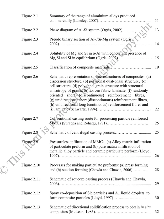
LIST OF FIGURES
Figure 2.1 Summary of the range of aluminium alloys produced
commercially (Lumley, 2007)……….... 11 Figure 2.2 Phase diagram of Al-Si system (Ogris, 2002)……….... 13 Figure 2.3 Pseudo binary section of Al-7Si-Mg system (Ogris,
2002)………... 14 Figure 2.4 Solubility of Mg and Si in α-Al with concurrent presence of
Mg2Si and Si in equilibrium (Ogris, 2002)………... 15 Figure 2.5 Classification of composite materials………... 19 Figure 2.6 Schematic representation of microstructures of composites: (a)
dispersion structure, (b) polygonal dual-phase structure, (c) cell structure, (d) polygonal grain structure with structural anisotropy of grains, (e) woven fabric laminate, (f) randomly oriented short (discontinuous) reinforcement fibres, (g) unidirectional short (discontinuous) reinforcement fibres, (h) unidirectional long (continuous) reinforcement fibres and (i) laminate (Schwartz, 1994)……….… 22 Figure 2.7 Conventional casting route for processing particle reinforced
MMCs (Surappa and Rohatgi, 1981)………. 25 Figure 2.8 Schematic of centrifugal casting process……….…... 25 Figure 2.9 Pressureless infiltration of MMCs; (a) Alloy matrix infiltration
of particulate preform and (b) pure matrix infiltration of metallic alloy particle and ceramic particulate perform (Lloyd, 1997)………... 26 Figure 2.10 Processes for making particulate preforms: (a) press forming
and (b) suction forming (Chawla and Chawla, 2006)………… 28 Figure 2.11 Schematic of squeeze casting process (Chawla and Chawla,
2006)………... 29 Figure 2.12 Spray co-deposition of Sic particles and A1 liquid droplets, to
form composite particles (Lloyd, 1997)……... 30 Figure 2.13 Schematic of directional solidification process to obtain in situ
composites (McLean, 1983)………... 32
© T hi s it em is p ro te ct ed by o rig in al co py rig ht
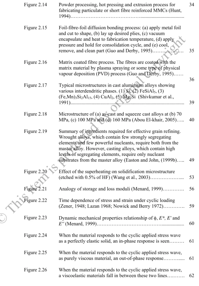
xi
Figure 2.14 Powder processing, hot pressing and extrusion process for fabricating particulate or short fibre reinforced MMCs (Hunt, 1994)………...
34
Figure 2.15 Foil-fibre-foil diffusion bonding process: (a) apply metal foil and cut to shape, (b) lay up desired plies, (c) vacuum
encapsulate and heat to fabrication temperature, (d) apply pressure and hold for consolidation cycle, and (e) cool,
remove, and clean part (Guo and Derby, 1995)………. 35 Figure 2.16 Matrix coated fibre process. The fibres are coated with the
matrix material by plasma spraying or some type of physical vapour deposition (PVD) process (Guo and Derby, 1995)……
36 Figure 2.17 Typical microstructures in cast aluminium alloys showing
various interdendritic phases. (1) Si, (2) FeSiAl5, (3) (Fe,Mn)3Si2Al15, (4) CuAl2, (5) Mg2Si (Shivkumar et al.,
1991)... 39 Figure 2.18 Microstructure of (a) as-cast and squeeze cast alloys at (b) 70
MPa, (c) 100 MPa and (d) 160 MPa (Abou El-khair, 2005)….. 40 Figure 2.19 Summary of ingredients required for effective grain refining.
Wrought alloys, which contain few strongly segregating elements and few powerful nucleants, require both from the master alloy. However, casting alloys, which contain high levels of segregating elements, require only nucleant
substrates from the master alloy (Easton and John, (1999b)….. 49 Figure 2.20 Effect of the superheating on solidification microstructure
(etched with 0.5% of HF) (Wang et al., 2003)………... 53 Figure 2.21 Analogy of storage and loss moduli (Menard, 1999)…………. 56 Figure 2.22 Time dependence of stress and strain under cyclic loading
(Zener, 1948; Lazan 1968; Nowick and Berry 1972)…………. 59 Figure 2.23 Dynamic mechanical properties relationship of , E*, E' and
E'' (Menard, 1999)………... 60 Figure 2.24 When the material responds to the cyclic applied stress wave
as a perfectly elastic solid, an in-phase response is seen……… 61 Figure 2.25 When the material responds to the cyclic applied stress wave,
as purely viscous material, an out-of-phase response………... 61 Figure 2.26 When the material responds to the cyclic applied stress wave,
a viscoelastic materials fall in between these two lines….……. 62
© T hi s it em is p ro te ct ed by o rig in al co py rig ht
xii Figure 2.27
Figure 2.28
Figure 2.29
A typical hysteresis loop for mechanical damping (Silva, 2000)………...
Schematic diagram showing a torsion pendulum (Kê, 1947, Batist, 1972, Nowick and Berry, 1972)………..
Schematic diagram showing DMTA setup (Read, Dean and 64
66
Duncan, 1986; Lavernia et al., 1994)………. 67 Figure 2.30 Dislocation string model illustrating the bowing out and
breakaway of dislocation segments by an increasing applied
stress, σ (Granato and Lűcke, 1956)……….…… 70 Figure 2.31
Figure 2.32
Figure 2.33
Figure 2.34
Diffusion-controlled movement of foreign atoms from a dislocation line at increasing temperature (Riehemann, 1994)………...
Typical DSC thermograms for an as-cast A357 alloy
with Sr modification (Wang and Davidson, 2001)………….…
DSC thermographs showing the effect of Mg addition on the melting/solidification behaviour in heating of A356 (356Sr) and A357 (357Sr) alloys with Sr modification (Wang and Davidson, 2001)……….…….
Comparison of DSC thermographs between the as-cast and the solution treated A357 alloy with Sr modification (Wang and Davidson, 2001)……….….
71
76
76
77 Figure 3.1
Figure 3.2 Figure 3.3
Figure 3.4
Primary cast ingot Al-Si-Mg alloy ………
Continuous 304 stainless steel wires ………
The furnaces used in casting process; (a) muffle furnace and (b) preheated furnace ……….
Schematic arrangement of 304 stainless steel wires (SSw) to produce as-cast composites; plan view of (a) A357-0.5 wt. % stainless steel composite and (b) A357-0.5 wt. % stainless steel composite………...
80 80
82
83 Figure 3.5 (a) Schematic arrangement of 304 stainless steel wires (SSw) to
produce as-cast composites; side view of A357-0.5 wt. %
stainless steel composite………. 83 Figure 3.5 (b) Schematic arrangement of 304 stainless steel wires (SSw) to
produce as-cast composites; side view of A357-1.0 wt. %
stainless steel composite………. 84
© T hi s it em is p ro te ct ed by o rig in al co py rig ht
xiii
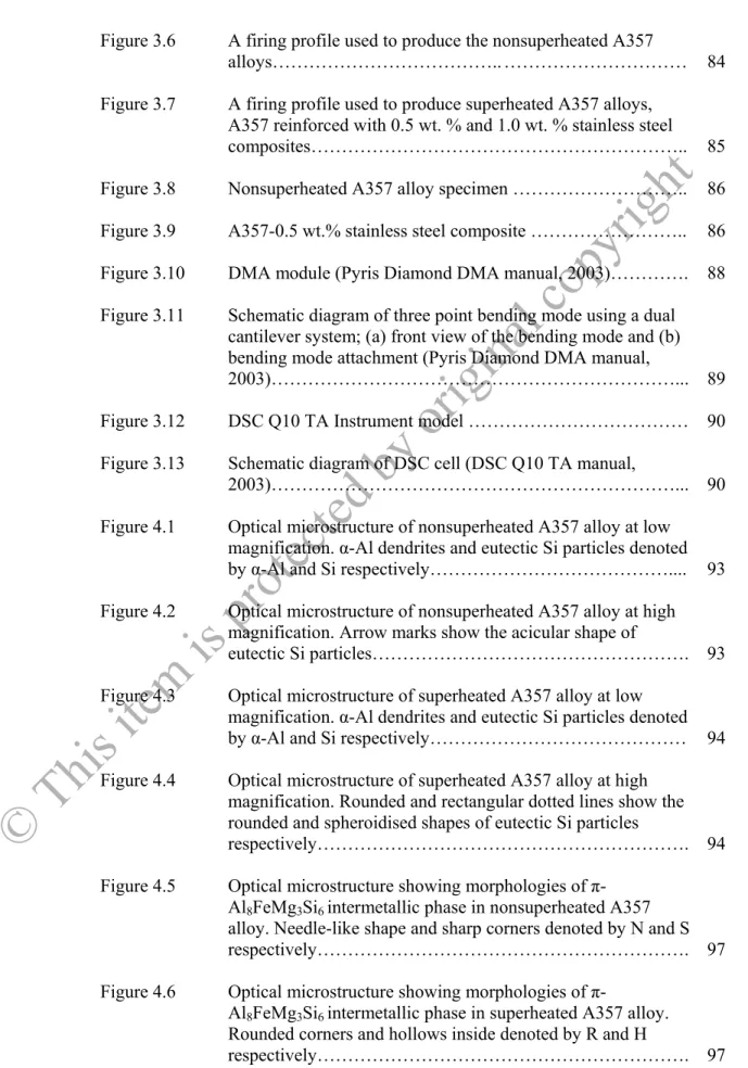
Figure 3.6 A firing profile used to produce the nonsuperheated A357
alloys……….. ……… 84
Figure 3.7
Figure 3.8 Figure 3.9
A firing profile used to produce superheated A357 alloys, A357 reinforced with 0.5 wt. % and 1.0 wt. % stainless steel composites………..
Nonsuperheated A357 alloy specimen ………..
A357-0.5 wt.% stainless steel composite ………..
85 86 86 Figure 3.10 DMA module (Pyris Diamond DMA manual, 2003)…………. 88 Figure 3.11
Figure 3.12
Schematic diagram of three point bending mode using a dual cantilever system; (a) front view of the bending mode and (b) bending mode attachment (Pyris Diamond DMA manual, 2003)………...
DSC Q10 TA Instrument model ………
89 90 Figure 3.13 Schematic diagram of DSC cell (DSC Q10 TA manual,
2003)………... 90
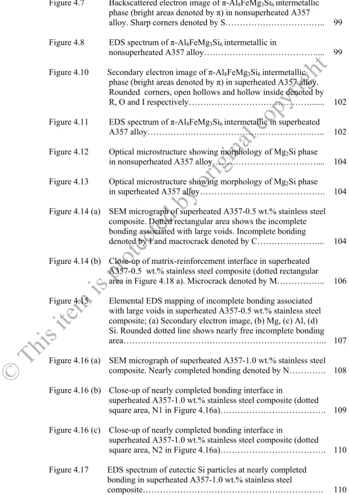
Figure 4.1 Optical microstructure of nonsuperheated A357 alloy at low magnification. α-Al dendrites and eutectic Si particles denoted by α-Al and Si respectively……….... 93 Figure 4.2 Optical microstructure of nonsuperheated A357 alloy at high
magnification. Arrow marks show the acicular shape of
eutectic Si particles………. 93 Figure 4.3 Optical microstructure of superheated A357 alloy at low
magnification. α-Al dendrites and eutectic Si particles denoted by α-Al and Si respectively……… 94 Figure 4.4 Optical microstructure of superheated A357 alloy at high
magnification. Rounded and rectangular dotted lines show the rounded and spheroidised shapes of eutectic Si particles
respectively………. 94 Figure 4.5 Optical microstructure showing morphologies of π-
Al8FeMg3Si6 intermetallic phase in nonsuperheated A357 alloy. Needle-like shape and sharp corners denoted by N and S respectively………. 97 Figure 4.6 Optical microstructure showing morphologies of π-
Al8FeMg3Si6 intermetallic phase in superheated A357 alloy.
Rounded corners and hollows inside denoted by R and H
respectively………. 97
© T hi s it em is p ro te ct ed by o rig in al co py rig ht
xiv
Figure 4.7 Backscattered electron image of π-Al8FeMg3Si6 intermetallic phase (bright areas denoted by π) in nonsuperheated A357
alloy. Sharp corners denoted by S……….. 99 Figure 4.8 EDS spectrum of π-Al8FeMg3Si6 intermetallic in
nonsuperheated A357 alloy……….... 99 Figure 4.10 Secondary electron image of π-Al8FeMg3Si6 intermetallic
phase (bright areas denoted by π) in superheated A357 alloy.
Rounded corners, open hollows and hollow inside denoted by R, O and I respectively………... 102 Figure 4.11 EDS spectrum of π-Al8FeMg3Si6 intermetallic in superheated
A357 alloy……….. 102
Figure 4.12 Optical microstructure showing morphology of Mg2Si phase
in nonsuperheated A357 alloy……….... 104 Figure 4.13 Optical microstructure showing morphology of Mg2Si phase
in superheated A357 alloy……….. 104 Figure 4.14 (a) SEM micrograph of superheated A357-0.5 wt.% stainless steel
composite. Dotted rectangular area shows the incomplete bonding associated with large voids. Incomplete bonding
denoted by I and macrocrack denoted by C………... 104 Figure 4.14 (b) Close-up of matrix-reinforcement interface in superheated
A357-0.5 wt.% stainless steel composite (dotted rectangular
area in Figure 4.18 a). Microcrack denoted by M……….. 106 Figure 4.15 Elemental EDS mapping of incomplete bonding associated
with large voids in superheated A357-0.5 wt.% stainless steel composite; (a) Secondary electron image, (b) Mg, (c) Al, (d) Si. Rounded dotted line shows nearly free incomplete bonding
area……….. 107
Figure 4.16 (a) SEM micrograph of superheated A357-1.0 wt.% stainless steel composite. Nearly completed bonding denoted by N…………. 108 Figure 4.16 (b) Close-up of nearly completed bonding interface in
superheated A357-1.0 wt.% stainless steel composite (dotted
square area, N1 in Figure 4.16a)………. 109 Figure 4.16 (c) Close-up of nearly completed bonding interface in
superheated A357-1.0 wt.% stainless steel composite (dotted
square area, N2 in Figure 4.16a)………. 110 Figure 4.17 EDS spectrum of eutectic Si particles at nearly completed
bonding in superheated A357-1.0 wt.% stainless steel
composite……… 110
© T hi s it em is p ro te ct ed by o rig in al co py rig ht
xv
Figure 4.18 Elemental EDS mapping of nearly completed bonding in superheated A357-1.0 wt.% stainless steel composite;
(a) Secondary electron image, (b) Mg, (c) Al, (d) Si………….. 111 Figure 4.19 SEM micrograph showing the π-Al8FeMg3Si6 intermetallics
phase (bright particles) around a stainless steel wire in
superheated A357-0.5 wt. % stainless steel composite……….. 113 Figure 4.20 SEM micrograph showing the π-Al8FeMg3Si6 intermetallics
(bright particles)around a stainless steel wire in superheated
A357-1.0 wt. % stainless steel composite……….. 113 Figure 4.21 Storage modulus of nonsuperheated A357 alloy at different
frequencies……….. 119 Figure 4.22 Storage modulus of superheated A357 alloy at different
frequencies……….. 119 Figure 4.23 Storage modulus of superheated A357 alloy-0.5 wt. %
stainless steel composite at different frequencies………... 120 Figure 4.24 Storage modulus of superheated A357 alloy-1.0 wt. %
stainless steel composite at different frequencies………... 120 Figure 4.25 Crack propagation into the matrix alloy started from the void
close to the stainless steel reinforcement (SSw)………. 123 Figure 4.26 Loss modulus of nonsuperheated A357 alloy at different
frequencies……….. 125 Figure 4.27 Loss modulus of superheated A357 alloy at different
frequencies……….. 125 Figure 4.28 Loss modulus of superheated A357 alloy-0.5 wt. % stainless
steel composite at different frequencies………. 126 Figure 4.29 Loss modulus of superheated A357 alloy-1.0 wt. % stainless
steel composite at different frequencies………. 126 Figure 4.30 Damping capacity of nonsuperheated A357 alloy at different
frequencies……….. 131 Figure 4.31 Damping capacity of superheated A357 alloy at different
frequencies……….. 131 Figure 4.32 Damping capacity of superheated A357 alloy-0.5 wt. %
stainless steel composite at different frequencies………... 132 Figure 4.33 Damping capacity of superheated A357 alloy-1.0 wt. %
stainless steel composite at different frequencies………... 132
© T hi s it em is p ro te ct ed by o rig in al co py rig ht
xvi
Figure 4.34 DSC thermographs of nonsuperheated and superheated A357 alloys (NS A357 CP and S A357 CP respectively) and after
casting process from 100 to 450ºC………. 141 Figure 4.35 DSC thermographs of superheated A357-0.5 and 1.0 wt.%
stainless steel composites (0.5 wt.% CP and 1.0 wt.% CP
respectively) after casting process from 100 to 450ºC………... 141 Figure 4.36 DSC thermographs of nonsuperheated and superheated A357
alloys (NS A357 ST and S A357 ST respectively) after
solution treatment from 100 to 450ºC……… 142 Figure 4.37 DSC thermographs of superheated A357-0.5 and 1.0 wt.%
stainless steel composites (0.5 wt.% ST and 1.0 wt.% ST
respectively) after solution treatment from 100 to 450ºC…….. 142 Figure 4.38 DSC thermographs of superheated A357-0.5 and 1.0 wt.%
stainless steel composites (0.5 wt.% ST and 1.0 wt.% ST
respectively) after solution treatment from 100 to 450ºC…….. 144 Figure 4.39 DSC thermographs of superheated A357-0.5 and 1.0 wt.%
stainless steel composites (0.5 wt.% CP and 1.0 wt.% CP
respectively) after casting process from 530 to 630ºC………... 144 Figure 4.40 DSC thermographs of nonsuperheated and superheated A357
alloys (NS A357 ST and S A357 ST respectively) after
solution treatment from 530 to 630ºC……… 145 Figure 4.41 DSC thermographs of superheated A357-0.5 and 1.0 wt.%
stainless steel composites (0.5 wt.% ST and 1.0 wt.% ST
respectively) after solution treatment from 530 to 630ºC…….. 145
© T hi s it em is p ro te ct ed by o rig in al co py rig ht
xvii
LIST OF TABLES
Table 2.1 Characteristics of aluminium and relative importance in
different products (Lumley, 2007)……….... 7 Table 2.2 Type of product of aluminium and relative importance in
different products (Lumley, 2007)………... 7 Table 2.3 Aluminium casting alloy groups………... 11 Table 2.4 Types of main reinforcements used in MMCs (Mykura,
1991)………... 16
Table 2.5 Properties of SiC and Al2O3 reinforcements (Lloyd,
1994)………... 17
Table 2.6 Physical properties of metallic reinforcements (Vinson and
Chon, 1975)……… 18
Table 2.7 Potential and realistic technical applications of MMCs
(Kainer, 2006)……… 21
Table 2.8 Applications of AMCs………... 23 Table 2.9 Solidification reactions observed in A356/A357 alloys
(Wang and Davidson, 2001)………...……… 77 Table 3.1 Chemical compositions of primary cast ingot A357……….. 80 Table 3.2 Chemical compositions of 304 stainless steel wire………… 80 Table 4.1 Analysis of selected specimen data of storage modulus at 1
Hz frequency……….. 122
Table 4.2 Analysis of selected specimen data of loss modulus at 1Hz
frequency……… 127
Table 4.3 Analysis of selected specimen data of damping capacity at
1 Hz frequency………... 134
© T hi s it em is p ro te ct ed by o rig in al co py rig ht
xviii
LIST OF ABBREVIATIONS
MMCs : Metal matrix composites.
PMCs : Polymer matrix composites.
CMCs : Ceramic matrix composites.
AMCs : Aluminium matrix composites.
SEM : Scanning electron microscopy.
EDS : Energy dispersive spectrometry.
DMA : Dynamic mechanical analyzer.
DMTA : Dynamic mechanical thermal analyzer.
DSC : Differential scanning calorimetry.
SSw : Stainless steel wire.
CTE : Coefficient of thermal expansion.
ECAP : Equal channel angular pressing.
GP zones : Guinier-Preston zones
© T hi s it em is p ro te ct ed by o rig in al co py rig ht
xx
DAMPING PROPERTIES OF A357 ALLOYS AND A357-STAINLESS STEEL COMPOSITES FABRICATED
UNDER DIFFERENT CONDITIONS
ABSTRACT
The lab scale gravity casting technique was used to produce alloy specimens of nonsuperheated A357 alloy, superheated A357 alloy and composite specimens of superheated A357-0.5 and 1.0 wt.% stainless steel composites. The primary cast ingot A357 alloy was melted in graphite crucible before pouring into the stainless steel mould at 700ºC for all specimens. Meanwhile, prior to pouring, the preform of 304 stainless steel wires were aligned in stainless steel mould to produce superheated A357-0.5 and 1.0 wt.% stainless steel composites respectively. The main objective of this research is to study the effect of superheating on the microstructures and dynamic mechanical properties, to identify the phases that presents in all the specimens and also to identify the appropriate damping mechanisms in all specimens at lower and elevated temperatures. The superheating had refined the eutectic Si particles and changed the shapes of α-Al dendrites in superheated A357 alloys. The superheating also changed the shapes of π-Al8FeMg3Si6 intermetallic phase and Mg2Si phase in superheated A357 alloys. Superheated A357-0.5 wt.% stainless steel composite showed poor bonding and less intensified of coarser eutectic Si particles around the matrix-reinforcement interface. Superheated A357-1.0 wt.% stainless steel composite showed good bonding and more intensified of finer eutectic Si particles around the matrix-reinforcement interface. However, no interface reaction layer was observed at the matrix-reinforcement interface of the composite specimens. Dynamic mechanical properties such as storage modulus, loss modulus and damping capacity were investigated by dynamic mechanical analyzer (DMA). Superheated A357-1.0 wt.%
stainless steel composite showed the highest storage modulus of 66.30 GPa at 50ºC.
Superheated A357-0.5 wt.% stainless steel composite showed the highest loss modulus of 4.10 GPa at 380ºC. Superheated A357 alloys showed the highest damping capacity of 0.0842 GPa at 380ºC. Dislocation damping was the mechanism at lower temperatures range (50 to 280ºC) for the alloys and the composites. Meanwhile, grain boundary damping and interfacial damping were the mechanisms at elevated temperatures range (281 to 380ºC) for the composite and only grain boundary damping was the mechanism at elevated temperature range for the alloys. Differential scanning calorimetry (DSC) study at lower temperatures range (100 to 450ºC) of solution treated alloys and composite specimens showed the presence of two exothermic reactions (precipitation of θ″ and θ′) and an endothermic reaction (dissolution of θ″) while at elevated temperatures range (530 to 630ºC) of solution treated alloys and composite specimens showed three endothermic reactions (Al dendrites, Al + Si and Al + Si + Mg2Si + π-Al8FeMg3Si6).
© T hi s it em is p ro te ct ed by o rig in al co py rig ht
1
CHAPTER 1
INTRODUCTION
1.1 Background
Dynamic mechanical properties which represented by dynamic moduli (storage modulus and loss modulus) and damping capacity remain the prime importance in many engineering fields particularly which exposed to the dynamic applications. Knowledge of damping in a dynamic behaviour is essential in utilisation, analysis and testing of the components.
The damping capacity is the capacity of a material to convert mechanical energy of vibrations into heat that is dissipated in the materials (Rohatgi et al., 1994).
When a high damping materials is effectively utilised in a structure exposed to a cyclic loading, this property allows undesirable noise and vibration to be passively attenuated and remove to the surroundings as heat (Perez et al, 1993). The damping mechanism of materials is also become practical significant as the degree of damping affects the mechanism under cyclic loading.
In metals and alloys, damping capacity can be improved by the addition of the reinforcements. Aluminium alloys have low damping capacity values in the range of 0.40 to 0.70 x 10⁻³ compared to other alloys such as steel (1.60 to 4.80 x 10⁻³) and
© T hi s it em is p ro te ct ed by o rig in al co py rig ht
2
magnesium (39.80 to 79.60 x 10⁻³) (Zhang et al. 1993a). Previously, the damping capacity of Al-4 wt.% Cu alloys progressively increases with increasing amounts of mica particles dispersed in the matrix reported by Deonath et al. (1981). According to finding by Perez et al. (1993), the damping capacity of the Al 6061 alloy was increased with increasing volume fraction of graphite particles. The latest investigation was found by Wanga et al. (2009) on the improvement of damping capacity in Li5La3Ta2O12 particulates reinforced aluminum matrix composites (AMCs).
The measurement of damping capacity in the discontinuous particles reinforced AMCs were widely done as previously mentioned. However, very limited measurement of damping capacity was carried out in continuous fibre reinforced aluminium composites. One of the measurements of damping capacity in the continuous fibre reinforced aluminium composites was reported by Wolfenden and Wolla (1989) on the alumina and tungsten continuous fibre reinforced aluminium composites.
Al–Si alloys as important light metals are widely used in automotive, transportation, construction and leisure industry due to their excellent wear resistance, pressure tightness, fluidity, and shrinkage (Ejiofor & Reddy, 1997). It was reported that Al–Si alloys had relative low damping capacity (Zhang et. al, 1993b), which largely limited their application in both high damping capacity and mechanical properties needed. However, various methods to improve damping capacity were accompanied by decreasing in strength (Perez et al., 1993; Zhang et al., 1994; Wei et al., 2002). Therefore, further studies are still of necessity for Al–Si alloys to achieve significant improvement in both damping capacity and mechanical properties.
© T hi s it em is p ro te ct ed by o rig in al co py rig ht
3
The damping capacity of the alloys can be improved by microstructural modification. Improvement of damping capacity was achieved by grain refinement in A356 alloy with grain refiner (Zhang et al., 2005; Zhang et al., 2008) and ultrafine- grained in pure aluminium L2 by combination of equal channel angular pressing (ECAP) and annealing process (Zhang et al., 2006). Improvement of damping capacity also was achieved by formation of GP zone with the application of age hardening on Al-7Si-0.3Mg alloy (Lee, 2005).
1.2 Problem Statements
In this study, several scientific curiosities have led to the problem statements as follows:
1. In general, aluminium alloys are weak in strength, modulus and hardness compared to steel (Zhang et al., 2005). So, it is necessary to develop new aluminium matrix composite to overcome these problems.
2. Very few investigations of damping capacity in continuous aluminium matrix composites (AMCs) were reported (Wolfenden and Wolla, 1989). However, none of the research was done on the measurement of damping capacity and damping mechanisms in the continuous wire reinforced AMCs particularly on the application of the dynamic force in the parallel direction to the continuous reinforcement.
3. Microstructure plays an important role in determining the resulted damping capacity (Srikanth et al., 2004). Different types of MMCs either produced by powder metallurgy or casting technique will
© T hi s it em is p ro te ct ed by o rig in al co py rig ht
4
influence the damping capacity. So, it is necessary to control the microstructure to produce the optimum damping capacity.
1.3 Research Objectives
In the present work, several research objectives are proposed according to the problems in the areas of MMCs:
1. To analyse the resulted microstructure that took place in nonsuperheated A357 alloy, superheated A357 alloy and composite specimens of superheated A357-0.5 and 1.0 wt.% stainless steel composites.
2. To study and analyse the storage modulus, loss modulus and damping capacity in nonsuperheated A357 alloy, superheated A357 alloy and composite specimens of superheated A357-0.5 and 1.0 wt.% stainless steel composites.
3. To identify the appropriate damping mechanisms in the alloys and composites from 50º to 380ºC.
4. To correlate the microstructure and damping properties in nonsuperheated A357 alloy, superheated A357 alloy and composite specimens of superheated A357-0.5 and 1.0 wt.% stainless steel composites.
5. To identify the phases that present in alloys and composites by using differential scanning calorimetry (DSC).
