Low Noise Amplifier at 5.8GHz with Cascode and Cascaded Techniques Using T-Matching Network for Wireless Applications.
Teks penuh
Gambar
Dokumen terkait
3, power gains of 2-port circuit network with power impedance or load impedance at power amplifier represented with scattering coefficient are classified into Operating
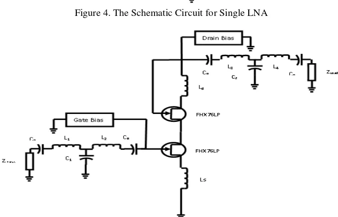
The design of the front-end low noise amplifier (LNA) is one of the challenges in radio frequency (RF) receivers, which needs to provide good input impedance match, enough power
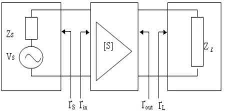
Several power gains were defined in order to understand the operation of super high frequency amplifier, as shown in Figure 2, power gains of 2-port circuit network with
The design of the front-end low noise amplifier (LNA) is one of the challenges in radio frequency (RF) receivers, which needs to provide good input impedance match,
Several power gains were deined in order to understand operation of super high frequency ampliier, as shown in Figure 2, power gains of 2-port circuit network with
Several power gains were defined in order to understand operation of super high frequency amplifier, as shown in Figure 2, power gains of 2-port circuit network with power impedance
Several power gains are defined to understand operation of super high frequency amplifier, as shown in Figure 2.2, power gains of 2 port circuit network with power impedance or
Several power gains were deined in order to understand operation of super high frequency ampliier, as shown in Figure 2, power gains of 2 port circuit network with
