Department of Software Engineering FSIT SWE-431 Project / Thesis Project Documentation
Consumer Complain Tracking System (CCTS)
Supervised by:
Mr. Md. Anwar Hossen Senior Lecturer
Department of Software Engineering
Daffodil International University
Submitted by:
Md. Aawlad Hossain
ID: 152-35-1216
Department of Software Engineering
Daffodil International University
DECLARATION
I hereby declare that, this project has been done by me under the supervision of Md. Anwar Hossen, Senior Lecturer, Department of Software Engineering, Daffodil International University. I also declare that neither this project nor any part of this project has been submitted elsewhere for award of any degree or diploma.
Md. Aawlad Hossain ID: 152-35-1216
Department of Software Engineering Daffodil International University
Certified by:
Md. Anwar Hossen Senior Lecturer
Department of Software Engineering
Faculty of Science & Information Technology Daffodil International University
ACKNOWLEDGEMENT
At first, I want to thank my almighty Allah. The success and final-outcome of this project required a lot of guidance and assistance from many people and I am extremely privileged to have got this all along the completion of my project. All that I have done is only due to such supervision and assistance and I would not forget to thank them. Besides, I am so much thankful to my parents who are always inspired me to reach this stage.
I respect and thank Mr. Md. Anwar Hossen and Marzia Zaman also I want to include here the main head of the project and our respectful Dean sir, Professor Dr. M. Shamsul Alam for providing me with an opportunity to do the project work in Consumer Complain Tracking System (CCTS) and giving us all support and guidance, which made me complete the project duly.
Proposed System Model
A software process model is a simplified representation of a software process.
Each model represents a process from a specific perspective.
Agile-Model
My proposed system model is agile model, which is an incremental process of software development. Each iteration lasts one to three weeks on average.
Engineering actions are carried out by cross-functional teams. In software development, the term “Agile” means the ability to respond to changes-changes from requirements, technology and people.
Figure: Agile-Model
Table of Contents
Acknowledgement ... ii
Proposed System Model ... iv
Agile-Model ... iv
Chapter 1: Introduction ... 1
1.1 Purpose and Scope ... 1
1.2 Overview of the Document ... 1
1.3 General Constraints ... 2
1.4 Goals and Guidelines ... 2
Chapter 2: System Architecture Description ... 3
2.1 Overview of Modules and Components ... 3
Chapter 3: Architectural Design and Sequence Diagrams ... 4
3.1 Architectural Representation... 4
Software architectural diagram of the system: - ... 5
Chapter 4: Glossary ... 6
Chapter 5: User Classes & Characteristics ... 7
5.1 Administrator ... 7
5.2 Call Representative ... 7
5.3 Cab Representative ... 7
Chapter 6: Design & Implementation Constraints ... 7
6.1 Operating Environment: ... 8
6.2 Software Language Used: ... 8
6.3 Development Tools: ... 8
6.4 Database Support: ... 8
Chapter 7: Assumptions & Dependencies ... 8
7.1 Data Entry ... 8
7.2 Hardware Dependencies ... 9
7.3 Browser Dependencies ... 9
Chapter 8: Benefits & Beneficiaries Benefits ... 9
8.1 Benefits: ... 9
8.2 Beneficiaries: ... 9
Chapter 9: Stakeholders ... 9
Chapter 10: Functional Requirements... 10
10.1 User Authentication Requirements ... 10
10.2 Data Entry Requirements ... 11
10.3 Dependability Requirements ... 11
10.3.1 Reliability Requirements ... 11
10.3.2 Availability Requirements ... 11
10.4 Maintainability and Supportability Requirements ... 12
10.4.1 Maintenance Requirements ... 12
10.4.2 Supportive Requirements ... 12
10.5 Security Requirements ... 12
10.6 Non-Functional Requirements ... 12
10.6.1 Performance Requirements ... 12
10.6.2 Safety Requirements ... 13
10.6.3 Security Requirements ... 13
10.6.4 Maintainability Requirements ... 13
Chapter 11: Gantt Chart ... 13
11.1 Release Plan or Milestone... 14
Chapter 12: List of Figure ... 15
12. Activity Diagram ... 15
12.1 Activity Diagram of Call (REP) ... 16
12.2 Activity Diagram of Admin ... 16
12.3 Activity Diagram of CAB Representative ... 18
Chapter 13: Sequence Diagram ... 19
13.1 Sequence Diagram of Call Representative ... 19
13.2 Sequence Diagram of Admin ... 20
13.3 Sequence Diagram of CAB Representative ... 20
Chapter 14: Data Flow Diagram ... 21
14.1 Context Diagram ... 21
Chapter 15: Use Case Diagrams ... 22
15.1 Use Case Diagram of User Authentication ... 22
15.2 Use Case Diagram of Admin ... 23
15.3 Use Case Diagram of Call Representative ... 25
15.4 Use Case Diagram of CAB Representative ... 30
16. ER Diagram ... 32
17. Class Diagram ... 34
18. Model Class Diagram ... 35
19.0 User Interface and Manuals ... 36
19.1 User Login... 36
19.2 Admin Dashboard ... 37
19.2.1 Admin Case Assign to CAB Officer ... 37
19.3 Call Representative UI ... 38
19.3.1 Create Consumer ... 38
19.3.1 Consumer List ... 38
19.4 Case Entry ... 39
19.4.1 Case List ... 39
19.7 Create Cab Activity ... 40
19.8 Consumer Feedback ... 40
19.9 List of Consumer Feedback ... 41
19.10 Contact Information ... 41
19.11 Contact Information List... 42
19.12 Call Representative send email to consumer ... 42
19.12.1 View email ... 43
19.13 CAB Officer Assign Case List ... 43
19.14 CAB Feedback UI ... 44
Chapter 20: User Manual ... 45
Reference: ... 45
Chapter 21: Conclusion ... 46
Chapter 1: Introduction
This section provides an overall bird’s eye view of the system. It defines what the system is Supposed to do and what the system will cover, as well as what the system will not include. It also includes a brief overview of the whole document.
1.1 Purpose and Scope
Consumer Complain Tracking System (CCTS) is a Web application for consumer right. Where consumer can inform to the call representative of CCTS over the phone, mobile. Any type of complain that he/she is facing or he/she have faced, for example, Food problem of any restaurant, super shop. Like Residence, Medical, Medicine, Furniture, Electricity, Electrical Item, ICT Item.
Call representative he/she will collect needed data from consumer. Intervals of
15 days call representative will inform to the consumer that what the present situation of his/her case.
Call representative send the case data to the consumer by email from the application. And all the cases are monitoring and evaluation by CAB officer.
Admin can assign case to the CAB representative for investigation.
This system is not only a part of data entry of consumer complain but also by this data anyone can research about cases why it’s happened how can decrease the case problem of consumer.
The system needs to have the ability to add/edit cases, consumer add, cab officer add, Contact information.
• The system will have the feature to send email to the cab officer.
• The system should have analysis of the case data with bar chart in dashboard.
1.2 Overview of the Document
The document aims to provide an insight into the overall design of the whole system. The whole document is divided into 10 chapters. Each of the chapters will describe different aspects of the design.
Table: 1.2 Overview of the Document
1.3 General Constraints
The general constraints on the development of the system are as follows:
The system will not be accessible to unauthorized users.
• All data save to the central database.
• The system will be completed by the end of April 2019.
• This project is developed by following Agile Methodology.
1.4 Goals and Guidelines
The goals of the SIS are to deliver the following:
Central, up-to-date repository of information on all cases and consumer information, all history of consumer and complain person or organization, cases, CAB activities information, solve cases history that is easy to access and manage.
It is an efficient and effective consumer problem solver web project and increase consumer rights.
. A tool where data is safe and secure.
A well-designed system that can handle thousands of concurrent Consumer cases.
Chapter 2: System Architecture Description
The core models and functionalities which are derived from the functional requirements are generated as some basic components of the systems. By this section it will be very clear for the development team to find out all these at a glance.
2.1 Overview of Modules and Components
Consumer Complain Tracking System should have the nine basic modules and some sub modules under the basic modules-
Fig 2.1: Basic Modules of the Student Information System
Chapter 3: Architectural Design and Sequence Diagrams
In this section the business and data layer activities are shown by which the non-functional.
Requirements are fulfilled and ease to the vendor to realize the system as well.
3.1 Architectural Representation
Here, the architectural representation is shown through the following figure.
Fig: 3.1 Access Layer of CCTS
3.2 Software architectural diagram of the system:
Fig: 3.2 Architectural Representations of whole system
Chapter 4: Glossary
Here there are some clarifications of the terms uses in this documents and also some explanation related to Consumer Complain Tracking System (CCTS).
Terms Definition
Consumer Create Call Representative can create a consumer.
Case Entry A set of Complain, Consumer provide data to the call representative.one consumer can complain about more then one.
Contact Information This information is about Call Representative and Cab Representative.
Call Representative Call Representative’s roles as a data entry operator.
CAB CAB means Consumers Association of Bangladesh. CAB call
center is operational now at DIU to help consumers resolve their issues as a consumer with any organization or person. It is a non-profit organization
Assign Case By the consumer complain Admin will assign case to the Cab representative to investigation.
Chapter 5: User Classes & Characteristics
5.1 Administrator
Admin of CCTS can assign a CAB representative for a single case or multiple cases, CAB representative look after the cases, and investigate the case. Admin can see the all analysis data from dashboard and all report.
5.2 Call Representative
User means Call Representative, user collect to the data of consumer and case. He can view and edit consumer data, case data, contact information, consumer feedback. User provide data to the database by CCTS. But he is not able to see dashboard and he have no access to assign any CAB representative for any cases.
5.3 Cab Representative
Cab Representative’s roles is that he/she will assign by admin for investigation of assigned cases.
Chapter 6: Design & Implementation Constraints
6.1 Operating Environment:
The CCTS for CAB will be web-based system. Thus, anyone having a browser can hit the specific link and can get access to it. Thus, it will ensure its best usage and will ease the means of getting access to the system. Moreover, it will remove the complexities of running the system in multiple platforms as it will be deployed in a web server.
6.2 Software Language Used:
The application will be developed using Microsoft’s Asp.NET Core MVC with Entity Framework. The used language will be C# and the front end will be developed using Bootstrap, CSS, Angular js 1.7v, for client side also use Angular js 1.7v.
6.3 Development Tools:
For the development purpose, Microsoft Visual Studio 2017 Community will be used. For handling different database operations MySQL Workbench 8.0 CE will be used.
6.4 Database Support:
The database that will be used is MySQL Workbench 8.0 CE. Core Entity framework will be used from the applications end to insert, update and delete the data.
Chapter 7: Assumptions & Dependencies 7.1 Data Entry
Though the data entry operation is out of the scope of this project, but for giving it a standard look our team has added some meaningful data to check the compatibility of the system. To include, these information has collected from the requirement elicitation process from the authority of CAB. It is assumed that CAB authority will make arrangement to enter all the previous information related to the system to the database. Supply of correct information is possible only when valid data is entered in the database. Since the data entry is a separate task and will be performed by the CAB authority, the authority will be responsible for the validity
of the information to be provided to the user through CCTS.
7.2 Hardware Dependencies
To operate the system the following hardware dependencies are needed:
• Runs on any x86-64 machine.
• Depending on the number of users it server, it’ll need a reasonably powerful machine to perform its tasks. The actual requirements will be profiled at a later phase.
• Every user must have internet connectivity devices to use the system.
7.3 Browser Dependencies
The system is based on web; therefore no custom tailored client is required to access it.
However, SIS will be compatible with any JavaScript enabled open standard browsers, and it will also support Google Chrome, Mozilla Firefox (any latest version) and other compatible browsers.
Chapter 8: Benefits & Beneficiaries Benefits 8.1 Benefits:
Consumer right will be increase
Reduce the number of deceiver people Increase awareness
8.2 Beneficiaries:
All types of Consumer Government
Chapter 9: Stakeholders
A stakeholder is a party that has an interest in a company and can either affect or be affected by the business. The primary stakeholders in CCTS are its Cab
Representative,
Admin,
Call Representative,
CAB Representative and
Consumer.
Chapter 10: Functional Requirements
Before identification of the requirements, we needed the comprehensive engagement and lighting quick coordination with the stakeholders. This accelerates the entire requirements management process by orchestrating the flow of information and processes across different team members and stakeholders. Again, this is combined with hybrid agile and waterfall development methodologies and tools. Flexible workflows and automatic notifications streamline communication, review, and approval of requirements across stakeholders, while common metrics and dashboards ensure everyone is on the same page. So, the listed requirements go with all the previous processes.
10.1 User Authentication Requirements
Requirement No.
Requirement Priority
LP-001 While login match the username with user type high
LP-002 Login time should be stored in the log file high
Table: 10.1 User Authentication Requirements
10.2 Data Entry Requirements
Requirement No. Requirement Priority
DR-001 Call representative must have login to the system high DR-002 All the complain of consumer call representative have
to insert data to the system
high DR-003 All the required field must be fill up by proper data high DR-004 Without registration of consumer, no one can able to
do complain to the system
high DR-005 15 days interval consumer should know the present
situation of his/her case over the phone by call representative
high
Table: 10.2 Data Entry Requirements
10.3 Dependability Requirements 10.3.1 Reliability Requirements
Requirement No. Requirement Priority
RR-001 All confidential data must have to be encrypted. Medium RR-002 All data should collect from users by permission
and by accepting privacy policy.
Low RR-003 No one can use Consumer’s data for any other
purpose except system needs.
Low
Table: 10.3.1 Reliability Requirements
10.3.2 Availability Requirements
Requirement No. Requirement Priority
AR-001 The system should work 24 hours a day Medium
AR-002 The system should provide the desired data to the user in time
Low
Table: 10.3.2 Availability Requirements
10.4 Maintainability and Supportability Requirements 10.4.1 Maintenance Requirements
Requirement No. Requirement Priority
MR-001 The system maintenance should be quick. Low
Table: 10.4.1 Maintenance Requirements
10.4.2 Supportive Requirements
Requirement No. Requirement Priority
SR-001 The system support angular js 1.7v ,MySQL workbench ,visual studio 2017,Asp.net Core 2.0
high
Table: 10.4.2 Supportive Requirements
10.5 Security Requirements
Requirement No. Requirement Priority
SR-001 All the users access have to be limited with their use case boundaries
low SR-002 Users need to be authorized first to access data. low SR-003 Only SEQURITY Administrator will be able to
enter the system to make maintenance
low
Table: 10.5 Supportive Requirements
10.6 Non-Functional Requirements 10.6.1 Performance Requirements
Server software does not require any special hardware other than the minimum hardware required for running enterprise OS. Extra disk storage will be required for archives and electronic documents. Increases of memory enables efficient query processing, which is required for quick bibliographic search. Two server grade processors with clock speed 3.0 Ghz, at least 8GB RAM and 300 GB hard disk is recommended for the server. Client machine with recommended hardware required for desktop operating system and web browser (with open JavaScript enable).
10.6.2 Safety Requirements
As per CAB, work place safety rules and the CAB server room where the server is supposed to be placed and the monitoring people.
10.6.3 Security Requirements
Each time there is a security violation, the log file will be updated with the login, date, and time. Again, high level cryptography and checking should be kept to make it more secured.
However, while email or request from any unwanted client the request should drop and let that user know about the fault.
10.6.4 Maintainability Requirements
At least one backup server with same configuration as in main server is also recommended for fault tolerance and better performance. Separate storage (with backup) for database, electronic document, and manuscript is also recommended. Multiple computing nodes with the storage are required for high availability and to enhance the performance of the application.
Chapter 11: Gantt Chart
Gantt chart is mainly a production control tools. It remained us to complete our assigned tasks within a certain period of time. For developing software, it is mostly used. Now I will show a Gantt chart for our project.
Activities W
1 W 2
W 3
W 4
W 5
W 6
W 7
W 8
W 9
W 10
W 11
W 12 Planning Ideas
Reachearch Problem definition Proposal planning Requirements Requirement
specification
QA - 1 Quality
assurance System design Sketching
Design specification Database design Implementation-1 Assign case
QA – 2 Test cases Implementation-2 Impose case
& demerits Testing Unit testing
Blackbox testing
Delivery Web
Application Release Scheduled time
Buffered time
Fig:11 Gantt Chart
11.1 Release Plan or Milestone
The release plan or milestones are given below:
Fig: 11.1 Release Plan or Milestone
Activities Duration in week Total week
Brainstorming Week 1 1
Problem identification Week 1, Week 2 2
Requirement specification Week 2,Week 3,Week 4 3
Requirement analysis Week 2 1
Sketching Week Week 6,Week 7 2
Design specification Week 8,Week 9 2
Database design Week 10,Week 11,Week 12 3
Assign User a site Week 12 1
Quality assurance Week 6, Week 7 2
Test case Week 5,Week 12 2
Impose case & demerits Week 10 1
Unit testing Week 11 1
Chapter 12: List of Figure 12. Activity Diagram
To describe the SDS more specifically there are some activity diagrams to elucidate the
System more distinctively.
Black-box testing Week 12 2
Software release Week 12 2
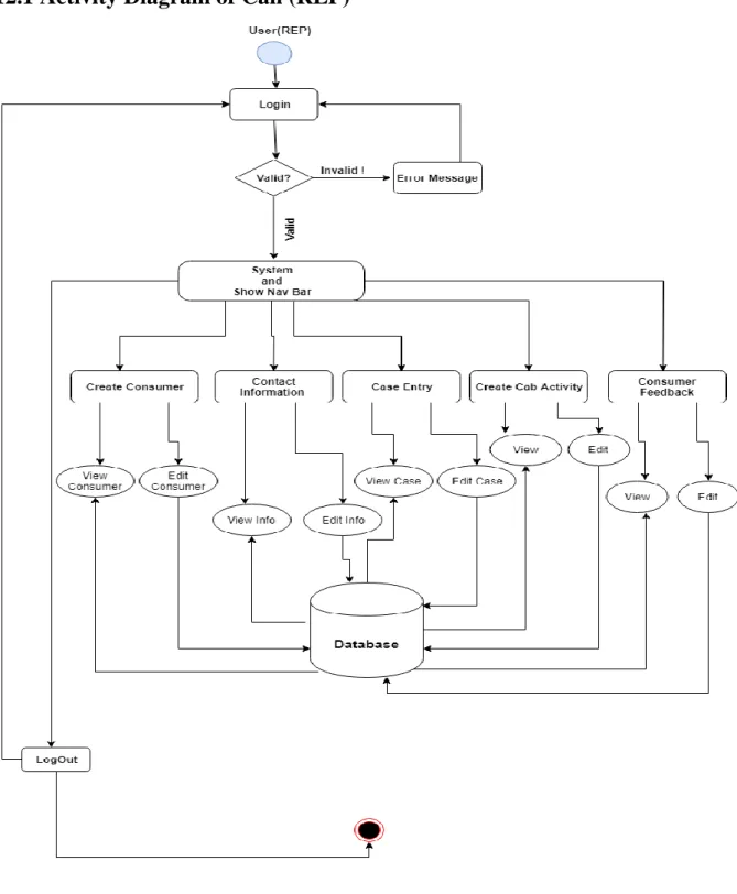
12.1 Activity Diagram of Call (REP)
Fig: 12.1 Activity Diagram of Call (REP)
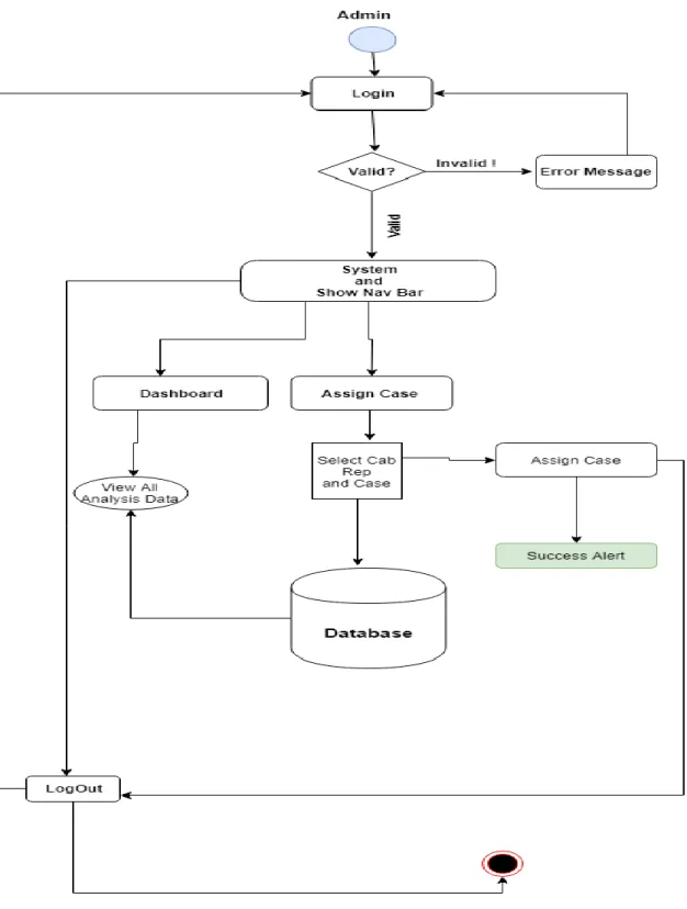
12.2 Activity Diagram of Admin
Fig: 12.1 Activity Diagram of Admin
12.3 Activity Diagram of CAB Representative
Fig: 12.3 Activity Diagram of CAB Representative
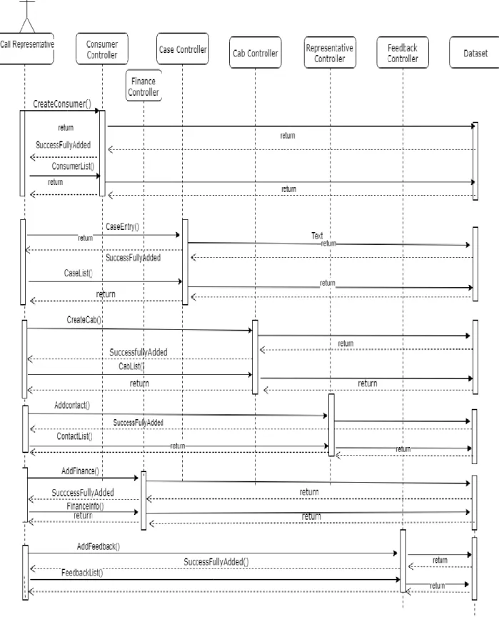
Chapter 13: Sequence Diagram 13.1 Sequence Diagram of Call Representative
Fig: 13.1 Sequence Diagram of Call Representative
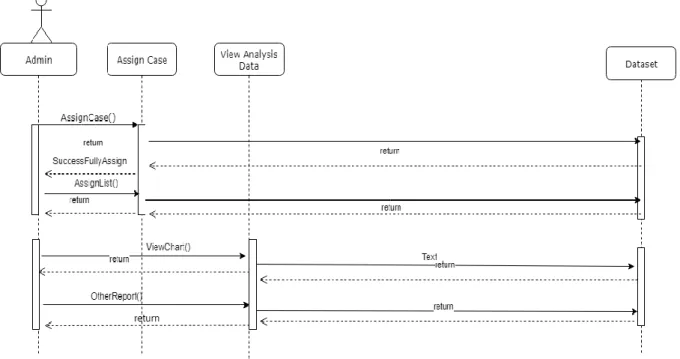
13.2 Sequence Diagram of Admin
Fig: 13.2 Sequence Diagram of Admin
13.3 Sequence Diagram of CAB Representative
Fig: 13.3 Sequence Diagram of CAB Representative
Chapter 14: Data Flow Diagram 14.1 Context Diagram
Fig: 14.1 Sequence Diagram of Call Representative
Chapter 15: Use Case Diagrams 15.1 Use Case Diagram of User Authentication
Fig: 13.2 Use Case Diagram of User Authentication
Table: 1.0 Use Case Description
15.2 Use Case Diagram of Admin
Fig: 15.2 Use Case Diagram of Admin
Use Case No. 1.0
Use Case Name View All Report
Actor Admin
Description Admin can view all the report of cases
Precondition Login
Trigger Click Data List
Table: 1.0 Use Case Description
Use Case No. 2.0
Use Case Name Dashboard
Actor Admin
Description Admin get access Dashboard to see
analytical bar chart
Precondition Login
Trigger Click Dashboard Manu
Use Case No. 3.0
Use Case Name Assign cases
Actor Admin
Description Assign case to the Cab Representative
Precondition Login as a admin
Trigger Click Assign case Manu
Table: 2.0 Use Case Description
Table: 3.0 Use Case Description
15.3 Use Case Diagram of Call Representative
Fig: 15.3 Use Case Diagram of Call Representative Table: 1.0 Use Case Description
Use Case No. 1.0
Use Case Name Create Consumer
Actor Call Representative
Description Call Representative can create consumer
Precondition Login
Trigger Click Create Consumer
Use Case No. 2.0
Use Case Name Consumer view/Edit
Actor Call Representative
Description Call Representative can view/edit data
Precondition Login
Trigger Click Consumer List
Use Case No. 3.0
Use Case Name Case Entry
Actor Call Representative
Description Call Representative can add new cases
Precondition Login
Trigger Click Create Case
Table: 2.0 Use Case Description
Table: 3.0 Use Case Description
Table: 4.0 Use Case Description
Use Case No. 4.0
Use Case Name Case view
Actor Call Representative
Description Call Representative can view cases detail
Precondition Login
Trigger Click Case list
Use Case No. 5.0
Use Case Name Create Cab Activity
Actor Call Representative
Description Call Representative can Create Cab Activity
Precondition Login
Trigger Click Create Cab Activity
Use Case No. 6.0
Use Case Name Cab Activity view/edit
Actor Call Representative
Table: 5.0 Use Case Description
Description Call Representative view all Cab Activity and Edit
Precondition Login
Trigger Click Cab Activity List
Use Case No. 7.0
Use Case Name Financial data add
Actor Call Representative
Description Call Representative Can add Financial data
Precondition Login
Trigger Click Add Financial Data
Use Case No. 8.0
Use Case Name Financial data view/Edit
Actor Call Representative
Description Call Representative Can view/edit Financial
data
Precondition Login
Table: 6.0 Use Case Description
Table: 7.0 Use Case Description
Table: 8.0 Use Case Description
Trigger Click Cab Activity List
Use Case No. 9.0
Use Case Name Contact Information Create
Actor Call Representative
Description Call Representative Can Create their contact
info and also Cab representative info
Precondition Login
Trigger Click Contact Information
Use Case No. 10
Use Case Name Contact Information View/Edit
Actor Call Representative
Description Call Representative Can View/Edit their
contact info and also Cab representative info
Precondition Login
Trigger Click Contact Information List
Table: 9.0 Use Case Description
Table: 10 Use Case Description
15.4 Use Case Diagram of CAB Representative
Use Case No. 11
Use Case Name Consumer Feedback
Actor Call Representative
Description Call Representative Can add the feedback of
Consumer
Precondition Login
Trigger Click Consumer Feedback
Use Case No. 12
Use Case Name Consumer Feedback
Actor Call Representative
Description Call Representative Can add the feedback of
Consumer
Precondition Login
Trigger Click Consumer Feedback
Table: 11.0 Use Case Description
Table: 12 Use Case Description
Fig: 15.4 Use Case Diagram of CAB Representative
Use Case No. 1.0
Use Case Name View assign case
Actor CAB Representative
Description CAB Representative Can see their assign
case
Precondition Login
Trigger Assign Case
Use Case No. 2.0
Use Case Name Review Case
Table: 1.0 Use Case Description
16. ER Diagram
Actor CAB Representative
Description Call Representative Can review case
Precondition Login
Trigger Review Case
Table: 2.0 Use Case Description
Fig: ER Diagram
17. Class Diagram
Fig: Class Diagram
18. Model Class Diagram
Fig: 18.1 Model Class Diagram
Fig: 18.2 Model Class Diagram
19.0 User Interface and Manuals 19.1 User Login
19.2 Admin Dashboard
19.2.1 Admin Case Assign to CAB Officer
19.3 Call Representative UI 19.3.1 Create Consumer
19.3.1 Consumer List
19.4 Case Entry
19.4.1 Case List
19.7 Create Cab Activity
19.8 Consumer Feedback
19.9 List of Consumer Feedback
19.10 Contact Information
19.11 Contact Information List
19.12 Call Representative send email to consumer
19.12.1 View email
19.13 CAB Officer Assign Case List
19.14 CAB Feedback UI
Chapter 20: User Manual
User must have to register to the site then he/she will get access by login
If user role is a admin then he can access the char view, he can see the all report, if he want to assign case to any CAB officer then he\she have to click on the assign case Manu then fill the all required field.
If user role is a CAB officer, he/she can view his/her assign case list and case details.
After case resolution, he/she can give his feedback about assign case. But he/she will not able to see his feedback report
If user role is a Call representative then he/she can give data entry to the site and send an email confirmation to the consumer.
20.1 Reference:
[1] https://stackoverflow.com [2] https://www.google.com/
[3] https://codepen.io/pens/
[4] https://www.c-sharpcorner.com
Chapter 21: Conclusion
The Consumer Complain Tracking System (CCTS) is storing all the consumer data and all the cases information. Easily consumer can complain about his/her problem. The call Representative (REP) can access to the system and easily he can entry all the needed data. This system also Provide a set of Analysis of data such as cases, area number of cases etc.
This system is supposed to run as a pilot project here in CAB for a few months to get the user acceptance and more feasibility. After the feedback and requirements, the system will go for fine tuning and hope within 3-4 months it will run smoothly in CAB while the consumer our country beneficiaries of this project.