Dynamic Modelling of a Flexible Manipulator:
Comparison between AMM and FEM
M. Khairudin
* #Department of Electrical Engineering Education Yogyakarta State University,Yogyakarta, Indonesia
Abstract — This paper presents the dynamic modelling of a
flexible robot manipulator incorporating payload. A planar flexible manipulator incorporating structural damping, hub inertia and payload that moves in the horizontal plane is considered. A dynamic model of the system is developed using a finite element and assumed mode methods (FEM and AMM). In this work will make a comparison between FEM and AMM. Simulation is performed to assess the dynamic model and system responses at the hub and modal displacement of link are presented and analysed in time and frequency domains. Moreover, effects of payload on the dynamic characteristics of the flexible manipulator are studied and discussed
Key words - Assumed mode, finite element, modelling, flexible manipulator.
I. INTRODUCTION
Flexible manipulators are used in a wide spectrum of applications starting from simple pick and place operations of an industrial robot to micro-surgery, maintenance of nuclear plants and space robotics [1]. However, the control of flexible manipulators to maintain accurate positioning is extremely challenging.
These Problems arise due to lack of sensing, vibration due to system flexibility, imprecise positional accuracy and the difficulty in obtaining accurate model for the system [2]. Moreover, the complexity of this problem increases when the flexible manipulator carries a payload. Practically, a robot is required to perform a single or sequential task such as to pick up a payload, move to a specified location or along a pre-planned trajectory and place the payload. The dynamic behaviour of the manipulator is significantly affected by payload variations [3]. If the advantages associated with lightness are not to be sacrificed, accurate models and efficient controllers have to be developed.
The objective of the modelling of a flexible manipulator is to achieve an accurate model representing the actual system behaviour. It is important to recognise the flexible nature and dynamic characteristics of the system and construct a suitable mathematical framework. Modelling of a single-link flexible manipulator has been widely established. Various approaches have been developed which can mainly be divided into two categories: the numerical analysis approach and the assumed mode method (AMM). The numerical analysis methods that are utilised include finite difference and finite element
methods. Both approaches have been used in obtaining the dynamic characterisation of single-link flexible manipulator systems incorporating damping, hub inertia and payload [4]. Performance investigations of both techniques in modelling of flexible manipulators have shown that the finite element method (FEM) can be used to obtain a good representation of the system [3].
Transition This paper presents comparison between AMM and FEM for the dynamic modelling and characterisation of a flexible robot manipulator. It can be shown that modelling and characterisation of the system has not been adequately addressed in the literature. For the system, the effects of other physical parameters such as payload on the dynamic characteristics of the system should be further explored. In this work, a flexible manipulator incorporating structural damping, hub inertia and payload that moves in the horizontal plane is considered. The payloads are attached at the end-point of the link whereas hub inertias are considered at the actuator joints. Comparison between AMM and FEM are used to derive the dynamic model of the system. Simulation of the dynamic model is performed in Matlab and Simulink. System responses namely angular position, modal displacement, and the fast fourier transform (FFT) of the modal displacements are evaluated in both time and frequency domains. Moreover, the works presents the effects of varying payload on the dynamic characteristics of the system. The work presented forms the basis of design and development of suitable control strategies for a flexible link manipulator systems.
II.MODELLING OF THE FLEXIBLE MANIPULATOR SYSTEM A. The Flexible Manipulator
This section describes the flexible manipulator system used in this study. The structure of a flexible manipulator system is shown in Figure 1. The links are cascaded in a serial fashion and are actuated by rotors and hubs with individual motors.
The link has length
l
with uniform mass density per unit lengthU
. The link is clamped at the rotor of the motor. E andI represent Young modulus and area moment of inertia of both links respectively. A payload is attached at the end-point of link. X0Y0 is the inertial co-ordinate frame XY is the rigid body
coordinate frame associated with the ith link and
X
Y
is the moving coordinate frame.T
is the angular positions andPage 185 of 436
)
,
(
x
t
v
is the transverse component of the displacement vector.M
p is an inertial payload mass with inertiaI
p atthe end-point of link.
Fig 1. Structure of a flexible manipulator.
The physical parameters of the flexible manipulator system considered in this study are shown in Table 1. Jhis the
inertia of the motor and hub. The input torque, τ(t) is applied at each motor and G is the gear ratio for the motor.
TABLE I
PARAMETERS OF A FLEXIBLE MANIPULATOR Symbol Parameter Size Unit ML1, ML2 Mass of link 0.05 kg
ρ Mass density 2684.56 kgm-1
EI Flexural rigidity 597.87 Nm2
Jh Motor and hub inertia 0.60 x10⁻³ kgm2
Mp Payload mass max 0.1 kg
Ip Payload inertia max 0.05 x 10⁻³ kgm2
l Length of link 0.5 m Width of link 0.025 m Thickness of link 1.49 x10⁻³ m Jo Moment of inertia 3.125 x10⁻³ kgm2
B. AMM and FEM Modelling
This section presents a comparison between AMM and FEM methods for the development of dynamic behaviour of the flexible manipulator system. For the FEM modelling refers to [3] with parameters modified. Otherwise, kinematics and dynamics equation of motion is briefly discussed. The description of kinematics is developed for a chain of serially connected flexible link to derive the dynamic model using AMM refers to [5] and [6] with parameters modified. Otherwise for FEM method refer to [3]. Comparison between AMM and FEM for flexible multilink manipulator have been invetigated [7].
To derive the dynamic equations of motion of flexible manipulator, the total energies associated with the manipulator system needs to be computed using the kinematics formulations. The formula for AMM in this study refer to [8]. The total kinetic energy of the manipulator, where TR, TL and TPL are the kinetic energies associated with the rotors, links
and the hubs, respectively, is given by
T
T
RT
LT
PL (1) As shown in Figure 1 and the kinematics formulation described previously, the kinetic energy associated with the payload where 1 11(
k)
n k k n
j j
n
¦
¦
l
c
:
T
X
; n being the link number, prime and dot represent the first derivatives with respect to spatial variable x and time, respectively can be written as
2 n n n P 1 n T
1 n p
PL I ( (l ))
2 1 p p M 2 1
T : Xc (2)
The total potential energy of the system due to the
deformation of the link by neglecting the effects of the gravity can be written as
i 2 2 i
i i 2 l
0 i n
i
dx dx
) x ( d ) EI ( 2 1
U i
¸ ¸ ¹ · ¨
¨ © § ³
¦ X (3) The dynamics of the link at an arbitrary spatial point x
along the link at an instant of time t can be written using Euler-Beam theory as
(
)
(
,
)
(
2,
)
0
2
4 4
w
w
w
w
t
t
x
x
t
x
EI
i i ii i i i
X
U
X
(4) On the other hand, bending deflections
X
i(
x
i,
t
)
can be expressed as a superposition of mode-shapes and time dependent modal displacements as
¦
m
n
j
ij i ij i
i
x
t
x
q
t
1
)
(
)
(
)
,
(
I
X
(5)where
q
ij(
t
)
andI
ij(
x
i)
are the jth modal displacement andjth mode shape function for the ith link. The solution of equation (5) is in the form of
))] x sinh( ) x (sin(
x cosh( ) x [cos( N ) x (
i ij i
ij ij
i ij i
ij ij
i ij
E E
J
E E
I
(6)
where
J
ij is given as
) sinh (sin
M cosh cos
) cosh (cos
M sinh sin
ij ij
i ij L ij ij
ij ij
i ij L ij ij
ij
i i
E E
U E E
E
E E
U E E
E J
(7)
and
E
ij is the solution of the following equation :θ1
Y0
Yi
Link
Xi
Payload
X0
Page 186 of 436
0 ) l cosh l cos 1 (
J M ) l sinh l cos
l cosh l (sin J
) l sinh l cos
l cosh l (sin M
l cos l cosh 1
i ij i
ij
2 i
4 ij L L i ij i ij
ij i
ij i
3 ij L i ij i ij
i ij ij
i ij L i ij i ij
i i
i i
E
E U
E E
E
E E
U E E
E
E E
U E E
E
(8)
Subsequently, the natural frequency for the jth mode and
ith link,
Z
ij, is determined from the following expression:
i i ij
ij
EI
U
E
Z
2(
)
(9) In this work, the dynamic model of the system incorporating
payload is investigated.
IV.RESULTS AND DISCUSSION
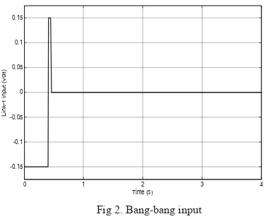
To demonstrate the effects of payload on the dynamic characteristics of the system, various payloads of up to 0.1 kg were examined. Figure 1 presents the bang-bang input of + 0.15 rad for the system.
0 1 2 3 4
-0.15 -0.1 -0.05 0 0.05 0.1 0.15
Time (s)
L
in
k
-1
i
n
p
u
t
(v
o
lt
)
Fig 2. Bang-bang input
Figure 3 and 4 show the system response of the flexible manipulator with payloads of 0.05 kg and 0.1 kg respectively. It is noted that the angular positions decrease towards the positive direction with increasing payloads. For payloads of 0.05 kg and 0.1 kg, the steady-state angular position levels for link-1 were obtained as 0.31 rad and 0.28 rad respectively. It is more similar steady state position levels between AMM and FEM.
The time response specifications of angular positions have shown significant changes with the variations of payloads both AMM and FEM. It is noted that the settling times for both links increases with increasing payload. However, with increasing payload, the system exhibit higher overshoot for both links. For AMM, the response exhibits an overshoot of 2.89 % with the settling time of 1.04 s and an overshoot of 3.28 % with the settling time of 1.08 s for 0.05
kg and 0.1 kg respectively. Thus, a more overshoot as compared to the case of 0.1 kg payload was obtained. For FEM, percentage overshoots of 0.77 % with the settling time of 0.85 s and an overshoot of 0.95 % was achieved with the settling time of 0.90 s.
0 1 2 3 4
0 0.1 0.2 0.3 0.4 0.5
Time (s)
L
in
k
p
o
s
it
io
n
(
ra
d
)
AMM FEM
Fig 3. Link position with of 0.05 kg payload
0 1 2 3 4
0 0.1 0.2 0.3 0.4 0.5
Time (s)
L
in
k
p
o
s
it
io
n
(
ra
d
)
AMM FEM
Fig 4. Link position with of 0.1 kg payload
Figures 5 and 6 show modal displacements responses of the system with payloads respectively. It is noted with increasing payloads, the magnitudes of vibration of modal displacement increase for both methods. Using AMM, the maximum modal displacement responses of 6.12 mm and 8.76 mm for 0.05 kg and 0.1 kg payload respectively. On the others hand, the magnitude of the modal displacement responses increase with increasing payloads. For FEM the responses of 8.83 mm and 11.03 mm for 0.05 kg and 0.1 kg payload respectively.
Page 187 of 436
0 1 2 3 4 -12
-8 -4 0 4 8 12
Time (s)
Mo
d
a
l
d
is
p
la
c
e
me
n
t
(mm)
AMM FEM
Fig 5. Displacement of the system with 0.05 kg payload
0 1 2 3 4
-12 -4
-8 0 4 8 12
Time (s)
M
o
d
a
l
d
is
p
la
c
e
m
e
n
t
(m
m
)
AMM FEM
Fig 6. Displacement of the system with 0.1 kg payload
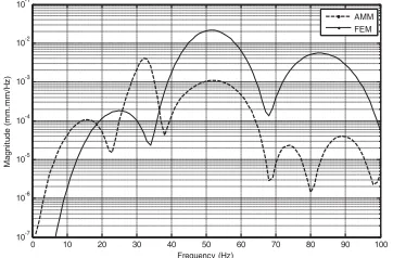
In this work, First Fourier Transform (FFT) of the modal displacement response is utilised to investigate the effects of payload on the dynamic behaviour of the system in the frequency domain. Figure 7 and 8 show the FFT of the modal displacement response with payloads of 0.05 kg and 0.1 kg. It is noted that the resonance modes of vibration of the system shifts to lower frequencies with increasing payloads for both methods. For a payload between 0.05 kg and 0.1 kg the resonance frequencies for AMM shifted from 32 Hz, 54 and 89 Hz to 18 Hz, 54 and 82 Hz. On the other hand, the resonance frequencies using FEM shifted from 27 Hz, 53 and 89 Hz to 25 Hz, 52 and 83 Hz for the first, second and third modes of vibration respectively.
0 10 20 30 40 50 60 70 80 90 100 10-7
10-6 10-5 10-4 10-3 10-2 10-1
Frequency (Hz)
M
a
g
n
it
u
d
e
(
m
m
.m
m
/H
z
)
AMM FEM
Fig 7. FFT of displacement of the system with 0.05 kg payload
0 10 20 30 40 50 60 70 80 90 100 10-7
10-6 10-5 10-4 10-3 10-2 10-1
Frequency (Hz)
M
a
g
n
it
u
d
e
(
m
m
.m
m
)/
H
z
)
AMM FEM
Fig 8. FFT of displacement of the system with 0.1 kg payload
V.CONCLUSION
The development of dynamic model of a flexible manipulator incorporating payload has been presented. The model has been developed using a comparison between AMM and FEM approach. Simulations of the dynamic model have been carried out in the time and frequency domains where the system responses including angular positions and modal displacements are studied. It is found that the payload significantly affected the system behaviour. These results are very helpful and important in the development of effective control algorithms for a flexible robot manipulator incorporating payload.
REFERENCES
[1] Dwivedy, S.K. Eberhard, P, “Dynamic analysis of flexible manipulators, a literature review,” Jurnal on Mechanism and Machine Theory 41. (2006) 749–777.
[2] Martins J.M., Mohammed Z., Tokhi M.O., Sa’da Costa J.and Botto M.A, “Approaches for dynamic modeling of flexible manipulator systems,” IEE Proc-Control Theory Appl., (2003). Vol 150, No.4, July 2003. [3] Tokhi MO, Mohamed Z, Shaheed MH, “Dynamic characterization of a
flexible manipulator system,” Robotica, (2001), 19:571-580.
[4] Tokhi MO, Mohamed Z, Azad AKM, “Finite difference and finite element approaches to dynamic modelling of a flexible manipulator,” Proceeding of IMechE-I: Journal of Systems and Control Engineering, (1997); 211:145-156.
[5] De Luca A., Siciliano B., “Closed-form dynamic model of planar multi-link lightweight robots,” IEEE Transactions on Systems, Man, and Cybernetics 21 (4). (1991). 826-839.
[6] Subudhi B, Morris AS. Dynamic, “Modelling, Simulation and Control of a manipulator with flexible links and joints,” Robotics and Autonomous System, (2002) 41:257-270.
[7] R. J. Theodore, "Comparison of the Assumed Modes and Finite Element Models for Flexible Multilink Manipulators," The International Journal of Robotics Research, vol. 14 no. 2 91-111, 1995.
[8] M. Khairudin, Z. Mohamed, A.R. Husain, R. Mamat, “Dynamic characterisation of a two-link flexible manipulator: theory and experiments”, International Journal of Advances in Robotic Research, Vol. 1 (1), 2014.