UNIVERSITI TEKNIKAL MALAYSIA MELAKA
POTENTIAL STUDY OF PIEZOELECTRICITY GENERATION
SYSTEM FROM VEHICLE VIBRATION
This report submitted in accordance with requirement of the Universiti Teknikal Malaysia Melaka (UTeM) for the Bachelor Degree of Electrical Engineering
Technology (Industial Power) (Hons.)
by
STEVEN ANAK HARRY B071210335
890915-13-5673
i
DECLARATION
I hereby, declared this report entitled “Potential Study of Piezoelectricity Generation System from Vehicle Vibration” is the results of my own research except as cited in
references.
Signature : ... Author’s Name: Steven Anak Harry
ii
APPROVAL
This report is submitted to the Faculty of Engineering Technology of UTeM as a partial fulfilment of the requirements for the Degree of Bachelor of Electrical Engineering Technology (Industrial Power) (Hons.). The member of supervisory is as follow:
... Syahrul Hisyam bin Mohammad @ Abd Rahman
iii
ABSTRACT
iv
DEDICATION
I dedicate my dissertation to my family and many friends. A special feeling of gratitude to my be loving parents whose give me endless support throughout my studies and to my family whose never left me alone and are very important to me.
v
ACKNOWLEDGEMENT
Firstly, most thanks to Jesus Christ for giving me the opportunity to complete this Final Year Project report with a huge success after I went through a lot of obstacles with love, hope, faith and patience. I would also like to thank my parents for encouraging me throughout all the heavy situations I am facing and keep supporting on my financial. I would not be in this university and not be able do my degree project without their permission and blessing.
Not to forget, I would like to thank my supervisor, Mr. Syahrul Hisyam bin Mohammad @ Abd Rahman for guiding me in completing this project and report. He has taught me a lot of useful things and knowledge not only in theoretical but also practical. Furthermore, thanks to all lecturers and technicians that has guided me to get a good knowledge’s and experiences either in the class or in the lab session. Besides, I would also like to thank all of my fellow friends including my friends under the same supervisor, Nur Mohd Haniff, Nor Shazana and Mohd. Ridzuan for sharing their opinions regarding this project.
vi
2.1 History of Piezoelectric 4
2.2 Piezoelectric Effect 6
2.3 Piezoelectric Materials 7
2.4 Energy Harvesting From Vibration Absorber (EHVA) 8
2.5 Piezo Bending Actuator 10
2.6 Piezoelectric Bending Type 11
2.6.1 Piezoelectric Ceramic EB-T-320 11
2.6.2 Piezoelectric LDT0-028K 13
vii
2.7 Mechanical Vibration 17
2.8 Vibration Measurement 18
CHAPTER 3: METHODOLOGY 21
3.1 Method of Research 21
3.2 Piezoelectric Circuit Design 24
3.2.1 Diode Bridge Rectifier 25
3.3 Diode Bridge Rectifier Software Design 25
3.4 Diode Bridge Rectifier Hardware Design 27
3.5 Vibration Test 28
3.6 Choosing Piezoelectric 30
3.7 Conclusion 31
CHAPTER 4: RESULT AND DISCUSSION 32
4.1 Introduction 32
4.5 Vibration Graph Analysis 40
4.6 Piezoelectric Generator Data 40
4.6.1 Part A Piezoelectric Generator Result 41
4.6.2 Part B Piezoelectric Generator Result 43
4.7 Piezoelectric Generator Road Test 45
CHAPTER 5: CONCLUSION AND FUTURE WORK 47
5.1 Introduction 47
5.2 Conclusion 47
viii
REFERENCES 49
LIST OF TABLES
2.1 Piezoelectric ceramic EB-T-320 technical specification 12 2.2 Piezoelectric LDT0-028K technical specification 14 2.3 Piezoelectric Q220-A4-203YB (Quick Mount) technical specification 15 2.4 Piezoelectric EH220-A4-503YB technical specification 17
3.1 Diode bridge rectifier performance 25
3.2 Operating frequency for each of piezo film model 30
4.1 Vibration test result at Part A 34
4.2 Vibration test result at Part B 34
4.3 Vibration test result at Part C 34
4.4 Voltage generated from piezoelectric generator at Part A 42 4.5 Voltage generated from piezoelectric generator at Part B 44
ix
LIST OF FIGURES
2.1 Langevin’s sandwich 5
2.2 Piezoelectric produced electricity when stress is applied 6
2.3 EHVA design 9
2.4 The EHVA is mounted at rear door 9
2.5 Piezoelectric bending actuator structures 10
2.6 Piezoelectric ceramic EB-T-320 11
2.7 Piezoelectric ceramic EB-T-320 dimension 12
2.8 Piezoelectric LDT0-028K 13
2.9 Piezoelectric LDT0-028K dimension 13
2.10 Piezoelectric Q220-A4-203YB (Quick Mount) 14
2.11 Piezoelectric Q220-A4-203YB (Quick Mount) dimension 15 2.12 Piezoelectric EH220-A4-503YB (Double Quick Mount) 16
2.13 Piezoelectric EH220-A4-503YB dimension 16
2.14 Pendulum swings illustrates the vibration system 18
2.15 Equations for sinusoidal motion 19
2.16 Sinusoidal relationship between displacement, velocity 20 And acceleration at 20Hz
3.1 The flow-chart of the project 22
3.2 Piezoelectric block diagram circuit design 23
3.3 Diode bridge rectifier 24
3.4 Diode bridge rectifier input and output waveform 24
3.5 Diode bridge rectifier voltage and current output waveform 25 waveforms
3.6 Process flows of diode bridge rectifier constructions 26 3.7 Piezoelectric diode bridge rectifier software design 26 3.8 Process flows of the diode bridge rectifier hardware design 27
3.9 Diode bridge rectifiers 28
x
3.11 Vibration meter model 407860 29
4.1 Initial vibration tests on Perodua Kenari 33
4.2 Engine area that produce highest vibration rate 33 4.3 Rotation per minute versus acceleration Part A graph 35 4.4 Rotation per minute versus velocity Part A graph 35 4.5 Rotation per minute versus displacement Part A graph 36 4.6 Rotation per minute versus frequency Part A graph 36 4.7 Rotation per minute versus acceleration Part B graph 37 4.8 Rotation per minute versus velocity Part B graph 37 4.9 Rotation per minute versus displacement Part B graph 37 4.10 Rotation per minute versus frequency Part B graph 38 4.11 Rotation per minute versus acceleration Part C graph 38 4.12 Rotation per minute versus velocity Part C graph 39 4.13 Rotation per minute versus displacement Part C graph 39 4.14 Rotation per minute versus frequency Part C graph 39 4.15 Voltage generated from piezoelectric at Part A 41
4.16 Piezoelectric generator is mounting at Part A 41
4.17 Piezoelectric generator is mounting at Part A 42
4.18 Piezoelectric generator is mounting at Part B 43 4.19 Piezoelectric generator is mounting at Part B 43 4.20 Voltage generated from piezoelectric at Part B 44
1
CHAPTER 1
INTRODUCTION
1.1 Introduction
Sustainable energy is an energy that can be can be produce without destroying or causing harmful to the nature. This energy also has the unlimited sources which could potentially persist into the future. This sustainable energy is also known as green energy. Today, we can see that the energy consumption around the world is increasing due to a massive development around the world including vehicle industries. The usages of fuels are also increases as the demand from the people to have their own vehicle are increase. Nowadays, green energy became so popular especially to the countries that were still developing around the world. Green energy are renewable energy resources that actually came from sunlight, wind, rain, tides, plants and more. Compare to fossil fuels, it does take a millions of years to develop into a fine fuel and at the same it also a finite sources of energy.
2
1.2 Problem Statement
Electrical motor vehicles are the type of vehicles that are using battery as their energy sources to move the vehicle. This type of vehicle is good as it reduce the carbon emission in the compared to a fuel vehicle used on the road. It also does not make a loud sound as a normal vehicle do. Some of this vehicle are fully operated using battery but some of it are using both battery and fuel. The battery must be charging every time it run out of power, thus this indicates that the battery has a certain limited of usage. Besides, to replace a battery if the battery is damage is quite expensive and this battery also has a short lifespan.
Since that most of population in the world are having their own vehicle, there are abundant alternative methods to generate energy from the vehicle. As we can see when the car is igniting, the vehicle will produce some sort of vibration. This vibration can be used as an energy harvester. Harvesting electrical energy from vibration is of great interest, particularly for generating voltage, due to the ubiquitous presence of environmental motion that can be transformed into useful electrical power through several methods of electromechanical transduction.
3
1.3 Project Objective
The objectives of this research study are listed as follows:
a) To study the potential of a piezoelectric as an energy harvesting from vehicle.
b) To develop and testing a piezoelectric energy harvesting system from vehicle.
c) To analyse a small voltage from vehicle vibration by using piezoelectric.
1.4 Project Scope
In order to achieve the stated objectives, several work scopes had been identified. This scope is to make sure that this project is not out of the studies and investigation that will be conduct. The work scopes are listed as below:
a) To identify the sources of vibration on selected vehicle. b) To measure the vibration value on the vehicle.
c) To compare and select the suitable piezoelectric to generate electricity through vehicle vibration.
4
CHAPTER 2
LITERATURE VIEW
This chapter provides the preliminary reviews for the piezoelectric background. Literature reviews will explain about the history of the piezoelectric and type of materials that are used in manufacturing this project. Besides, the discussion about the piezoelectric that will be used in this project will be listed out and explain. Hence, this chapter will start with the explanation of the history of the piezoelectric in the next section.
2.1 History of Piezoelectric
In 1880, Jacques and Pierre Curie were working as a researcher in the mineralogy laboratory at Sorbonne, Paris in France. Both of them demonstrated that when crystal of quartz is applied with stress in form of weight, a proportional electrostatic polarisation was generated along an axis at an angle to the direction of the stress to a sufficient magnitude that the charge on the surface could be detected by an electrometer. This phenomenon was called piezoelectricity which is taken from the Greek word which means pressure. This phenomenon has the similar to Lenz’s law, which the existence for this inverse effect has to do with induced current and magnetic field.
5
Figure 2.1 Langevin’s sandwich
In 1920’s the quartz material that are functions for the oscillators stabilization were now becoming as a field of frequency control. This make the quartz resonator become more precise in any applications especially in we known as a timekeeping. Thus, this make the frequency become the most entity known that we are used to know today. There are a lot of applications that used the piezoelectric such as telephone speakers, sonar arrays, mechanical actuations and even sensing microstructures which can be implement into electronic chips.
Arthur Ballato (2001) stated that the piezoelectric cantilever bimorph consist of two layer laminate which are silicon with thin patches. This patch contains active film materials such as aluminium nitride or zinc oxide that can drive the piezoelectric patches into flexural motion. This bending mode delivers the greatest possible displacement for generating voltage. The bimorph Micro-Electro-Mechanical-Systems (MEMS) devices provide otherwise unavailable capabilities and require piezoelectricity as the transduction mechanism. An alternative configuration for the piezoelectric are laminated plate, where aluminium nitride or zinc oxide thin-film layers drive silicon plates in resonant thickness modes for integrated frequency control devices.
6
2.2 Piezoelectric Effect
Piezoelectric Effect is the ability of certain materials to generate an electric charge in response to applied mechanical stress. The words Piezoelectric were actually derived from the Greek language, piezein, which means to squeeze or press, which is Greek for “push”. One of the unique characteristics of the piezoelectric effect is that it is reversible, meaning that materials exhibiting the direct piezoelectric effect (the generation of electricity when stress is applied) also exhibit the converse piezoelectric effect (the generation of stress when an electric field is applied). When piezoelectric material is placed under mechanical stress, a change in positive and negative charge centres in the material takes place, which then resulting the external electrical field. But when it is reversed, an outer electrical field will either stretches or compresses the piezoelectric material.
Figure 2.2 Piezoelectric produced electricity when stress is applied
Antoine Ledoux (2011) stated that the piezoelectric creates a voltage is because when the mechanical stress is applied, the crystalline structure is disturbed and it changes the direction of the polarization of the electric dipoles. In order for the material to be polarized, it is exposed to a strong direct current electric field whose goal is to align all dipoles in the material. He also stated that as the mechanical stress increase, the bigger the change in polarization and the more electricity is produced.
7
through the load will stop the moment the squeezing is stopped. This basically can be called a DC. The DC can be created only for a moment because the piezoelectric crystal cannot be indefinitely compressed to keep the current flowing in one direction because of the compression that would destroy it. In other hand, the AC is produced when the piezoelectric crystal being compressed and released alternately which may leads the current to flow in both direction. Basically, the output of a piezoelectric crystal is an alternating signal and must be converted first into digital signal to use the voltage for low power consuming electronic devices (Dikshit et al, 2010).
2.3 Piezoelectric Materials
There are many types of piezoelectric that can be used to build a piezoelectric that can react when the mechanical stress is applied. These materials might be different but it has the same functions. Satoru Fujishima (2000) said that Rochelle salt was used for underwater tranducers and phonograph pickups while barium titanate is used for communications devices, underwater transducers and dielectric components such as capacitors. Meanwhile quartz crystal was used for underwater transducers during World War I. During 1954, PZT ceramics is discovers and by that time all the piezoelectric applications that used barium titanate ceramics are being replaced. But the most commonly known piezoelectric material is quartz. According to Antoine Ledoux (2011) the most commonly use materials piezoelectric are:
a) Quartz (SiO2)
- Quartz shows a strong piezoelectricity due to its crystalline structure, meaning that when a pressure is applied on a quartz crystal an electrical polarization can be observed along the pressure direction.
b) Gallium Orthophosphate ((GaPO4)
8
important as the one for the quartz, making it is a valuable asset for mechanical application. It is not natural element, it has to be synthesised.
c) Barium Titanate (BaTiO3)
- This element is an electrical ceramics; it is usually replaced by lead zirconate titanate (PZT) for piezoelectricity. It is used for microphones and transducers.
d) Lead Zirconate Titanate (PZT)
- It is considered one of the most economical piezoelectric elements; hence it is used in a lot of applications.
e) Tourmaline
- This crystal is commonly black but can range from violet to green and pink. f) Berlinite (AlPO4)
g) Zinc Oxide
h) Aluminium Nitrade (AlN) i) Polyvinylidene Fluoride (PVDF)
2.4 Energy Harvesting From Vibration Absorber (EHVA)
9
Figure 2.3 EHVA design
The design has been tested on a city bus structural panel which is partially suspended and supported by several bolts as a safety guards for passenger that is near to the rear door. The panel is outlined by a green dash while some of the mounting bolt are indicated with the yellow arrows. Figure 2.4 shows the EHVA that is mounted ate the rear door.
10
2.5 Piezo Bending Actuator
According to Yi Pu et al. (2014) an electromechanical actuator can become the more efficient energy harvesting system, which can improving the efficiency usage of the fuel. If two piezoelectric ceramic plates are bonded together with a supporting material and counter-actuated, this results in a pronounced deformation of the composite similar to the case of a bimetal. These bending actuators are design so it can deflects for several millimetres, withstands several Newton forces and achieve short deflection times. Therefore, the piezo bending actuator is one of the highest performance and fast-reacting control element.
Due to the high speed of deflection, piezoelectric productivity is increased many times over compared to the use of electromagnets. Because of its compact design, the piezo bending actuator only required less space compare to other generating devices. Its energy requirement compared to that of the electromagnets is also considerably lower. One advantage is its high reliability - downtime periods become a rare exception. The piezo bending actuator is modifiable to suit the application and is therefore an extremely versatile control element. Figure 2.5 shows that the piezo bending actuators, where yellow is resemble its electrode, orange for piezo ceramic and purple resembles its centre vane.
11
2.6 Piezoelectric Bending Type
In this section, there are a few piezoelectric bending types which can generate electricity. One of the bending types is the piezo film types. The piezo film is a flexible, lightweight, tough plastic film which is available in a variety of thicknesses and in large areas. These piezo films do have its advantages. According to D.L. Halvorsen (1986) the advantages of piezo film includes high voltage output, high dielectric strength and mechanically strong and impact resistant. Piezo film develops a voltage (potential difference) between its upper and lower surfaces when the film is stressed. This voltage arises from generation of charge within the material. If this charge is removed by the external circuit, no further charge is generated until the stress is changed. Therefore the piezoelectric film does not produce any current, even though the voltage (with no load) may be very high.
For this project purposed, there are 3 piezoelectric films that will be review in this section. These piezoelectric films will compare based on its voltage output and tip deflections. The basic characteristic for each piezoelectric film is briefly reviewed so that it is suitable for generating the voltage from vibration.
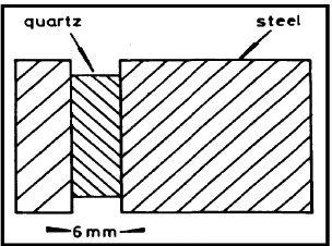
2.6.1 Piezoelectric Ceramic EB-T-320
12
This piezoelectric is a versatile piezoelectric with low power electromechanical transducer. This piezoelectric is capable of converting mechanical energy to electrical energy when the element is stressed or subjected to vibration, the, minute movement causes one layer to be under tension while the under compression. Since the two layers are polarised in opposite directions, the opposite stresses in each layer will produce an electrical output or charge. The Figure 2.7 shows the shape and dimension of this piezoelectric.
Figure 2.7 Piezoelectric ceramic EB-T-320 dimensions
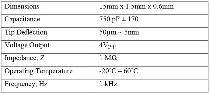
This piezoelectric has high compliance, low mass, high efficiency as well as high capacitance which mean it has low impedance. Besides having the ability to generate electricity, it also can be used as vibration or stress sensors, phonograph cartridges and micro-positioners. This piezoelectric can operate in high temperatures environment which is up to 60˚C. The Table 2.1 shows the technical specification for this piezoelectric.
Table 2.1 Piezoelectric ceramic EB-T-320 technical specification
Dimensions 15mm x 1.5mm x 0.6mm
13 2.6.2 Piezoelectric LDT0-028K
Figure 2.8 Piezoelectric LDT0-028K
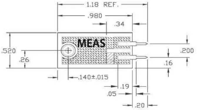
This piezoelectric is a flexible piezo film that comprises a 28μm thick piezoelectric PVDF polymer film with screen-printed Ag-ink electrodes, laminated to a 0.125 mm polyester substrate, and fitted with two crimped contacts. When this piezo film bends, it creates a high strain within the piezopolymer and as a result it generates the voltages. These device acts as a flexible "switch" when the assembly is deflected by direct contact, thus trigger MOSFET or CMOS stages directly due to sufficient generated output. The Figure 2.9 shows the added mass piezoelectric dimension.
Figure 2.9 Piezoelectric LDT0-028K dimension