AUTOMATIC RAILWAY GATE CONTROLLERUSING ZIGBEE
NURLIYANA HAZIRAH BINTI MOHD SAFEE (B021110154)
This report is submitted in partial fulfilment of requirements for the Bachelor Degree of Electronic Engineering (Wireless Communication) With Honours
Faculty of Electronic and Computer Engineering UniversitiTeknikal Malaysia Melaka
UNIVERSTI TEKNIKAL MALAYSIA MELAKA FAKULTI KEJURUTERAAN ELEKTRONIK DAN KEJURUTERAAN KOMPUTER
BORANG PENGESAHAN STATUS LAPORAN
PROJEK SARJANA MUDA II
TajukProjek : NURLIYANA HAZIRAH BINTI MOHD SAFEE
SesiPengajian : 1 3 / 1 4
Saya NURLIYANA HAZIRAH BINTI MOHD SAFEE
mengakumembenarkanLaporanProjekSarjanaMudainidisimpan di Perpustakaandengansyarat-termaktubdi dalam AKTA RAHSIA RASMI 1972)
TERHAD**
__________________________ ___________________________________
(TANDATANGAN PENULIS) (COP DAN TANDATANGAN PENYELIA)
“I hereby declare that this report entitle „Automatic Railway Gate Using ZigBee” is the result of my own work except as cited in the references. The report has not been accepted for any degree and is not concurrently submitted
in candidature of any other degree.”
Signature : ………..
Author : NURLIYANA HAZIRAH BT MOHD SAFEE
“I hereby declare that I have read this report entitle “ Automatic Railway Gate Using ZigBee” and found that it has comply the partial fulfilment for
awarding the degree of Bachelor of Electronic Engineering (Wireless communication) with Honours”
Signature : ……….……….
Supervisor‟s Name : ENGR NOOR BADARIAH BT ASAN
v
DEDICATION
vi
ACKNOWLEDGMENT
Alhamdulillah thanks to Allah S.W.T the final project is complete. I hereby would like to take this opportunity to thank all persons who has involved generously in helping me and assisting me while I was completing the PSM which is a compulsory to all UniversitiTeknikal Malaysia Melaka (UTeM) students in order to complete our degree.
I would firstly to express my deepest gratitude and thanks to my project supervisor, Madam Engr. Noor BadariahBintiAsan for his undivided support morally and physically, assistance, guidance, tolerance, which proved to be invaluable as to completion my final project.
vii
ABSTRACT
viii
ABSTRAK
ix
TABLE OF CONTENTS
CHAPTER TITLE PAGE
PROJECT TITLE i
DECLARATION STATUS OF REPORT FORM ii
DECLARATION iii
LIST OF ABBREVIATIONS xv
1 INTRODUCTION
1.0 Background of The Project 1
1.1 Problem Statement 2
1.2 Objectives 2
1.3 Scope of Project 3
1.4 Project Methodology 5
x
2 LITERATURE REVIEW
2.0 Introduction 8
2.1 Block Diagram Description 9
2.2 Previous Projects 11
2.3 Software and Theory 15
2.4 Hardware and Theory 18
3 METHODOLOGY
3.0 Review of Project Methodology 31
3.1 Introduction 31
4 RESULT AND DISCUSSION
4.0 Introduction 43
4.1 Implementation 43
4.2 Simulation Result 45
4.3 Hardware Development 46
4.4 Software Development 50
4.5 Analysis Result 62
4.6 Experimental Result 63
xi
LIST OF TABLE
TABLE TITLE PAGE
2.1 Wireless Standard 26
xii
LIST OF FIGURE
FIGURE TITLE PAGE
1.1 Scope of Project 4
1.2 Block Diagram of Project 6
2.1 Design the General Automatic Railway Gate Controller
Using ZigBee. 9
2.2 The Functionality Between Microcontroller 10
2.3 Simulation DC Motor Circuit 15
2.4 Proteus VSM 16
2.10 Voltage Regulator 23
2.11 Light Emitting Diode (LED) 23
2.12 LCD Display 24
2.13 ZigBee PRO 25
3.1 Flow Chart of Project. 35
3.2 The System Flow Chart Project. 37
3.3 The Different Soldering 39
3.4 Soldering Technique 40
xiii
3.6 Drill a Hole on PCB 42
4.1 Block Diagram of Project. 44
4.2 Schematic DC Motor Circuits 45
4.3 Schematic Power Supply Circuits. 46
4.4 Infrared Sensor Circuits 47
4.5 DC Motor Circuits 48
4.6 ZigBeeCircuits 49
4.7 LCD Display 50
4.8 Setup COM Port 51
4.9 Coordinator Test 52
4.10 Setup Modem Configuration 53
4.11 The Coordinator Set the DH and DL 54
4.12 Router Test 55
4.13 Router Terminal 56
4.14 Wireless Point-to-Point Communication 57
4.15 The Command to Reset 58
4.16 The Command to Test the LED 59
4.17 The Command When Get The Signal 60
4.18 The Command When No Signal 61
4.19 The Prototype of Automatic Railway Gate Controller Using
xiv
LIST OF ABBREVIATIONS
IEEE Institute of Electrical and Electronic Engineering WLAN Wireless Local Area Network
LED Light Emitting Diode LCD Liquid Crystal Display PCB Printed Circuit Board
V Volt
PIC Peripheral Interface Controller
Tx Transmitter
Rx Receiver
1 nowadays. This project is designed using ZigBee to prevent train accident occurred in the train door unattended. This project utilized microcontroller (PIC16F877A), two powerful IR transmitter and two receivers, one pair of transmitter and receiver is fixed up side (from where the train comes) and the other pair is fixed at down side of the train direction.
This Automatic Railway Gate Controller system was operated after signal received from the ZigBee Transmitter then the ZigBee Receiver will remain train is coming at LCD. When IR sensor detect the train, then it will send to trigger the PIC16F877A for operating the gate motor, alarm indicator and LCD display by instruction programmed.
2
1.1 Problem Statement
Nowadays, the railway gate is operating by manual operation. The railway gate management has to employ workers to be on duty for control the operation. Due to this, the worker will manually open and close the gate when the train arrived.
This project will improve the system by the automatic railway gate operation. This systemwill make improvementsto thepreviousmanual operation. Human supervision will be considered if there are problems occurred while this system was operated.
This is an idea to perform computer integration with mechanical structure to simulate what the system can do. Control system with computer applications will make the management or consumer become more effective. Therefore, this is the best example in develop railway gate management system become more efficient.
1.2 Objective
The aim of this project is to design and develop the Automatic Railway Gate Controller using ZigBee. In order to make this project successful, the objectives have been declared must be achieved in completing this project. The objectives are:
To design an Automatic Railway Gate Control by using ZigBee.
To develop a prototype of Automatic Railway Gate by using ZigBee.
3
1.3 Scope of Project
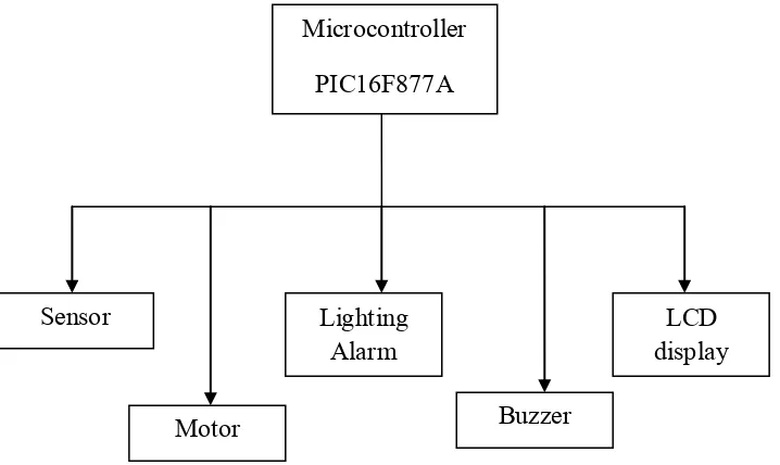
This project covered the operation of Automatic Railway Gate Controller by using ZigBee. The circuits involved such as microcontroller (PIC16F877A), power supply, IR sensor, light and buzzer, gate motor and LCD display. All of these operations will be combining to demonstrate the operation of ZigBee technology.
The operations of ZigBee works follow the instruction when ZigBee Transmitter receives the signal data from ZigBee Receiver. The combining circuits were constructed on Proteus software to seen whether that circuits was right or not. After that, the hardware part was constructed after all the simulation being done. IR sensor circuit is providing signal to triggered the PIC16F877A. The sensed signal wills active the gate motor and LCD display. The buzzer and indication light circuit was provided as additional part of this system.
4
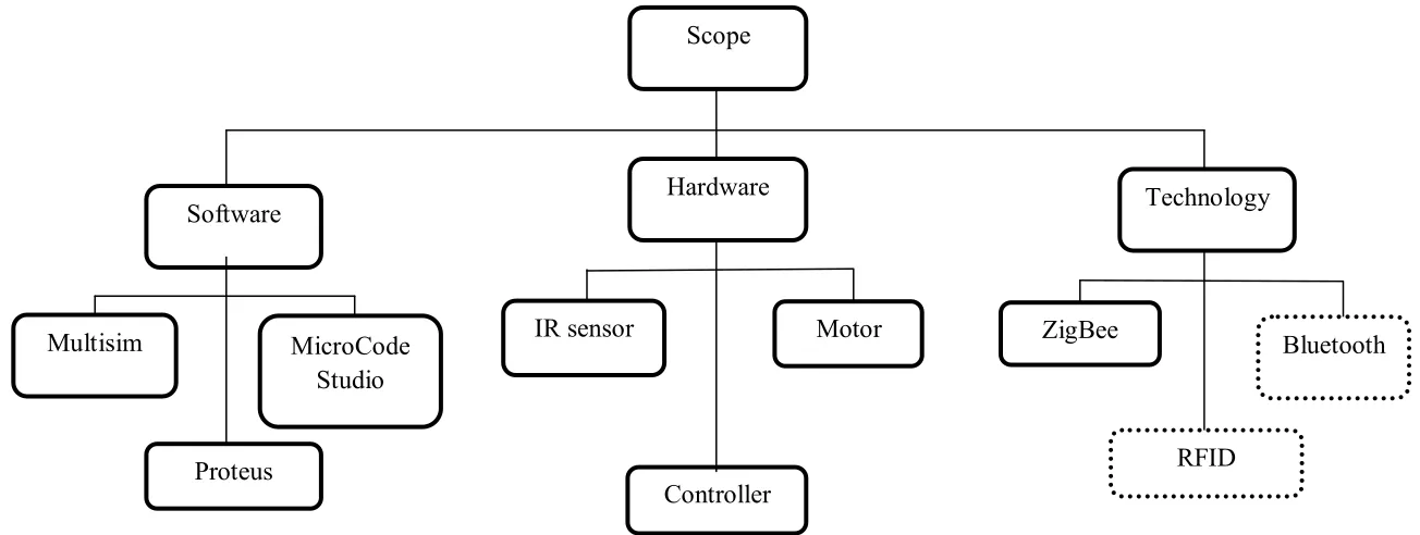
Figure 1.1: Scope of Project Scope
Software Hardware
Multisim MicroCode IR sensor
Studio
Motor
Controller Proteus
Technology
ZigBee
RFID
5
1.4 Project Methodology
6
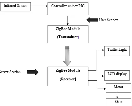
User Section
Server Section
Figure 1.2: Block Diagram of Project
The Figure 1.2 shows the block diagram of the project. The operations of ZigBee works follow the instruction when ZigBee Transmitter receives the signal data from ZigBee Receiver. The IR sensor circuit is providing signal to triggered the PIC16F877A. The sensed signal wills active the gate motor and LCD display. The buzzer and indication light circuit also active when their get the signal.
Infrared Sensor Controller unit or PIC
7
1.5 Report Structure
This report is covered by five chapters. The Chapter 1 starts with Background of the project, problem statement, objective and scope of project. The literature review is discussed in Chapter 2 and project methodology in Chapter 3. The Chapter 4 cover on hardware and software implementation. The conclusions and suggestion are respectively cover on Chapter 5.
Chapter 1: Introduction
This chapter will simply introduce about the project. This chapter contains background of project, problem statement, objective and scope of project.
Chapter 2: Literature Reviews
It will discuss about the literature review. It had review some references from previous project, journal, article, books and datasheet. All the materials were useful to ensure the success of this project.
Chapter 3: Project Methodology
This chapter will discuss the flow of this project started and how it will be functional. There are several block in flow chart to explain the process of the circuit within combining hardware and software. It also includes the analysis design, material, and method for the prototype.
Chapter 4: Result and Discussion
It will show the details of the result from testing the Automatic Railway Gate Controller Using ZigBee.
Chapter 5: Conclusion and Future Works
8
CHAPTER 2
LITERATURE REVIEW
2.0 Introduction
At present scenario, in the level crossing line the railway gate is operated usually by a gate keeper. This happen when the railway line is cross over the road and there are a gate that have to be controlled. The gate keeper work after receiving the information about the train arrival from the nearer station. When the train starts to leave the station, the particular station delivers the information to give the signal for gate keeper to get ready. This is the operation are followed for operating the railway gates [1].
10 In sequences, the gate motor will move forward direction to close the gate. It will stay closed at certain time until that has crossed the gate and reached the second sensor active the motor in backward direction so the gate will open.
Lighting signal also provided at the certain distance as pre cautionary step for driver. Meanwhile, the near station also will provide an indication alarm to remind them about the crossing train. If anything happened at the gate, this alarm will alert the station. LCD display will show the arrival of the train to cross the gate as additional features of this system.