SUPERVISOR DECLARATION
“I hereby declare that I have read this thesis and in my opinion this thesis is sufficient in terms of scope and quality for the award of the degree of Bachelor of
Mechanical Engineering (Plant and Maintenance) with honours”
Signature : ...
ii
DECLARATION
“I hereby declare that the work in this thesis is my own except for summaries and quotations which have been duly acknowledged”
Signature : ...
iii
SPECIAL THANKS TO
MOTHER AND FATHER
iv
ACKNOWLEDGEMENT
First of all, I am grateful to ALLAH S.W.T. for establishing me to complete this research and report.
I wish to express my sincere thanks to my family for their unceasing encouragement and support in all aspect.
I place on record, my sincere gratitude to my supervisor, Dr Mohd Yusoff Bin Sulaiman. I am extremely grateful and indebted to him for his expert, sincere and valuable guidance and encouragement extended to me.
I take this opportunity to record my sincere thanks to all faculty members of the Department of Plant and Maintenance, UTeM for their help and providing me with all the necessary facilities.
v
ABSTRACT
vi
ABSTRAK
vii
CHAPTER I INTRODUCTION 1
1.1 BACKGROUND 1
1.2 PROBLEM STATEMENT 2
1.3 OBJECTIVE 3
CHAPTER II LITERATURE REVIEW 4
2.1 BOILER 5
2.1.1 Fire Tube Boiler 5
2.1.2 Water Tube Boiler 5
2.2 BOILER SUPERHEATER TUBE 7
viii
CHAPTER CONTENT PAGE
2.2.2 Seamless Tube 9
2.2.3 Alloys in Super-Heater Tube Material 10
2.3 DEFINITION OF FAILURE ANALYSIS 11
2.4 BOILER SUPERHEATER TUBE LEAK OR FAILURE
13
2.4.1 Flue Gas Erosion (Outside Tube) 13 2.4.2 Pitting Corrosion or Oxygen
Corrosion (Inside Tube)
14
2.4.3 Thermal Fatigue 14
2.4.4 Short Term Overheating 15
2.4.5 Steam Cutting 16
2.4.6 Coal Ash Corrosion 17
2.4.7 Hydrogen Damage 18
2.5 LARSON MILLER PARAMETER 18
2.6 CREEP 19
CHAPTER III METHODOLOGY 20
3.1 INTRODUCTION 20
3.5 SAMPLE PREPARATIONS 23
3.5.1 Sectioning 23
3.5.2 Mounting 24
3.5.3 Grinding and Polishing Procedure 24
3.5.4 Etching 25
3.6 METALLOGRAPHIC EXAMINATION 25
3.7 HARDNESS TEST 25
3.7.1 Vickers Hardness Test 26
3.8 CREEP ANALYSIS 28
ix
CHAPTER CONTENT PAGE
CHAPTER IV RESULTS AND ANALYSIS 30
4.1 INTRODUCTION 30
4.2 VISUAL INSPECTION 30
4.3 ULTRASONIC THICKNESS MEASUREMENT
31
4.4 HARDNESS TESTING RESULTS 32
4.5 LARSON-MILLER PARAMETER ANALYSIS
34
4.5.1 Temperature Calculation Using Metal Thickness
34
4.5.2 Temperature Calculation Using Oxide Scale Thickness
35
4.5.3 Temperature Calculation Using Metal Hardness
39
4.6 MICROSTRUCTURE EVALUATION 39
4.7 LIFE EXPECTANCY STUDY 43
4.8 RESULT ANALYSIS 45
CHAPTER V CONCLUSION AND RECOMMENDATION 46
x
LIST OF TABLES
TABLE TITLE PAGE
2.1 Water tube boiler versus fire tube boiler 7 2.2 Specification in general use for boiler tube (ASTM International, 2014) 9 2.3 Feritic alloys used in boiler tube (ASTM international, 2014) 10 2.4 Functions of alloying element (Chase Alloys Ltd, 2011) 11
4.1 Thickness measurement result 32
4.2 Vickers Hardness result from the tube sample 33 4.3 Summarized Spheroidization classed 40 4.4 Sample microstructure results (current research) 42
xii
LIST OF APPENDIX
APPEDICES TITLE PAGE
A Graph Hoop Stress VS Larson Miller Parameter 53
B Material Grade and Properties 54
C Boiler Tube Specification 55
1
CHAPTER 1
INTRODUCTION
1.1 BACKGROUND
Kapar Energy Venture or also known Stesen Janaelektrik Sultan Salahuddin Abdul Aziz a subsidiary of Tenaga Nasional Berhad (TNB) located in Kapar Klang Selangor. This plant is the largest power producer in Malaysia with triple type of fuel which is gas, oil and coal for primary fuel. The 2420 MW power produced were from four generating facilities or phases.
Phase 1: Consist of 2 units with 300 MW capacities and can use natural gas or bunker oil for primary fuel. Operation started in 1981 and thermal plant type consisting of a boiler and a turbine. The boiler manufactured by Riley Mitsui Japan and the turbine from Mitsubishi Heavy Industry Japan.
2
type consisting of a boiler and a turbine. The boiler manufactured by Ishigawa Heavy Industry Japan and turbine from Mitsubishi Heavy Industry Japan.
Phase 3: Consist of 2 units with 500 MW capacity power and can use natural gas, bunker oil and coal for primary fuel. Operation started in 1995 and thermal plant type consisting of a boiler and a turbine. The boiler manufactured by Ishigawa Heavy Industry Japan and turbine by General Electric.
Phase 4: Consist 2 units with 100MW capacity power and can use natural gas or distillate oil for fuel. Started operation in 1994 and gas turbine open cycle type. All systems manufactured by Nouvo Pignone GE.
Defective boiler tube can affect the operation process at this plant because boiler tubes are very important component in boiler system. Boiler tube is energy conversion component where heat energy from combustion of fuel are absorbed by the tubes and transferred to the water to produce steam. Heat energy is obtained from combustion gas. The combustion gas will evaporate the water into steam in the water wall tubes and there after passes over to the heater tube to produce super-heated steam. The boiler tubes were designed for a specific period of time of operation in a complex situation involving high temperature, pressure and corrosive environment.
1.2 PROBLEM STATEMENT
3
tube type boiler, the super-heater tube is exposed to high temperature flue gas to 1000 °C. A boiler at Kapar Energy Venture SDN BHD power plant was shut down due to final super-heater tube failure with running hours of 40258. The type of failure has been detected was tube burst. There were no sign of significant corrosion or erosion to the tube. The tube also shows no indication suffering from creep.
1.3 PROJECT OBJECTIVE
The shutdown of a power plant is a major event. When it is scheduled, all maintenance procedure focuses on shortening the period of shutdown. Unscheduled shut-down is disruptive and costly. While the causes of failures have been documented by the manufacturer, the root of these failures can be due to localised irregularities. It is therefore very sensible to transform this industrial problem as a project with the following objective:
4
CHAPTER 2
LITERRATURE REVIEW
2.1 BOILER
5
2.1.1 Fire Tube Boiler
A fire tube boiler is a type of boiler in which hot gases from a fire pass through one or more tubes running through a sealed container of water, Figure 2.1. The heat of the gases is transferred through the wall of the tube by thermal conduction, heating the water and ultimately creating a steam (Harry Jr, 1981).
Figure 2.1 : Simple process of boiler fire tubes (IHS Engineering 360, 2014)
2.1.2 Water Tube Boiler
6
the drum. In some service, the steam will recycle the furnace through super-heater tubes to become superheated. Figure 2.2 shows a simple process in water tube boiler.
Figure 2.2 : Simple process boiler water tubes (IHS Engineering 360, 2014)
7
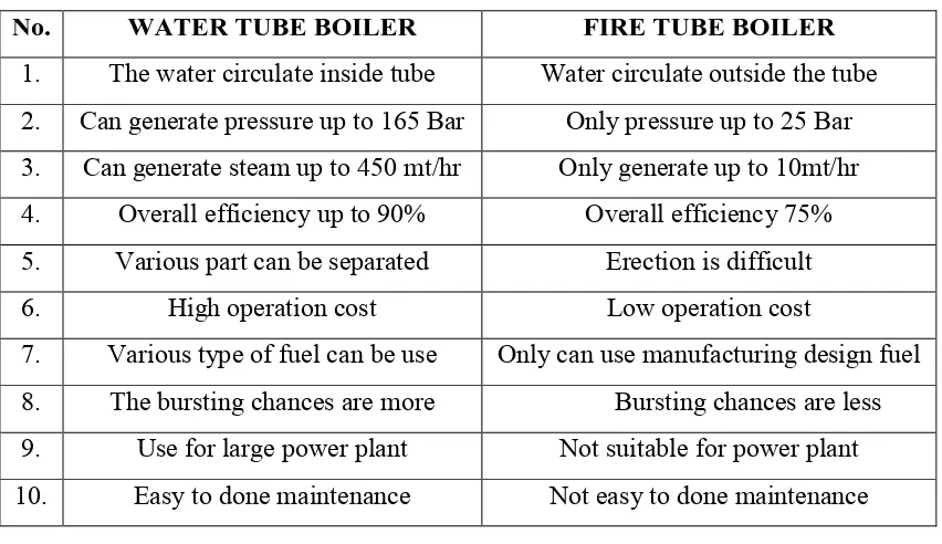
Table 2.1 : Water tube boiler versus fire tube boiler
No. WATER TUBE BOILER FIRE TUBE BOILER 1. The water circulate inside tube Water circulate outside the tube 2. Can generate pressure up to 165 Bar Only pressure up to 25 Bar 3. Can generate steam up to 450 mt/hr Only generate up to 10mt/hr 4. Overall efficiency up to 90% Overall efficiency 75% 5. Various part can be separated Erection is difficult
6. High operation cost Low operation cost
7. Various type of fuel can be use Only can use manufacturing design fuel 8. The bursting chances are more Bursting chances are less 9. Use for large power plant Not suitable for power plant 10. Easy to done maintenance Not easy to done maintenance
2.2 BOILER SUPERHEATER TUBE
8
Figure 2.3 : Super-heater tubes in boiler (Chong, Ahmad, & Purbolaksono, 2002)
2.2.1 Electric Resistance Weld Tube
9
2.2.2 Seamless Tube
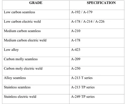
Advocates of seamless tubing prefer no weld seam in the tube wall. This is true as a further protection in the heavier nominal of seamless due to the method of manufacture. Further, the piercing process in making seamless tube impart a tough mill scale to tube surface which appears to make it more resistance to corrosion. Specification in general use for boiler tube is showing in Table 2.2.
Table 2.2 : Specification in general use for boiler tube (ASTM International, 2014)
GRADE SPECIFICATION
Low carbon seamless A-192 / A-179
Low carbon electric weld A-178 / A-214 / A-226
Medium carbon seamless A-210
Medium carbon electric weld A-178
Low alloy A-423
Carbon molly seamless A-209
Carbon moly electric weld A-250
Alloy seamless A-213 T series
Stainless seamless A-213 TP series
10
2.2.3 Alloys in Super-Heater Tube Material
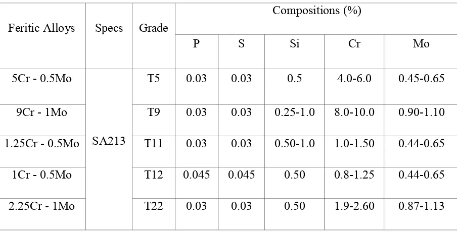
Steels and cast iron are basically alloys of iron and various other elements in the periodic table. The vast majority of steel and all cast iron contain carbon as principal alloying elements. For example, manufacturing standard suggested boiler tube use material from carbon steel intermediate alloys with grade SA213-T22. This grade have 2-1/4 chromium, 1 molybdenum alloy with exceptionally high creep properties but is limited for application to 1125 °F because of possible higher temperature scale exfoliation. It is listed in the ASME boiler code for temperature to 1200 °F. The materials grade are listed by the author is based on the American society of Mechanical Engineers (ASME) standards. Some of the alloy grade that is commonly used as super-heater and re-heater tube listed in Table 2.3. For the first column, it shows the nominal compositions of Ferritic Alloys. The standard specification for Seamless Ferritic and Austenitic Alloy-Steel Boiler, Super-heater, and Heat-Exchanger Tubes are called SA213. The compositions represent the element in the Ferritic Alloys for example P (phosphorus), S (sulphur), Si (silicon), Cr (chromium) and Mo (molybdenum).
Table 2.3 : Feritic alloys used in boiler tube (ASTM international, 2014)
Feritic Alloys Specs Grade
11
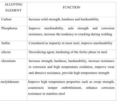
From Table 2.3, it shows that different material grades consist of different of percentages of compositions of alloying. These alloying elements are desirable as it help to improve the mechanical properties of the tube. Table 2.4 shows that the function of each alloying elements. This information will determine what alloying elements have to be adding to meet the specific requirement for the daily uses.
Table 2.4 : Functions of alloying element (Chase Alloys Ltd, 2011) ALLOYING
ELEMENT FUNCTION
Carbon Increase solid-strength, hardness and hardenability
Phosphorus Improve machinability, aids strength and corrosion resistance, increase the tendency to cracking during welding Sulfur Considered as impurity in most steel, improve machinability silicon Deoxidizing agent, hardening of the feritic phase in steel chromium Increase strength, hardness, hardenability, increase resistance
to corrosion and high temperature oxidation, improve wear and abrasive resistance, provide high temperature strength molybdenum Improve high temperature properties such as creep strength,
counteracts temper embrittlement, enhance corrosion resistance in stainless steel
2.3 DEFINITION OF FAILURE ANALYSIS
12
is to understand the root cause of the failure so as to prevent similar failure in the future. In modern business analysis, it is very important due to involve with economic issues.
To verify the failure mode, it is important to determine the factor that explain the how and why the failure occurred such as identifying the root cause event of the failures in super-heated boiler system. The root cause event allows us to explain why the component failed. Many steps need to be followed to determine and carry out an investigation.
Step below is the procedure on how to process will begin:
1. Collect as much the information with possible concerning including part servicing history, part literature, part specification, engineering drawing and etc.
2. Performing non-destructive testing: Check for any crack and internal flaws Check for any crack and external flaw Check metal thickness
Residual stress measurement 3. Select original sample of failed 4. Mechanical testing
5. Microscopic examination and analysis 6. Determine failure mode
7. Chemical analysis
8. Fracture mechanics consideration 9. Analysis of the evidence