Abstract— This paper presents experimental evaluations on braking responses of Magnetorheological Brake (MR Brake) at various current and load. The MR brake consists of a rotating disk that immersed with Magnetorheological Fluid (MR Fluid) where the fluid behavior is changing under influence of magnetic fields. The experiments are performed using MR brake test rig to obtain three output responses namely the angular velocity response, torque response and load displacement response. The MR brake generates maximum torque at high current and causes fast decrement of shaft angular velocity. The effectiveness MR brake torque happens at minimum load with low stopping time.
Keywords— Magnetorheological Brake, Magnetorheological Fluid, Velocity responses, Torque responses, Displacement responses, Stopping Time, Test rig, Load
I. INTRODUCTION
AGNETORHEOLOGICAL fluid is smart fluids which rheological properties is change in the presence of a magnetic field. The rheological properties of the fluid such as elasticity, plasticity or viscosity can be changed by varying the magnetic field. MR fluid consists of a carrier fluid which is synthetic oil or silicone based oil, and ferromagnetic particle (1-10 �m in diameter) [1]. The particles align like a chain structure when exposed with a magnetic field. Thus, the apparent yield stress of the MR fluid will change within milliseconds. The yield stress of MR fluid can be controllable by varying the applied current [2].
MR brake contains 3 mains component which is a rotating rotor/disk, static housing and coil wire. There are a gap between a static body and disk/rotor which are filled with MR fluid. Coil wire is wounded around the MR brake to produce magnetic field when current is applied. The yield strength of the fluid can be controlled by varying the strength of the applied current to the coil. Next, the generating MR braking torque because of shear friction between rotating disk and solidifies of MR fluid within MR brake. Furthermore, the generating MR braking torque depends on material used, an
Ahmad Zaifazlin Zainordin is a master student Faculty of Mechanical Engineering, UTeM. (e-mail: [email protected]).
Dr. Mohd Azman Abdullah, currently he is senior lecturer and member of Autotronic Laboratory in Faculty of Mechanical Engineering, UTeM. (email:[email protected])
PM. Dr. Khisbullah Hudha, is senior lecturer in Faculty of Mechanical Engineering, UPNM. (email:[email protected])
effective working surface are, MR fluid selection, an applied current density and viscous torque of the fluid.[3].
The design and experimental evaluation of a Magnetorheological brake had been researched by Li and Du [4] that introduced an amplifying factor to evaluate brake performance. Park et al. [5] are presented a design optimization procedure using simulated annealing combined with finite element simulations involving magnetostatic, fluid flow and heat transfer analysis. Next, MR fluid selection for MR brake application, such as magnetic circuit design and torque requirements for automotive application was also studied. Karakoc et al.[3] focussed on the investigation of practical MR brake design criteria such as material selection, sealing, working surface area, viscous torque generation and MR fluid selection for basic automotive braking system. Furthermore, Tan et al.[6] are studies braking response of inertia/load by using an electro-rheological (ER) brake for ER-robotic application in term of ER braking velocity response in order to halt the robot arm rapidly. In 2009, Nam and Ahn [7] is proposed the new structure of MR brake with the waveform boundary of rotary disk that generated more resistance torque compare to the conventional MR brake. Furthermore, the MR brake system had been implemented to other application such as joystick and prosthetic knee [8][9][10][11].
This paper presents the MR brake output responses in terms of shaft angular velocity response, torque response and displacement response at various loads and current. The MR brake was subjected with a load that is namely 50N, 100 N and 150 N. The applied current is varies from 1 A until 4 A with increment step of 1 A. Performance of the MR brake is shown by experimental results.
II.EXPERIMENTAL APPARATUS
The MR brake consists of three main parts namely; moving rotor (A), static body (B) and a winding coil (C) that is shown in Fig. 1. The MR brake components are made from mild steel while the winding coil wire is a bronze wire that is commonly used as DC motor coil. The two deep groove ball bearings are fitted at the rotor shaft at each side and been placed at the centre of brake enclosure. The inner diameter for the coil holder is 83 mm, and for the disk/rotor diameter is 80 mm in contact with the MR fluid. The annular gap between static body and rotor or disk is 2.5 mm. The electromagnetic coil has a diameter of 0.35 mm and 250 turnings. The maximum voltage that is supply to the magnetic coil is 20 V with resistance of coil about 5 ohm.
Experimental Evaluations on Braking
Responses of Magnetorheological Brake
Ahmad Zaifazlin. Zainordin, Mohd Azman. Abdullah, and Khisbullah. Hudha
Fig. 1: Cross-section of MR brake
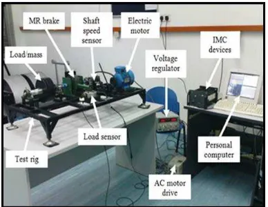
Fig. 2 shows the testing equipment used in the experiment with the load. The load will be attached to the load shaft that is coupled with brake shaft to generate a constant loading or falling load that resultant the net torque produce by MR brake [6]. The function of AC electric motor is to drive the MR brake shaft to desired velocity where it is coupled to the input shaft/rotor of MR brake via pulley an A-type V-belt. The speed from the motor is transmitted to the MR brake shaft using belt tensional that is fitted beside the electric motor. The pulley shaft is connected to the MR brake shaft via jaw coupling and is also the same at load shaft.
Fig. 2: Mechanical assembly of the MR brake test rig
In this equipment, the load cell is employed to measure the braking torque. The MR brake housing is coupled to a load cell via an arm of length of 238 mm. The load cell was calibrated at 1V: 53.4 Nm and the maximum torque can be measured by this sensor is 534 Nm. Furthermore, the load cell is connected with bridge amplifier as the signal conditioning. A DC power supply manufactured by GW-INSTEK is used to supply electric currents to the MR brake electromagnetic coil. The rotational speed of the MR brake shaft was measured by using an ABS speed sensor.The MR brake test rig is equipped with an I/O device for data processing. Next, the Integrated Measurement and Control (IMC) device provides signal processing of the sensory system. The IMC device that is only able to received analogue voltage signal. Then, the signals are digitally processed and stored in a personal computer using FAMOS control software. IMC device is connected to a
personal computer using NetBEUI protocol. All the measured data are displayed in Personal Computer (PC) for the further analysis.
In this work, the speed from the electric motor is passed continuously to the input shaft that coupled with MR brake and load shaft. The rotational speed was set at 1200 [email protected] rad/s for all cases of loads. Then, the current applied to the MR brake starts from 0 A until 4 A with increment step of 1 A. The applied electric current to the magnetic coil will increase the yield stress of MR fluid and slower the shaft angular velocity until stationary. The applied various current to the MR brake coil will overcome the net torque produce by MR brake. In other hand, the saturation of net torque can be obtained by tested various loads and current.
III. MODELING OF MRBRAKE
The characteristics of MR fluid can be described by using a simple Bingham plastic model [12]. The constitutive equation for a Bingham plastic fluid where the total shear
stress (τ) is written as below:
H p
τ τ
=
+
µ γ
• (1) where,τ
H is the yield stress due to the applied magnetic field,,
pH
µ
is the constant plastic viscosity which is considered equal to the non-field viscosity of the fluid, and γ• is the shear strain rate. Based on the Eq. (1), the braking torque generated by the friction of the interface between static and moving parts in the MR fluid inside the MR brake can be written as equations [13]; [3]:2
2
o(
)
i
r
s
b r p
rw
T
N
kH
r dr
h
βπ
µ
=
∫
+
(2)Where r is the radius of the disk,
w
sis the angular velocity of the rotating disk,h
is the thickness of the MR fluid gap between rotor and enclosure, H is the magnetic field intensity corresponding withk
andβ
. The values ofk
andβ
are constant by considering the relationship between the magnetic field intensity and the yield stress of the MR fluid.An integration of Eq. (2) will determine the two types of components of braking torque which are torque generated due to applied magnetic fields
(
T
H)
and torque due to friction and viscosity of the fluids(
T
µ)
. Both torque elements are expressed as follows [3][13].4 4
(
)
2
p o i sT
N
r
r w
h
µ
=
π
µ
−
(3)3 3
2
(
)
3
H o i
T
=
π
Nk
α
r
−
r i
(4) Therefore, the total braking torque produced by MR brake can be written as follow,b H
IV. EXPERIMENTAL RESULTS AND DISCUSSIONS
The MR braking responses was experimentally evaluated at various loads and current. The behaviour of MR braking response in term of shaft angular velocity response, torque response and load displacement response are been compared. By observing the experimental procedure as discussed in previous section II, various input parameter of MR brake is considered. The trend behaviour of the MR brake is influenced by load and current is shown in the results. The MR brake braking behaviour was divided into three sections. First section is described about shaft angular velocity response, second section is about torque response and last section is load displacement response.
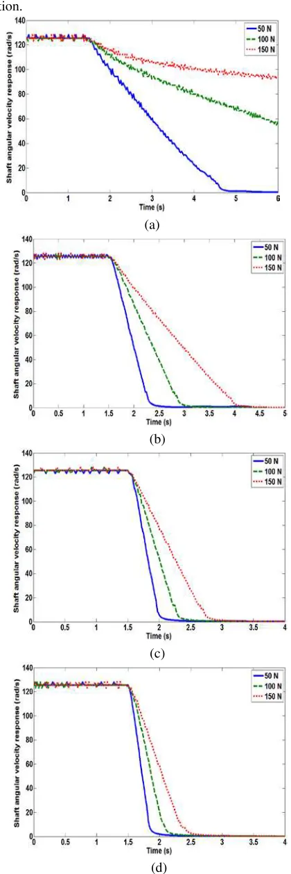
A. Shaft angular velocity response
The main objective of this section is to determine the time response of all inertia to decelerate when current is given. There are three load are tested in the MR braking process that is 50 N, 100 N and 150 N at various current. Fig. 3 shows the shaft angular velocity response versus time at various current. The shaft angular velocity rotates equally for all inertia at desired speed. At 1 A, 50 N of load decelerates slower and shows the trend of inertia is falling down until stationary. When increasing the load to 100 N and 150 N, the shaft angular velocity takes time over than 6 s to become static because of the fluids behavior turned to saturate condition based on applied magnetic. When the applied current is increased from 2 A until 4 A, the response time of the shaft angular velocity is decreased until stationary below 5 s. However, the effectiveness of MR brake reduces when the load is increased. This response is shown in Table I where the MR brake is effective at 50 N which is only takes 0.6 s to halt compared 100 N and 150 N takes 0.8 s and 1.06 s to halt the rotation of all inertia.
TABLE I STOPPING TIME
Current (A) Load (kg)
1 2 3 4 5 3.6 s 1.01 s 0.72 s 0.6 s 10 > 6 s 1.52 s 1.05 s 0.8 s
15 > 6 s 2.6 s 1.31 s 1.06 s
B. Torque response
The effective of MR brake torque at the higher applied current. Fig. 4 shows the behavior of MR brake torque at various input applied current. The applied constant current to the MR brake which will overcome the brake torque is also constant. The MR brake can produce more torque by increasing the current supplied. However, the MR brake cannot generated maximum torque at lower current and it shows the decreasing trend of torque response to halt all the inertia at 1 A for 50 N of load. Also, the time delay of MR fluid to be fully solidifies is 0.3 s using experimental method
which is shown in Fig. 4. The time delay is increases which +0.05 s when load increases with respect of lower load condition.
(a)
(b)
(c)
(d)
(a)
(b)
(c)
(d)
Fig. 4 Torque response versus time at various current; (a) 1 A, b) 2 A, c) 3 A and d) 4 A
The longer steady-state of brake torque response are happen using heavy load. However, the braking torque responses reduce when the load increases. Meanwhile, the torque is remains constant when the load increases from 100 N to 150 N where the maximum torque can be obtained at various current. From the Fig. 4, the average of MR brake torque at various current is obtained. The MR brake net torque at 1 A, 2 A, 3 A and 4 A is 2.54 Nm, 4.46 Nm, 6.31 Nm and 8.1 Nm. The maximum torque can be produced is 8.1 Nm at 4 A because of the MR fluid becomes saturated.
C. Load displacement response
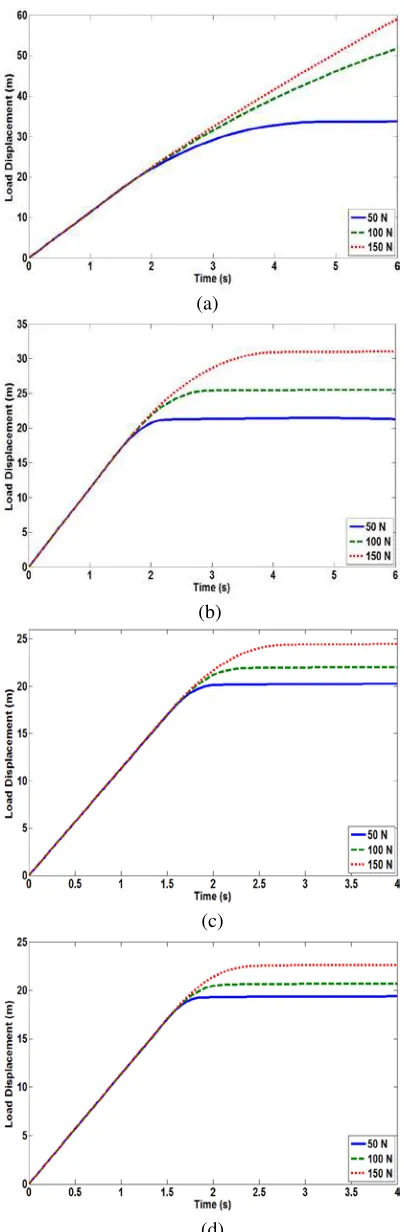
The load displacement responses are obtained by integrating the shaft velocity response. The shaft rotational speed is converted to revolution per second which is divided by 60 s and multiplies with circumference of the load. The load circumference is 565.56 cm. Fig. 5 shows the load displacement response at various load and current. The applied current to the MR brake will decelerates the velocity of the load that coupled rigidly to the MR brake shaft. This will overcome the load displacement response which is reduced significantly based on applied current. At lower current, the load displacement response takes longer time to reach the constant steady-state displacement that can be seen in Fig. 5(a) and 5(b). The fast response of the load to reach the steady-state displacement at the higher current that can be seen in Fig. 5(c) and 5(d). The different distance of load displacement response was captured and shown in Table II. The smaller steady-state displacement at 4 A current which is at 50 N only takes 2.3 m meanwhile 100 N is 4.2 m and 150 N is 5.6 m.
TABLE II
LOAD DISPLACEMENT RESPONSE
Current (A)
Load (N)
1 2 3 4
50 16.6 m 4.3 m 3.2 m 2.3 m
100 > 50 m 8.4 m 4.9 m 4.2 m
150 > 60 m 13.9 m 7.3 m 5.6 m
V.CONCLUSION
(a)
(b)
(c)
(d)
Fig.5 Load displacement response versus time at various current; (a) 1 A, b) 2 A, c) 3 A and d) 4 A
ACKNOWLEDGMENT
The authors gratefully acknowledged the financial support from Universiti Teknikal Malaysia Melaka and The Ministry of Higher Education, Malaysia (MoHE) under Exploratory Research Grant Scheme (ERGS), grant no.: ERGS/1/2012/TK08/UTEM/02/1/E00007
REFERENCES
[1] A. Grunwald and A.G. Olabi, "Sensors and Actuators A : Physical Design of magneto-rheological ( MR ) valve," Sensors And Actuators, vol. 148, 2008, pp. 211-223.
[2] J.D. Carlson and M.R. Jolly, "MRfluid , foam and elastomer devices," Mechatronics, vol. 10, 2000, pp. 555-569.
[3] K. Karakoc, E.J. Park, and A. Suleman, "Design considerations for an automotive magnetorheological brake," Mechatronics, vol. 18, 2008, pp. 434-447.
[4] W.H. Li and H. Du, "Design and experimental evaluation of a magnetorheological brake," Advanced manufacturing technology, vol. 21, 2003, pp. 508-515.
[5] E.J. Park, L. Falcao, and A. Suleman, "Multidisciplinary design optimization of an automotive magnetorheological brake design,"
Computers and Structures, vol. 86, 2008, pp. 207-216.
[6] K.P. Tan, R. Stanway, and W.A. Bullough, "Braking responses of inertia / load by using an electro-rheological ( ER ) brake,"
Mechatronics, vol. 17, 2007, pp. 277-289.
[7] T.H. Nam and K.K. Ahn, "A new structure of a magnetorheological brake with the waveform boundary of a rotary disk," Smart Materials and Structures, IOP, vol. 18, 2009, pp. 1-4.
[8] P. Bachman and A. Milecki, "MR haptic joystick in control of virtual servo drive," Electrorheological (ER) Fluids and Magneto-rheological (MR) Suspensions, Poland: IOP, 2009.
[9] W.H. Li, B. Liu, P.B. Kosasih, and X.Z. Zhang, "A 2-DOF MR actuator joystick for virtual reality applications," Sensors And Actuators, vol. 137, 2007, pp. 308-320.
[10] K.H. Gudmundsson, F. Jonsdottir, and F. Thorsteinsson, "A geometrical optimization of a magneto-rheological rotary brake in a prosthetic knee," Smart Materials and Structures, IOP, vol. 19, 2010, p. 11pp.
[11] J. Chen and W. Liao, "Design and Control of a Magnetorheological Actuator for Leg Exoskeleton*," Robotics and Biomimetics, Sanya, China: IEEE, 2007.
[12] P. Rw, "Engineering applications of fluids with a variable yield stress. PhD thesis. University of California:," Berkeley, CA, 1969. [13] E.J. Park, D. Stoikov, L. Falcao, and A. Suleman, "A performance