ASCEND CLIMBING POLE ROBOT
UMUL FARAH BT AZMI
This report is submitted in partial fulfillment of the award of Bachelor of Electronic Engineering (Telecommunication Electronics) With Honours
Faculty of Electronic and Computer Engineering Universiti Teknikal Malaysia Melaka
iii
“I hereby declare that this report is result of my own effort except for quotes as cited inthe references.”
iv
“I hereby declare that I have read this report and in my opinion this report is sufficient in terms of the scope and quality for the award of Bachelor of Electronic
Engineering
(Telecommunication Electronics) With Honours”
Signature : ……….
Supervisor’s Name : MR. RIDZA AZRI BIN RAMLEE
v
.
This thesis is dedicated to my father and mother for their sacrifice towards my success; it is also dedicated to my supervisor, Mr
Ridza Azri, who taught me that even the largest task can be accomplished if it is done one step at a time.
It may not be enough to contain the words of thanksgiving, it may not capture the endearing love that we have for all of you but now we are making this compilation to let the world know that your
vi
ACKNOWLEDGEMENT
First and foremost, 1 would like to thank to Allah S.W.T for helping and blessing me through all the obstacles that I faced during the work of this project.
In the first place I would like to record my gratitude to Mr. Ridza Bin Azri for his supervision, advice, and guidance from the very early stage of this research as well as giving me extraordinary experiences throughout the work. Above all and the most needed, he provided me unflinching encouragement and support in various ways. I am indebted to him more than he knows.
I gratefully acknowledge to my friends Mohd Rafizi Bin Rahman and Mohd Khairy Bin Ramli for his advice, supervision, and crucial contribution, which made they a backbone of this project to become successfully. Thank you both of you for lending hands during progress of the project. Your contributions are highly appreciated.
vii
ABSTRACT
viii
ABSTRAK
ix
CONTENTS
CHAPTER DESCRIPTION PAGE
PROJECT TITLE i
VERIFYING FORM ii DECLARATION iii
SUPERVISOR APPROVAL iv DEDICATION v ACKNOWLEDGEMENT vi
ABSTRACT vii
ABSTRAK viii
CONTENTS ix
LIST OF TABLES xiii
LIST OF FIGURES xiv
x
I INTRODUCTION
1.0 Introduction 1
1.1 Objectives 3
1.2 Problem statement 3
1.3 Scope of work 3
II LITERATURE REVIEW
2.0 Introduction 5
2.1 Related work 6
2.2 Visual Basic 7
2.3 Serial Port RS 232 9
2.3.1 PC serial port pin out explanations 10
2.3.2 RS232 data flow diagram 11
2.3.3 RS-232 specifications 12
2.4 Peripheral Interface Controller (PIC) 13
2.5 RF Transmitter Module 14
2.5.1 Product Specification 15
2.6 RF Receiver Module 16
2.6.1 Product Specification 16
2.7 MAX 232 17
2.7.1 Voltage level 18
2.7.2 Product Specification 19
2.8 Motor Driver L298 19
2.8.1 Product Features and Specifications 21 2.8.2 Motor Driver L298 operation 21
2.9 DC Motor 22
xi
2.10.1 Calculating Torque in a Geared System 26
2.11 Spring 27
2.11.1 Spring Geometry 28
2.12 Climbing Fundamentals 29
2.13 Fundamental of Taking Surface 30
2.13.1 Suction 31
2.13.2 Magnetic Forces 31
2.13.3 Gripping By Limbs 32
2.13.4 Van Der Waals Force 32
2.14 Robot Mechanism 33
2.15 Architecture 35
2.15.1 Interfacing 36
2.15.2 Robot Assembling 37
III PROJECT METHODOLOGY
3.0 Introduction 38
3.1 Planning Flow Chart and project planning 38 using Gant Chart
3.1.1 Gant Chart 39
3.1.2 Flow Chart 40
3.2 Identify Project Title 41
3.3 Collecting Project Information 41
3.4 Information Searching 41
3.4.1 Books 42
3.4.2 Journals and Articles 42
3.4.3 Internet and Web Pages 42
3.4.4 Discussion with lecturer 42 3.5 Create, Understand Project Circuit 43
and Programming
3.6 Selecting Projects Component 43
3.7 Circuit Testing 43
xii
3.9 Block Diagram 44
IV RESULT AND ANALYSIS
4.0 Introduction 45
4.1 Process 45
4.2 Circuit Schematic 50
4.2.1 Transmitter circuit 50
4.2.2 Receiver Circuit 52
4.2.3 Motor Driver L298 54
4.3 Construction process 56
4.4 PIC 16F877A Source Code 59
4.5 Visual Basic Source Code 66
4.6 Analysis and Discussion 72
V CONCLUSION AND SUGGESTIONS
5.0 Introduction 73
5.1 Conclusion 73
5.2 Suggestions 74
xiii
LIST OF TABLES
NO DESCRIPTION PAGES
Table 2.1 The RS 232 specification 12
Table 2.2 Type TX 315/433 MHz 14
Table 2.3 RF_TX_315 and RF_TX_433 Specifications 15 Table 2.4 RF Receiver Modules 315MHz or 433MHz 16 Table 2.5 RF_RX_315 and RF_RX_433 specifications 17 Table 2.6 Voltage levels 18 Table 4.1 The measurement of climbing speed in forward movement 46 Table 4.2 Differences before and after modification 72
xiv
LIST OF FIGURES
NO DESCRIPTION PAGES
Figure 1.1 The Visual Basic interfacing and connection 4 to the PIC
Figure 2.1 Visual Basic 7
Figure 2.2 Interfacing using Visual Basic 8
Figure 2.3 Serial port RS 232 9
Figure 2.4 Serial port RS 232 pin diagram 9
Figure 2.5 Data flow diagram 11
Figure 2.6 PIC16F877A pin- diagram and basic connection 13
Figure 2.7 Max 232 pin diagram 17
Figure 2.8 Max232 Connection 18
Figure 2.9 Microcontroller control of motor driver 20 Figure 2.10 Logic table of operation 22
Figure 2.11 10 rpm DC gear motor 23
Figure 2.12 The wheel rotation 24
Figure 2.13 The dimension of torque 25
Figure 2.14 Motor torques in geared system 26 Figure 2.15 Spring Geometry of Extension springs 28
xv
Figure 2.17 A schematic view of climbing mechanism 34 Figure 2.18 Side View and Top View of Ascend Climbing Pole Robot 34
Figure 2.19 Wheels 35
Figure 2.20 Ascend Climbing Pole Robot architecture 35 Figure 2.21 The Visual Basic control panel 37
Figure 3.1 Gant Chart 39
Figure 3.2 Flow chart of implementation planning 40 Figure 3.3 The block diagram of Ascend Climbing Pole Robot 44 Figure 4.1 Graph shown the movement of robot in time and distance 47
for Forward movement
Figure 4.2 Graph shown the climbing speed in time and distances 47 separates by the value of ranges
Figure 4.3 Figure shown the movement of robot in time and distance 48 every 2seconds from 0seconds until 22 seconds
Figure 4.4 The Visual Basic control panel 49
Figure 4.5 Transmitter circuit schematic 50
Figure 4.6 Transmitter PCB track design 51
Figure 4.7 Transmitters Schematic Printed 51
Figure 4.8 Receiver Circuit Schematic 52
Figure 4.9 Receiver PCB track design 53
xvi
LIST OF APPENDICES
NO DESCRIPTION PAGES
Appendix A Technical Paper Development of Automatic 77 Self Balancing Control System For a Tree Climbing Robot
Appendix B DC Motor 81
CHAPTER 1
INTRODUCTION
1.0 Introduction
An increasing interest in the development of special climbing robots has been witnessed in last decade. Motivations are typically to increase the operation efficiency in dangerous environments or difficult-to-access places, and to protect human health and safety in hazardous tasks. Climbing robots with the ability to maneuver on vertical surfaces are currently being strongly requested by various industries and military authorities in order to perform dangerous operations such as inspection of high-rise buildings spray painting and sand blasting of gas tanks, maintenance of nuclear facilities, aircraft inspection, surveillance and reconnaissance, assistance in fire fighting and rescue operations. Such capabilities of climbing robots would not only allow them to replace human workers in those dangerous duties but also eliminate costly scaffolding.
2
In the literature is a surface climber and must adhere to the surface. Climbing pole robot was built to climb up and down a pole. The parameters that effect the operation and stability of this robot for the climbing up and sliding down motion include the weight of various components, dimensions of linkages, angles of inclination, spring constants, clearances and coefficients of friction between the pole and gripping arms, also climbing speed.[3]
Moreover, some new and important tasks for climbing robots can be introduced. Cleaning electric lights on lampposts in highways is one of these new tasks. Air pollution in metropolitan areas is the main cause of dirt on highway light bulbs. Therefore, the highway lighting systems should be cleaned on regular bases in order to have the required light in the highways without resorting to more powerful and energy consuming lighting systems. Manual cleaning of highway lighting systems is a very dangerous and traffic disturbing task [1, 2]
3
1.1 Objective
The main objective of this project is to introducing the Ascends Climbing Pole Robot assembling by using Visual Basic Interfacing. Referred to previous researcher most likely used the remote as the controller to control their robot. But in this project, visual basic has been used to control as interfacing. Another objective is to design and develop pole climbing pole robot that has ability to climb on the pole vertically. The ability this robot to climb up and down vertically could simplify human task which need they to reach something at the high pole. Next objective is to ensure that the robot can climb smoothly and stable over the pole.
1.2 Problem Statement
The electrical problems in high places will endanger lives because they do not know what is happening in these places because not be monitored as they may occurs a short circuit and other electrical problems. In addition, air pollution in metropolitan areas is the main cause of dirt on highway light bulbs. Therefore, the highway lighting systems should be cleaned on regular bases in order to have the required light in the highways without resorting to more powerful and energy efficient lighting consumes. Manual cleaning of highway lighting systems is a very dangerous and interferes with traffic duties. In related robots and the natural and artificial climbing mechanisms are reviewed and the design of the Ascends Climbing Pole Robot is described.
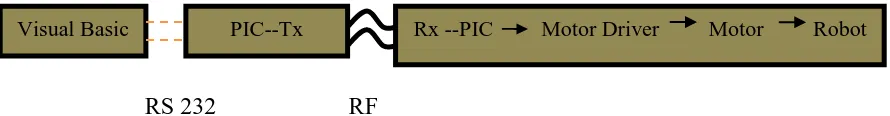
1.3 Scope of work
4
ensure it was function. Another scope of work is by develop Visual Basic Interfacing that including the source code needs to be run and drive up the robot from personal computer (Pc). This interfacing is connected to the PIC circuit through the serial port RS 232.
RS 232 RF
Figure 1.1: The Visual Basic interfacing and connection to the PIC
CHAPTER 2
LITERATURE REVIEW
2.0 Introduction
In this chapter will explain in detail about the research literature. Some concept of a project is described. This is because an understanding of the work will assist in preparing project end of this year.
6
2.1 Related Work
The climbing mechanism is generally based on suction cups and magnetic ends, which require smooth or metallic ferrous surfaces respectively. Other robot have been designed for special situations, for example type of pole climbing robot is using grippers as the robot hands and legs where the robots use the grippers to climb the pole objects. Most of the robot is created by using pneumatic system to control the grippers and the movement of the robot. This because the pneumatic system can grip tighter on the pole objects compare by using DC motor or servo motor as the gripper. But this type of robot needs an air compressor to make it functioning. The movement of the robot also limit by the length of air cables. If the robot needs to climb tall pole objects, the robot need long air cables. The movement also limit by the weight of the robot because the component for pneumatic system is heavy compare to the robot that using aluminums and electronic components [4].
Other types of robot are snake climbing robot. This climbing robot is designed like a snake and used the nanotechnology as its skin. Then, the movement of this robot is quite similarly like the movement of a snake while climbing a tree. However, the cost to create this cylinder climbing robot is very expensive since it is not commercially in use yet [4].
7
In addition, the wheels on these limbs should not add any constraints to the motion of the robot. Moreover it can be assumed that the forces exerted by the springs produce large enough normal components to bring the lower wheels in good contact with the surface of the pole so that the wheels do not slip [5].
2.2 Visual Basic
Visual Basic (VB) is the third-generation event-driven programming language and integrated development environment (IDE) from Microsoft for its COM programming model. Visual Basic was derived from BASIC and enables the rapid application development (RAD) of graphical user interface (GUI) applications, access to databases using Data Access Objects, Remote Data Objects, ActiveX Data Objects, and creation of ActiveX controls and objects. [13].
Forms are created using drag and drop techniques. A tool is used to place controls for examples, text boxes, and buttons, on the form (window). Controls have attributes and event handlers associated with them. Default values are provided when the control is created, but may be changed by the programmer. Many attribute values can be modified during run time based on user actions or changes in the environment, providing a dynamic application. For example, code can be inserted into the form resize event handler to reposition a control so that it remains centered on the form, expands to fill up the form, etc. By inserting code into the event handler for a key press in a text box, the program can automatically translate the case of the text being entered, or even prevent certain characters from being inserted [13].
8
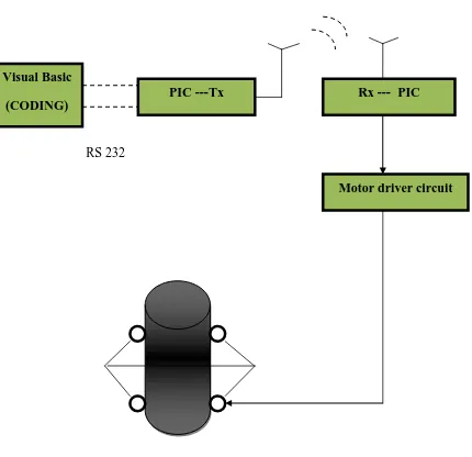
Interfacing using Visual Basic
RS 232
Figure 2.2: Interfacing using Visual Basic Visual Basic
(CODING)