A Low Cost 4 DOF Remotely Operated Underwater Vehicle Integrated
With IMU and Pressure Sensor
M. S. M. Aras
1, F.A.Azis
2, M.N.Othman
3, S.S.Abdullah
41
Department of Mechatronics, Faculty of Electrical Engineering, Universiti Teknikal Malaysia Melaka, Hang Tuah Jaya, 76100 Durian Tunggal, Melaka Malaysia.
Tel: + 606-5552284, Fax: + 606-5552222, E-mail: [email protected]
2
Department of Mechatronics, Faculty of Electrical Engineering, Universiti Teknikal Malaysia Melaka, Hang Tuah Jaya, 76100 Durian Tunggal, Melaka Malaysia.
Tel: + 606-5552319, Fax: + 606-5552222, E-mail: [email protected]
3
Department of Mechanical Engineering, Faculty of Technology Engineering, Universiti Teknikal Malaysia Melaka, Hang Tuah Jaya, 75450 Ayer Keroh, Melaka Malaysia.
Tel: + 606-2346563, Fax: + 606-2346526, E-mail: [email protected]
4
Department of Electric and Electronics, Malaysia -Japan International Institute of Technology, Universiti Teknologi Malaysia, International Campus Jalan Semarak, 54100 Kuala Lumpur,
Malaysia.
Tel: + 603-26154707, Fax: + 603-26910342, E-mail: [email protected]
Abstract
This paper presents the development of low cost Remotely Operated Underwater Vehicle (ROV) for underwater activities. In underwater industries, the constraint issues to the divers are the dangerous environment and depth pressurized that affect human bodies. Otherwise high cost is needed for each underwater task. Many industries are involved on robot development in order to reduce human works as well a s increase productivity, efficiency and monitoring. Therefore, ROV is designed in order to replace the divers itself. The micro ROV was design based in three goals maneuverability, performance and future industrial implementation (ability to carry payload) with minimum cost. The Peripheral Interface Controller (PIC) is used to control the movement of this ROV. Standard test method for pressure testing, buoyancy and controlling efficiencies are considered on testing the ROV. In this project the focus will be in controlling an ROV in a multi-axis motion in order to maintain its desired position. The verified algorithms will then be tested on the actual prototype micro ROV. This project will give much benefit for related underwater industries by looking at ROV's features with needed minimum cost of implementation.
Keywords:
Remotely Operated Underwater Vehicle, Pressure Sensor, IMU sensor; NI DAQ Card
Introduction
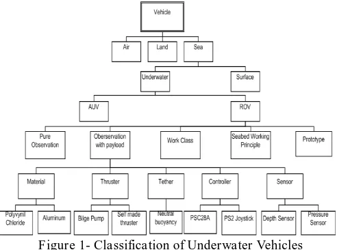
Underwater vehicles can be classified into two basic categories such as Manned Underwater Vehicles and Unmanned Underwater Vehicles (UUVs) [1-5]. Unmanned Underwater Vehicles (UUVs) is the term referring to
Remotely Operated Underwater Vehicles (ROV) and Autonomous Underwater Vehicles (AUVs). This can be shown in Figure 1. These two types of UUVs contribute to the same control problems [4]. These vehicles have subsisted for over 100 years and have known as an interesting area from researchers and industries [4], [5]. Unmanned underwater vehicles (UUVs) have provided an important tool in pilot free underwater operations due to the increased operating range and depth. Additionally operation survival and less risk to human life are also important factors. Typical applications of UUVs today incorporate; survey, search and reconnaissance, surveillance, inspection, recovery, repair and maintenance, and construction. Particularly in the offshore industry, UUVs have become indispensable [1]. or in the air. ROVs are unoccupied, highly maneuverable and operated by a person aboard a vessel [7][8]. They are linked to the ship by a tether sometimes referred to an umbilical cable, a group of cables that carry electrical power, video and data signals back and forth between the operator and the vehicle.
dynamics of underwater vehicles followed by intelligent controller design [13]. The implementation phase will be verified through MATLAB SIMULINK platform. The verified algorithms will then be tested on the actual prototype mini ROV.
Figure 1- Classification of Underwater Vehicles
This paper is organized as follows. Section 1 describes brief introduction of ROV system. Section 2 presents the design methodology. Section 3 describes simulation results using the Solidworks software and hardware implementation with field testing results. Finally, Section 4 shows the final remarks.
Design Methodology
The project can be divided into two major parts, Hardware and Electronics development and Software development:
Hardware and Electronics Development
Hardware major phases include:
Preliminary study of ROV structure, sensors and communication device
Design and develop active sensors system and communication device between ROV and control panel
Integrated the ROV with the designed sensor for further test and trouble shoot the ROV hardware and integrated sensor system.
Interface the ROV hardware development with the firmware arrangement to complete the task.
The first phase for developing the hardware is by having preliminary study and design the ROV structure, sensors and related communication device. Figure 2 shows the overall hardware system diagram. This phase is focus on how to choose the suitable sensors and also to know details about ROV construction and structure. The types of communication device also review on this phase.
Figure 2- The overall hardware system diagram
Software Development
The software part can be divided into five major phases:
Preliminary study of Conventional and Intelligent Controller (IC) such as PID and Fuzzy Logic Controller (FLC) respectively, and trajectory coordinate derivation for Remotely Operated Underwater Vehicle (ROV)
Design and development of IC for real time simulation, data input, coordinate processing and storing image method which captured by ROV using Windows Software programming (Visual Basic Platform/MATLAB )
Design a Graphical User interface (GUI) for simulation, data input, data storage, processing and other ROV key instruction control.
Hardware and software communication setting and testing
Finalize and upgrading program
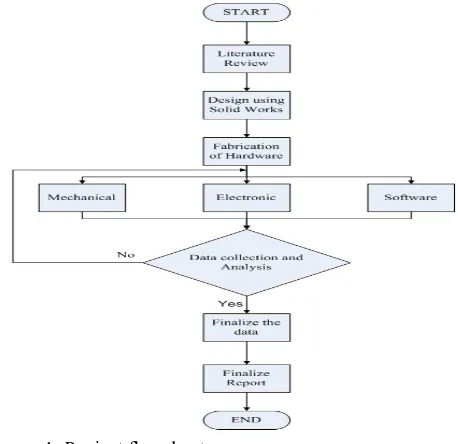
Figure 3 shows the multi-sensor ROV system structure for the firmware and software part. The first phase will be the preliminary study of the controller part and the compiler related to design the system control panel. Figure 4 shows a simple flowchart of project methodology that will be followed.
Figure 4- Project flowchart
Implementation and Results
CAD Design
In the beginning, the prototype of ROV will be designed using Solidworks software as shown in Figure 5. Four thrusters are used and produced four degree of freedom movement. Other than that, some testing and simulation can be tested in Solidwork software before implement or fabricate in real time. Some parameters such as center of gravity of the structure can be easily extracted from this ROV’s drawing [15].
Figure 5-: Solidwork drawing for ROV
In Solidworks software, some plots and animations can be carried out such as cut plot, surface plot, and animation of flow trajectory [18]. Cut plot shows the strength of ROV overcomes water flow to maintain stability which means the strength of water flow onto ROV will affect the stability as shown in Figure 6. Also the surface plot can be plotted to show which one of the ROV part will be more pressure applied. The red color is the higher pressure strength applied to ROV as shown in Figure 7. It is almost similar with cut plot and flow trajectory shows animation of flow of water through ROV.
Figure 6- Cut Plot
Figure 7- Surface Plot
Figure 8- Animation of Flow Trajectory
Hardware Implementation
Figure 9 shows the final ROV frame with vision system and ballast tank. Cylinder type of pressure hull is redesign as compare to previous type (rectangular shape) to withstand the pressurized flow. The pressure hull is using PVC pipe with end cap for both side. To increase withstand of pressure to the PVC pipe, another PVC connector will be put. Waterproof silicon is used as the sealing method. From the ROV frame, the measurement of buoyancy force is carried out so that ROV can easily submerge as long as it follows set points. The weight will be used to overcome the buoyancy problem by playing around some buoyancy experiments.
45o angle for turning right and left as shown in Figure 10 and Figure 11.
Figure 9- ROV ready to test
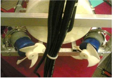
Figure 10- Vertical thruster and control panel
Figure 11- Horizontal Thruster with 45o
The best material to be a ROV frame is solid aluminum but the cutting machine cost by desired ROV shape is expensive. The cost for aluminum rectangular solid plane with size 4 feet x 2 feet is around RM 600. This price is not including laser cutting to do a frame as needed. For aluminum solid frame the total estimate around RM 1500 compared with aluminum hollow plane around RM 250. The total cost for build a simple ROV is estimated below RM 5000.
Specifications of ROV
Table 1 -the specifications of ROV.
Parameter Specifications
Product name UTeRG- SMART ROV 1 Type (eyeball/ observation/
workclass)
Frame – Aluminium Pressure Hull - PVC
Year of initial development 2012
Size of rov (lwh) (mm) 300 mm x 600 mm x 450 mm Weight of rov in air (kg) 18 kg
Size of surface control unit (lwd)
Only control panel (joystick)
Laptop 12’ for Monitor
Weight of surface control unit (kg)
2kg
Input power requirements vehicle
24 V – four Thruster 12 V – Vision+sensor
Speed/ current/ workability performance
2 knots
Forward/ lateral/ vertical up/ vertical down (kts.)
2knot forward,1.5knot lat.,1.5knot up/dwn,
Deployment up/ down [m/min]
variable depending on weighting
Thrust forwards/ backwards [kg]
10 kg forward / 8kg reverse.
Thrust sideways [kg] 10kg Thrust up/ down [kg] 10kg Max depth rating (m) 50m Max payload (kg) 2.5kg Operating temperature (oC) -20o - +85o Number and type of
thrusters
4
Horizontal 2 Vertical 2
Auto depth control y/n Y (Next planning) Auto heading control y/n No
Auto pilot y/n No Number and type of lights (standard/ survey mode)
1 set of LED
Number and type of camera's (standard/ survey mode)
1
Sensor Depth sensor and IMU Main applications survey, inspection
Sensor part
Figure 12 shows the functionality testing of integrated sensor by using National Instrument DAQ card. Integrated sensor is combination between pressure sensor, Inertial Measurement Unit (IMU), and Digital Compass. Pressure sensor is used to determine the current depth of ROV. The IMU is used for platform stability of ROV. The IMU is the complete inertial system that includes a dual-axis gyroscope and tri-axis accelerometer. IMU Board is now available with smaller, better, faster, and cheaper components by Cytron. The IMU board uses a standard 0.1" footprint and includes all outputs from both the IDG500 Gyro and ADXL335 Accelerometer ICs [16]
.
The Digital Compass fully integrated compass module that combines 2-axis magneto-resistive sensors with the required analogue and digital support circuits, and algorithms for heading computation [17]. Figure 13 shows the schematic diagram for integrated sensor.Figure 12- The integrated sensor is using Nl DAQ card
Figure 13- Schematic diagram of integrated sensor
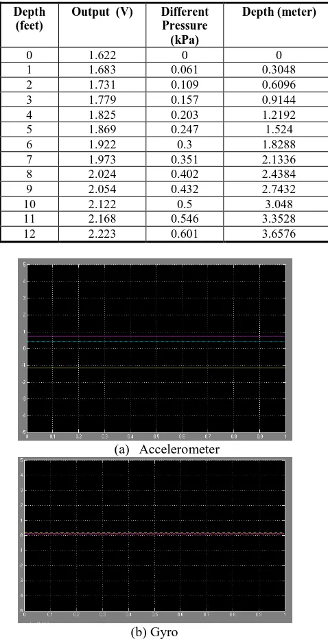
From experiments pressure sensor data stated that every 25kPa give an output of 0.25V. Pressure Sensor can measure up to 700 kPa equivalent to 71.38 meter deep as shown in Figure 14. Experiment held on pool area at Kompleks Renang MBMB with depth up to 12.5 feet. Result of this experiment as shown in Table 1.
Figure 14-Output vs absolute pressure
Table 2-The Result 0f Pressure Sensor
Depth (feet)
Output (V) Different Pressure (kPa)
Depth (meter)
0 1.622 0 0
1 1.683 0.061 0.3048
2 1.731 0.109 0.6096
3 1.779 0.157 0.9144
4 1.825 0.203 1.2192
5 1.869 0.247 1.524
6 1.922 0.3 1.8288
7 1.973 0.351 2.1336
8 2.024 0.402 2.4384
9 2.054 0.432 2.7432
10 2.122 0.5 3.048
11 2.168 0.546 3.3528
12 2.223 0.601 3.6576
(a) Accelerometer
(b) Gyro
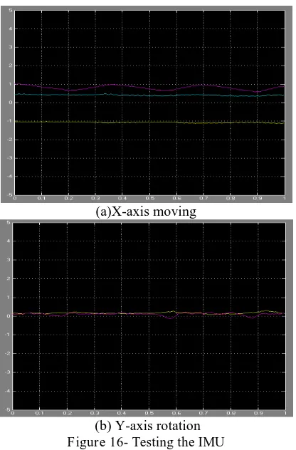
(a)X-axis moving
(b) Y-axis rotation Figure 16- Testing the IMU
Figure 15 (a) and (b) is the separate results for accelerometer and gyro to get best analyze. The offset error can be measure for gyro results as shown in Figure 15 (b) with the offset error from 0.1 to 0.15. For accelerometer, the offset error is not yet being measured. Figure 16 shows the testing of IMU when ROV is moving in X-axis and Y-axis with a low error when moving in Y-axis.
Conclusion
The development of Remotely Operated underwater Vehicle (ROV) and integrated sensor with low cost implementation are successfully done. Integrated sensor gives the best results for performances of ROV. The total cost for build an UTeRG SMART ROV 1 is estimated below RM 5000. The ROV was design based on three goals which are maneuverability, performance and future industrial implementation (ability to carry payload) with minimum cost. This project will give much benefit for related underwater industries by looking at ROV's features with needed of minimum cost implementation. Future planning to upgrade the ROV is to make it to be under actuated condition and design the auto controller for depth control and navigation system.
Acknowledgement
Special appreciation and gratitude to honorable University (Universiti Teknikal Malaysia Melaka, UTeM and UniversitiTeknologi Malaysia, UTM) especially to the both Faculty of Electrical Engineering for providing the financial as well as moral support to complete this project successfully.
References
[1] Robert D. Christ and Robert L. Wernli Sr., The ROV Manual: A User Guide for Observation-Class Remotely Operated Vehicles, Elsevier Ltd., Oxford UK,First edition, 2007. [2] Gian luca Antonelli, Underwater Robots: Motion and Force
Control of Vehicle- Manipulator Systems, Springer, Cassino Italy, Second Edition, 2006.
[3] Roy Kim Lea, Control of a Tethered Underwater Flight Vehicle, Ph.D thesis, University of Southampton, May 1998. [4] Louis Andrew Gonzalez, Design, Modelling and Control of an
Autonomous Underwater Vehicle, B.Eng. thesis, The University of Western Australia, October 2004.
[5] T.I. Fossen, Guidance and control of ocean vehicles, Wiley, New York, 1994.
[6] K.R. Goheen and E.R. Jefferys, “The application of alternative
modelling techniques to ROV dynamics”, in Proceedings of IEEE InternationalConference Robotics and Automation, vol. 2, pp. 1302-1309, May 1990.
[7] P. Maurya, E. Desa, A. Pascoal, E. Barros, G.S. Navelkar, R. Madhan, A.A.M.Q. Mascarenhas, S. Prabhudesai, S. Afzulpurkar, A. Gouveia, S.Naroji, and L. Sebastiao, “Control of the Maya AUV in the vertical and horizontal planes: Theory
and practical results”, in Proceedings MCMC2006 -7th IFAC Conference on Maneuvering and Control of Marine Craft, Lisbon, Portugal, 2007.
[8] A. M. Plotnik and S. M. Rock (2007), "A multi-sensor approach to automatic tracking of midwater targets by an ROV," in Proceedings of the AIAA.
[9] J. V.Morató and S. G. Castro (2007), “Autonomous Underwater Vehicle Control,” in Instrumentation ViewPoint.
[10] Design, Modelling and Control of a n Autonomous Underwater Vehicle Louis Andrew Gonzalez Master Thesis 2007 The University of Western Australia.
[11] J.C. Kinsey, R.M. Eustice, and L.L. Whitcomb (2006),
“Underwater Vehicle Navigation: Recent Advances and New Challenges,” Proc. IFAC Conf. on Manoeuvring and Control of Marine Craft, Lisbon, Portugal, In Press.
[12] Autonomous Underwater Vehicle— “Camera” Stephen Hsu, Chris Mailey, Chris Montgomery, Ryan Moody, duke & NC state university, 2006.
[13] KashifIshaque, S. S. Abdullah, S. M. Ayob and Z. Salam (2010).Single Input Fuzzy Logic Controller for Unmanned Underwater Vehicle, Journal of Intelligent and Robotic Systems. Vol. 59, No. 1, July 2010.
[14] Lam Kong Shen, Faculty of Electrical Engineering UTM. Maneuver System of Remotely Operated Underwater Vehicle (ROUV) .May 2011.
[15] M.S.M. Aras, F.L. Sudirman, F.Ashikin Ali, F.A.Azis. SMSSA. Hamid, A.S.M.Nor, L.W.Teck, Fakulti of Electrical Engineering, UTeM. Underwater Technology Research Group (UTeRG) Glider for monitoring and Surveillances Applications, 2011.
[16] Timothy Phajdak, Jonathan Leahey, Mark Crossman, Ryan Ferguson, Dalhousie University. First Build Report Group 2: Aquatic Cave Exploration Remotely Operated Vehicle (ACE ROV) 18th November 2010.
[17] Damian Matthews, Janelle Draubay, Ty Nowotny, Ben Creed, UC Davis MAE Dept. & College of Engineering. Aggie Deep ROV Technical Report 1st Jun 2008.