UNIVERSITI TEKNIKAL MALAYSIA MELAKA
SMART HOME APPLICATION USING GSM
This report submitted in accordance with requirement of the Universiti Teknikal Malaysia Melaka (UTeM) for the Bachelor Degree of Engineering Technology
(Industrial Electronics) with Honours
by
NORLEHA BINTI ISRONI B071210276
930918105916
UNIVERSITI TEKNIKAL MALAYSIA MELAKA
BORANG PENGESAHAN STATUS LAPORAN PROJEK SARJANA MUDA
TAJUK: Smart Home Application Using GSM
SESI PENGAJIAN: 2015/16 Semester 2
Saya NORLEHA BINTI ISRONI
mengaku membenarkan Laporan PSM ini disimpan di Perpustakaan Universiti Teknikal Malaysia Melaka (UTeM) dengan syarat-syarat kegunaan seperti berikut:
1. Laporan PSM adalah hak milik Universiti Teknikal Malaysia Melaka dan penulis. 2. Perpustakaan Universiti Teknikal Malaysia Melaka dibenarkan membuat salinan
untuk tujuan pengajian sahaja dengan izin penulis.
3. Perpustakaan dibenarkan membuat salinan laporan PSM ini sebagai bahan pertukaran antara institusi pengajian tinggi.
4. **Sila tandakan ( )
SULIT
TERHAD
TIDAK TERHAD
(Mengandungi maklumat yang berdarjah keselamatan atau kepentingan Malaysia sebagaimana yang termaktub dalam AKTA RAHSIA RASMI 1972)
(Mengandungi maklumat TERHAD yang telah ditentukan oleh organisasi/badan di mana penyelidikan dijalankan)
________________________
FAKULTI TEKNOLOGI KEJURUTERAAN
PENGKELASAN LAPORAN PSM SEBAGAI SULIT/TERHAD LAPORAN PROJEK SARJANA MUDA TEKNOLOGI KEJURUTERAAN ELEKTRONIK (ELEKTRONIK INDUSTRI): NRLEHA BINTI ISRONI
Sukacita dimaklumkan bahawa Laporan PSM yang tersebut di atas bertajuk “Smart Home Application using GSM” mohon dikelaskan sebagai *SULIT / TERHAD untuk tempoh LIMA (5) tahun dari tarikh surat ini.
2. Hal ini adalah kerana IANYA MERUPAKAN PROJEK YANG DITAJA OLEH SYARIKAT LUAR DAN HASIL KAJIANNYA ADALAH SULIT.
Sekian dimaklumkan. Terima kasih.
Yang benar,
________________
Tandatangan dan Cop Penyelia
* Potong yang tidak berkenaan
iv
DECLARATION
I hereby, declared this report entitled “SMART HOME APPLICATION USING GSM” is the results of my own research except as cited in references.
Signature :………
Name : Norleha Binti Isroni
v
APPROVAL
This report is submitted to the Faculty of Engineering Technology of UTeM as a partial fulfilment of the requirements for the degree of Bachelor of Electronics Engineering Technology (Industrial Electronics) (Hons.). The member of the supervisory is as follows:
vi
ABSTRACT
vii
ABSTRAK
viii
DEDICATIONS
Alhamdulillah, praise to the Almighty Allah S.W.T
This thesis is dedicated to:
My family,
My Supervisor,
My lecturers,
And all my friends
ix
ACKNOWLEDGMENTS
Alhamdulillah, thank you Allah because of His blessing, I finally complete and finish my final year project successfully.
During the process to complete this project, there are lots of problems I have faced. With the guidance and support, I finally complete the project and report within the time given.
Here, I would like to take this opportunity to thank to my supervisors, Mr Mohd Fauzi Bin Ab Rahman and Puan Raeihah Binti Mohd Zain for their guidance, advice, inspiration and constructive suggestions that are very helpful for me in completing this project. I really appreciate their dedication to ensure the completion of this “Smart Home Application using GSM” project.
x
TABLE OF CONTENTS
DECLARATION ... iv
APPROVAL ... v
ABSTRACT ... vi
ABSTRAK ... vii
DEDICATIONS ... viii
ACKNOWLEDGMENTS ... ix
TABLE OF CONTENTS ... x
LIST OF FIGURES ... xiii
LIST OF TABLE ... xv
LIST OF SYMBOLS AND ABBREVIATIONS ... xvi
CHAPTER 1 ... 1
1.1 Project Background ... 1
1.2 Problem Statement ... 2
1.3 Objective Project ... 3
1.4 Scope of Project ... 4
1.5 Project Methodology ... 4
1.6 Thesis Outlines ... 5
CHAPTER 2 ... 6
2.1 Electrical Control System Uses GSM Technology ... 6
xi
2.4 Global System for Mobile (GSM) Communication ... 8
2.4.1 Advantages of GSM ... 8
2.4.2 Services Provided by GSM ... 9
2.4.3 Architecture of GSM ... 9
2.4.4 AT Command ... 11
2.5 Arduino Board ... 12
2.5.1 Arduino Uno ... 12
2.6 Software Design ... 14
2.6.1 Proteus 7 Proffesional ... 14
2.7 Software Programming ... 16
2.7.1 Arduino Integrated Development Environment (IDE) ... 16
2.8 Relay ... 17
2.9 Electromagnetic Lock ... 18
2.10 Light Sensor Module ... 19
CHAPTER 3 ... 20
3.1 Introduction of Methodology ... 20
3.2 Project Development Flowchart ... 21
3.3 Block Diagram ... 22
3.4 Program Development ... 23
3.5 Arduino IDE Software ... 25
3.6 Circuit Development ... 27
xii
3.6.2 Light Sensor Module ... 28
3.6.3 GSM Serial Communication ... 29
3.6 HyperTerminal ... 30
CHAPTER 4 ... 34
4.1 Software Development ... 34
4.2 Hardware Development and Testing ... 37
4.3 Experimental Results ... 38
4.3.1 Circuit of the System ... 38
4.3.2 Relay Circuit ... 39
4.3.3 Light Sensor Module ... 41
4.4 GSM Network Analysis ... 43
4.5 Light Sensor Analysing ... 47
4.6 Discussion ... 49
CHAPTER 5 ... 51
5.1 Conclusion ... 51
5.2 Future Work ... 52
APPENDIX A ... 54
APPENDIX B ... 59
APPENDIX C ... 61
xiii
Figure 2.1: Block Diagram of Door Lock System) ... 7
Figure 2.2: General Architecture of A GSM Network ... 10
Figure 2.3: Arduino UNO Board (www.arduino.cc) ... 13
Figure 2.4: Layout of Proteus ISIS ... 14
Figure 2.5: Example of PCB Design in Proteus ARES ... 15
Figure 2.6: Windows Layout of the Arduino IDE ... 16
Figure 2.7: Relay for Switching ... 17
Figure 2.8: Electromagnetic Lock ... 18
Figure 2.9: Basic Concept of Electromagnetism ... 18
Figure 2.10: Light Sensor Module ... 19
Figure 3.1: Flowchart of Project Development ... 21
Figure 3.2: Block Diagram of the System ... 23
Figure 3.3: Flowchart of the System ... 24
Figure 3.4: Location of Arduino Application ... 25
Figure 3.5: Window of Arduino IDE Software ... 26
Figure 3.6: Port Selection ... 26
Figure 3.7: Relay Circuit (Top View) ... 27
Figure 3.8: Relay Circuit (Back View) ... 28
Figure 3.9: Connection of the Light Sensor Module... 29
Figure 3.10: Connection between GSM and Arduino Board ... 29
Figure 3.11: HyperTerminal Windows ... 30
Figure 3.12: Device Manager Windows ... 31
Figure 3.13: Com Port Windows ... 31
Figure 3.14: Port Setting Windows ... 32
Figure 3.15: Command Windows ... 33
Figure 3.16: Test Command ... 33
Figure 4.1: Define All Pins are Used on Arduino ... 34
Figure 4.2: Set the Input and Output Pins ... 35
Figure 4.3: Relay Testing Program ... 35
Figure 4.4: Define All Pins are Used on Arduino ... 36
Figure 4.5: Light Sensor in the Bright Place ... 37
Figure 4.6: Light Sensor in the ark Place ... 38
Figure 4.7: Hardware Development ... 39
Figure 4.8: Relay Circuit Test ... 40
Figure 4.9: Relay 2 and 3 is ON ... 40
Figure 4.10: Relay 2 is ON and Relay 3 is OFF ... 41
Figure 4.11: User Receive SMS L1 ON and L2 ON... 42
Figure 4.12: User Receive SMS L1 OFF and L2 OFF ... 42
xiv
Figure 4.14: Sample of the Time Delay at the Afternoon ... 45
Figure 4.15: Sample of the Time Delay at the Night ... 46
Figure 4.16: Sample of the Time Delay at the Good Weather ... 46
Figure 4.17: Sample of the Time Delay at the Rain ... 47
xv
xvi
LIST OF SYMBOLS AND ABBREVIATIONS
AC - Alternating Current
AT command - Attention command
BCS - Base Station Controller
BSS - Base-Station Subsystem
BTS - Base Transceiver Station
CDMA - Code Division Multiple Access
DC - Direct Current
EEPROM - Electrically Erasable Programmable Read-Only Memory
IC - Integrated Circuit
GND - Ground
GSM - Global System of Mobile
GSM EDGE - Enhances Data Rates for GSM Evolution
IDE - Integrate Development Environment
ISDN - Integrated Services for Digital Network
LDR - Light Dependent Resistor
MS - Mobile Station
NC - Normally Close
N0 - Normally Open
NSS - Network and Switching Subsystem
xvii PWR - Power
SIM - Subscriber Identify Module
SMS - Short Message System
TDMA - Time Division Multiple Access
TTL - Time to Live
TX - Transmitter
RX - Receiver
1
CHAPTER 1
INTRODUCTION
1.1 Project Background
The use of technologies in human life becomes wider and more new features exist to make human life better. One of these technologies is a smart home system that is demand for people. The smart home system includes many aspects such as for safety, health care, energy efficiency and others. This Smart Home Application using GSM is designed to control electrical devices and lock system remotely.
Nowadays, there is increase of electricity consumption, especially in homes due to the busy lifestyles where people may have forgotten to turn off electrical devices unnecessarily. Apart from that, keypad interface with a combination of ancient numeric keypad has caused difficulty to users to remember the numeric combination password. Thus, this research is carried out to provide a mechanism by the development of a prototype through remote control using short message service (SMS).
2
ON or OFF. So, light sensor LDR is used to sense the light.
Basically, the relay is operated as a switch which is can be controlled either in normally open (NO) or normally closed (NC) state. NO state means that there is no current flowing in the circuit while for NC vice versa. In summary, the devices are in OFF condition (NO state) or ON condition (NC state). The lock system used in this project is a magnetic lock. Based on the electromagnetic principle, the magnetic core will change into a magnet when there a current flowing in, resulting door lock due to the relay in NC state.
1.2 Problem Statement
Electricity is one of the main sources of energy in today’s life. Electricity is distributed on demand; it is constantly made and cannot be stored. Based on the research by Christopher Teh Boon Sung, a senior lecturer at Universiti Putra Malaysia (2010) stated, that Malaysia’s consumption of energy increases every year. In 2008, the total energy demand in Malaysia was 522,199 GWh, of which the residential and commercial sectors contribute 14% of the total energy consumption in Malaysia. The consumption of electricity in Malaysia rises rapidly every year, with an average of 2,533 GWh per year. Hence, people should be aware of the increase in electricity consumption and should take necessary steps to address this issue. One of the causes of electricity wastage is the electrical devices which are not turned off. This includes, leaving lights ON when nobody around at home.
3
1.3 Objective Project
The purpose of this project is to design and develop a smart system for home application using GSM network. This system not only helps to reduce the electricity wastage, also will be able to control key system automatically. This system is a combination of two existing systems become one simple system. In addition, the project is also to evaluate the performance of the software and hardware for the smart home system.
1.4 Scope of Project
The scope of the project is important to ensure that the project is heading in the right direction to achieve its intended objectives. The scope of this project will focus on how the smart home system works.
4
The project can be divided into two main parts which consists of designing and evaluating performance stages as follows:
Stage 1: Conduct literature review for the project system by studying and searching information about smart home system and GSM network. Then, to conducting research on the characteristic of the components that will be used and understand the operation of the circuit.
Stage 2: Identify the hardware and software that will be used in the project system and understand the operation of the circuit. Also to have a plan on how the project or problem formulated is organized and possible solutions are highlighted systematically.
Stage 3: The project is divided into two parts; hardware design and software design. The Proteus software has been chosen in the circuit design, while the Arduino Ide software is used to program the Arduino UNO board using C language.
5
1.6 Thesis Outlines
This thesis consists of five chapters. The following chapters are the outline of the implementation of smart home systems.
Chapter 1 will explain briefly the overview of this project. It included project background, problem statement, objectives, scope of the project and project methodology.
Chapter 2 will cover on the research and information about the project on several important concepts of smart home system, GSM technology and tools used in the study. All the information is obtained from journal papers, articles, books, technical papers and reliable internet sources. This chapter will provide details software and hardware designs for the smart home system, background of GSM, a comparison GSM system with the other system and several types of existing smart home that are available in the market.
Chapter 3 contains of the methodology used in order to complete the project. The methodologies include the design, process, simulation and hardware developing should be followed to get a better performance.
Chapter 4 will provide in detail about the result and analysis of designing a smart home system model. All construction circuit, analysis result, observations and designs will be presented in this chapter.
6
CHAPTER 2
LITERATURE REVIEW
This chapter will discuss about the literature review, which it contains the details and information collected to gain knowledge and ideas to complete this project. It was included the details in software and hardware design which is useful in the project. Background on GSM technology and several types of related work that consist in our industry also are discussed in this chapter. There are several sources that have taken as a resource such as books, thesis, journal and website.
2.1 Electrical Control System Uses GSM Technology
7
2.2 Door Lock System
According to Mohd Helmi Alsyukran (2008) on his study of Automatic Door Lock System; the door lock system is a design based on the electromagnetic principle. It will have the magnetic core and change to a magnet when power supply is fed to it. This magnet will act as a locking part of the door and the door will always look at all time. The system will act after receiving and identifying SMS for the safety purposes.
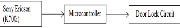
Figure 2.1: Block Diagram of automatic lock system
Figure 2.1 is a block diagram of Automatic Door Lock system. It shows that phone (Sony Ericson (K700i); GSM modem) will receive an SMS from the user, as a consequence a signal will be sent to the microcontroller. Then, the microcontroller will verify the signal whether it is the right person or not to open the door. If the right person sends the SMS, then it will activate the door lock circuit. If the SMS is not from the authorized person then it will keep the door lock.
2.3 Home Security System with GSM