UNIVERSITI TEKNIKAL MALAYSIA MELAKA
EFFECT OF HCl CONCENTRATION, ANODIZATION
VOLTAGE AND TIME ON MICROSTRUCTURE, PHASE AND
PHOTOCATALYSIS ACTIVITY OF TITANIUM DIOXIDE FILM
This report submitted in accordance with requirement of the Universiti Teknikal Malaysia Melaka (UTeM) for the Bachelor Degree of Manufacturing Engineering
(Engineering Materials) (Hons.)
by
NURUL ZAFIRAH BINTI ZULNIZAM B051110356
901028-01-5334
ii
DECLARATION
I hereby, declared this report entitled “Effect of HCl Concentration, Anodization Voltage and Time on Microstructure, Phase and Photocatalysis Activity of Titanium
Dioxide Film” is the results of my own research except as cited in the references.
Signature :………
Author‟s Name : Nurul Zafirah binti Zulnizam
APPROVAL
This report is submitted to the Faculty of Manufacturing Engineering of UTeM as a partial fulfillment of the requirements for the degree of Bachelor of Manufacturing
Engineering (Engineering Material) (Hons.). The members of the supervisory committee are as follow:
………. (Dr. Shahriza binti Ismail)
i
ABSTRAK
Titanium dioksida (TiO2) telah digunakan secara meluas untuk aplikasi
fotopemangkinan. Secara konvensional, TiO2 dihasilkan oleh teknik seperti proses
sol-gel dan kimia wap pemendapan. Walau bagaimanapun, teknik ini sama ada mahal, rumit, atau menghasilkan filem TiO2 dengan sifat-sifat mekanikal yang
lemah. Oleh itu, projek ini adalah bertujuan untuk membuat filem TiO2 dengan
penganodan daripada foil Ti. Parameter penganodan seperti voltan, masa dan kepekatan HCl adalah penting untuk menghasilkan filem TiO2 yang sesuai untuk
aplikasi tertentu. . Objektif projek ini adalah, mensintesis filem TiO2 oleh
penganodan foil titanium, mencirikan filem morfologi TiO2 mikrostruktur dan
permukaan mencirikan sifat-sifat fotopemangkinan filem TiO2. Raman Spectra
menunjukkan anatase dan rutil lebih sukar untuk membentuk dalam HCl elektrolit pada voltan yang lebih tinggi dan masa penganodan yang lebih lama. Bidang Pelepasan Mengimbas mikroskopi elektron Keputusan menunjukkan tiada nanopore diperhatikan dalam mikrostruktur permukaan tidak seragam sampel. Filem TiO2
dikesan foil Ti dan telah disahkan oleh tenaga spektroskopi serakan. Mikroskop imbasan elektron menunjukkan peningkatan voltan dan penganodan gunaan masa, menyumbang kepada kekasaran permukaan yang lebih tinggi pada sampel penganodan. Sampel menunjukkan peningkatan dalam kekasaran permukaan. Didapati sampel penganodan di 10 min dan 5 V menunjukkan prestasi fotopemangkinan lebih rendah berbanding sampel anodized pada masa yang lebih lama (iaitu 20 min). Parameter terbaik untuk filem TiO2 disintesis oleh penganodan
ii
ABSTRACT
Titanium dioxide (TiO2) is used for wide photocatalysis applications.
Conventionally, TiO2 was produced by techniques such as sol-gel process and
chemical vapor deposition. However, these techniques are either costly, complicated, or produces TiO2 film with poor mechanical properties. Hence, this project was
serves to fabricate the TiO2 film by anodization of titanium foil. Anodization
parameters such as voltage, time and HCl concentration were important to produce TiO2 film that suits to particular applications. The objectives of this project is, to
synthesize TiO2 film by anodization of titanium foil, characterize the microstructure,
phase composition and photocatalysis properties of the photocatalysis TiO2 film.
Raman Spectra show anatase and rutile are more difficult to form in HCl electrolyte at higher voltage and longer anodization time. Field Emission Scanning electron microscopy (FESEM) results showed no nanopore observed in the non-uniform surface microstructure of the sample. Nanothickness TiO2 film was detected Ti foil
and was verified by energy dispersive spectroscopy (EDS). Scanning electron microscopy (SEM) result showed an increase of applied voltage and anodization time, contributed to higher surface roughness on the anodized samples. Samples exhibited an increase in surface roughness. It was found the sample anodized at 10 min and 5 V exhibited lower photocatalytic performance as compared to samples anodized at longer time (i.e. 20 min). Hence, the best parameter for TiO2 film
iii
DEDICATION
iv
ACKNOWLEDGEMENT
Bismillahirrahmanirrahim,
I would like to convey my gratitude to Allah S.W.T for giving me strength and Willingness to be able to completed this final year project report. I am indebted with many people during this research. I would like to express my special gratitude, appreciation and thanks to Dr Lau Kok Tee as my first supervisor in this project where he taught me lot of knowledge that is new for me, helping me upon the completion of this research and assist me all the time. Not forgetting my second supervisor Dr.shariza, master student Miss Zurianie, my best friend Mohamad Rafie bin Markam and friends that involved upon completing this report.
v
TABLE OF CONTENT
Abstrak i
Abstract ii
Dedication iii
Acknowledgement iv
Table of Content v
List of Figures viii
List of Table xi
List Abbreviations, Symbols and Numenclatures xii
CHAPTER 1: INTRODUCTION
1.1 Background History and Application 1
1.2 Application 3
1.3 Problem statement 4
1.4 Objective 5
1.5 Scope 5
CHAPTER 2: LITERATURE REVIEW
2.1 General materials properties 6
vi 2.2 Microstructure of titanium dioxide 10
2.2.1 Titanium dioxide (TiO2) nanowire/nanofibers 10
2.2.2 Titanium dioxide (TiO2) nanorods 11
2.2.3 Titanium dioxide (TiO2) nanotubes 12
2.3 Photocatalysis of Titanium Dioxide (TiO2) 13
2.3.1 Reaction Cycles Of TiO2 Photocatalyst 14
2.3.2 Methylene Blue of Titanium Dioxide 15
2.3.3 Photocatalytic effect 16
2.4 Synthesis methods for TiO2 film 17
2.4.1 Anodization 17
2.4.2 Spin coating 19
2.4.3 Physical Vapor Deposition 20
2.2.4 Comparison of anodizing with other method 22
CHAPTER 3: METHODOLOGY
3.1 Introduction 23
3.2 Preparation of Titanium Foil 25
3.3 Anodization of Titanium film 25
3.3.1 Experimental Setup 25
3.3.2 Anodization Parameters 26
3.4 Characterization 28
vii 3.4.2 Raman (Phase) Characterization 28 3.4.3 Photocatalytic Characterization 29
CHAPTER 4: RESULT AND DISCUSSION
4.1 Visual Inspection 30
4.2 Raman Spectra of Anodized Ti Foil 31 4.3 Surface and Cross-sectional Microstructure of Titanium Dioxide Film 39
4.4 Photocatalytic Performance 42
4.4.1 SEM Results for Surface Microstructures of Anodized Ti Foil 45 Before and After Photocatalytic Degradation of Methylene
Blue (MB)
CHAPTER 5: CONCLUSION AND RECOMMENDATION
5.1 Conclusion 48
5.2 Recommendation 50
REFERENCE
viii
LIST OF FIGURES
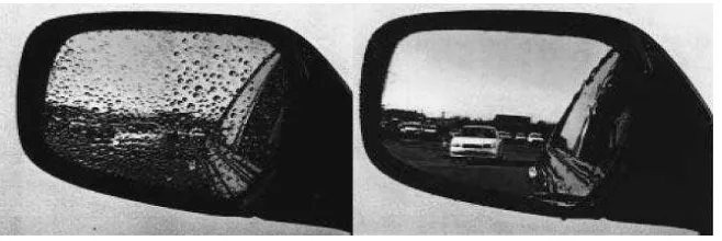
1.1 Anti-fogging effect of automobile side-view mirror: conventiona 2 mirror (left) and TiO2-coated mirror (right)
1.2 Jubilee Church of Rome, Exterior made from Italcementi Concrete 2 Containing TiO2
2.1 Crystal structure of: (a) Rutile, (b) Anatase, and (c) Brookite (Grey 7 coloured atoms – Titanium
2.6 Photocatalysis process and analogy with photosynthesis 13
2.7 Mechanism of Photocatalysis 14
2.8 Structure of methylene blue (MB) 15 2.9 Time dependent photocatalytic degradation UV–vis spectra of TiO2 16
2.10 Schematic Diagram of Anodic Oxidation System 17 2.11 Key stages of spin coating process 19
ix
3.1 Methodology‟s Flow Chart 24
3.2 Experimental Setup for Iodization‟s Methodology 25
3.3 UV box 29
4.1 TiO2 Coated Ti foil Substrate 31
4.2 Raman spectra of sample anodized at 10 min and 5 V in different 32 HCl concentration: 1.0, 1.5, 2.0, 2.5 and 3.0 M
4.3 Raman spectra of sample anodized at 10 min and 10 V in different 33 HCl concentration: 1.0, 1.5, 2.0, 2.5 and 3.0 M
4.4 Raman spectra of sample anodized at 10 min and 12 V in different 34 HCl concentration: 1.0 and 1.5 M
4.5 Raman spectra of sample anodized at 20 min and 5 V in different 35 HCl concentration: 1.0, 1.5, 2.0, 2.5 and 3.0 M
4.6 Raman spectra of sample anodized at 20 min and 10 V in different 36 HCl concentration: 1.0, 1.5, 2.0, 2.5 and 3.0 M
4.7 Raman spectra of sample anodized at 20 min and 12 V in different 36 HCl concentration: 1.0, 1.5, 2.0, 2.5 and 3.0 M
4.8 Raman spectra of sample anodized at 30 min and 5 V in different 37 HCl concentration: 1.0, 1.5, 2.0, 2.5 and 3.0 M
4.9 Raman spectra of sample anodized at 30 min and 10 V in different 38 HCl concentration: 1.0, 1.5, 2.0, 2.5 and 3.0 M
4.10 Raman spectra of sample anodized at 30 min and 12 V in different 38 HCl concentration: 1.0 M
4.11 FESEM image of the surface microstructure a) 10000 magnification 39 b) 50000 magnification
x 4.13 Surface image a) 10000 magnification b) Cross section 50000 41
magnification of sample 20 min, 2.5 M and 5 V
4.14 UV-vis results of methylene blue degradation after UV exposure at 43 0 to 120 min, obtained from photocatalytic reaction with sample
anodized at 10 min and 5 V in 2.5 M HCl min
4.15 UV-vis results of methylene blue degradation after UV exposure at 43 0 to 120 min, obtained from photocatalytic reaction with sample
anodized at 20 min and 5 V in 2.5 M HCl min
4.16 UV-vis results of methylene blue degradation after UV exposure at 44 0 to 120 min, obtained from photocatalytic reaction with sample
anodized at 10 min and 10 V in 2.5 M HCl min
4.17 UV-vis results of methylene blue degradation after UV exposure 44 at 0 to 120 min, obtained from photocatalytic reaction with sample
xi
LIST OF TABLES
1.1 Applications of TiO2 3
2.1 Crystallographic and Physical Properties of Rutile, Anatase & 8 Brookite.
2.2 Raman peak positions for rutile and anatase 9 2.3 The advantages and disadvantages of PVD 21 2.4 Comparison of anodize, spin coating and PVD methods 22
3.1 List of Available Sets of Parameters 26
4.1 SEM images of surface microstructures of anodized samples 45 before and after photocatalytic degradation of MB 10000×
magnification
4.2 SEM images of surface microstructures of anodized samples 46 before and after photocatalytic degradation of MB 5000×
xii
LIST OF ABBREVIATIONS, SYMBOLS AND
NOMENCLATURE
CO - Carbon Monoxide
Cr - Chromium
EDS - Energy Dispersive Spectroscopy
Fe - Iron
xiii NO2 - Nitrogen Dioxide
NO - nitric Oxide
PVD - Physical Vapor Deposition
S - Sulfur
SEM - Scanning Electron Microscopy SO2 - Sulphur dioxide
Ti - Titanium
Å - Angstrom
λ - Wavelength
ε - Strain
ω - Omega
α - Alpha
β - Beta
γ - Lambda
e− - Negative electron
1
CHAPTER 1
INTRODUCTION
1.1 Background History and Application
Photocatalyst can be in form such powders and coating. In 1938 there are a report on photobleaching of dyes where it was happen when the UV absorption produces an active oxygen species on the TiO2 surface (Hashimoto et al; 2005).
In 1970's, TiO2 was used to produce hydrogen gas (H2) using photocatalytics. TiO2
was used in form of electrode where it was contributed to the production sites of the H2 and O2 gases, and then recombine back into water (Hashimoto et al; 2005). By the
mid 1980‟s, H2 production by TiO2 photocatalyst became unattractive as other
semiconductors were better suited for future research and development (Hashimoto et al; 2005).
In early 1990s, TiO2 film photocatalysis have been investigated under weak UV light
for photocatalytic cleaning, antibacterial, and hydrophilic characterization. Photocatalytic antibacterial effect decomposition reaction of photocatalytic can be applicable to microorganisms. In fact, Escherichia coli (E. coli) cells can completely eliminated by photocatalysis of TiO2 after about one week under a UV irradiation of
2 Figure 1.1: Anti-fogging effect of automobile side-view mirror: conventional mirror (left) and TiO2
-coated mirror (right) (Hashimoto et al; 2005).
The design of nanostructure of TiO2 was introduced in 21st century (Hashimoto et al.;
2005). Sensitivity of TiO2 was extended to visible light range by substituting. Cr, Fe
or Ni for Ti site, but the method was not accepted wider due to the lack of reproducibility and chemical stability (Hashimoto et al; 2005). Commercial cements containing TiO2 that was introduces to reduce surface pollution. The notable
Italcementi‟s projects is the Jubilee church in Rome, shown in Figure 1.2 and constructed using white cement containing TiO2 (Hashimoto et al; 2005).
3
1.2 Applications
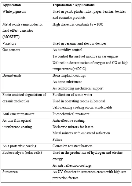
Table 1.1: Applications of TiO2 (Abdullah & Sorrell; 2010)
Application Explanation / Applications
White pigments Used in paint, plastic, inks, paper, leather, textiles and cosmetic products
Metal oxide semiconductor field effect transistor (MOSFET)
High dielectric constants (ε = 100)
Varistors Used in ceramic and electric devices Gas sensors As humidity control
To control the air/fuel mixture in car engines Utilized in determination of oxygen and CO at high temperatures (>600˚C)
Biomaterials Bone implant coatings As bone substituent
As reinforcing mechanical support Photo-assisted degradation of
organic molecules
Purification of waste water
Used in operating rooms in hospital Self-cleaning coating on car windshields Anti cancer treatment Photochemical treatment
As thin film optical interference coating
Antireflective coating Dielectric mirrors for lasers
Metal mirrors with enhanced reflection Filters
As a protective coating Corrosion resistant barriers
Photocatalysts (solar cells) Used in the production of hydrogen and electric energy
As anti-reflection coatings
4 Food Foodstuff, food colouring (E-171)
Pharmaceuticals As tablet coating, toothpaste
As catalysts Selective reduction of NOx to N2, Hydrogen
production by gas shift production, CO oxidation by O2, H2S oxidation to S, Reduction of SO2 to S by
CO, NO2 storage
Used in fluxes and ceramics Raw materials
Li-based batteries Anatase form is used as anode material Electrochromic devices Thin film coating
1.3 Problem Statement
Photocatalytic degradation is an effective way of transforming organic pollutants into harmless end products at ambient conditions using light and photocatalyst. TiO2
shows different characteristics and properties in different phases. Anatase, brookite, and rutile are three different phases (crystalline forms) of TiO2. There have different
thermal stability, crystal size, and reactive surface area. Surface area and microstructure of TiO2 easily affect its photocatalysis properties (Hanaor & Sorrell;
2010). An increases of total surface area increases the pollution reduction potential of TiO2 as it increases the surface area for reaction with pollutants (Hanaor & Sorrell;
2010).
Suitable processing method and parameters are important to produce TiO2 film that
suits to particular applications. Nevertheless, the choice of synthesis method is determined by cost control, quality of product, safety issues, etc. Current available production synthesis such as physical vapour deposition method is costly or involving complicated process (Erol et al; 2014). Anodization is a less expensive electrochemical method to produce TiO2 film. TiO2 film synthesized by this
5 does not flake off in highly stressed areas and has increase in fatigue strength increase of 15-20% due to its homogeneous surface treatment.
1.4 Objective
The purpose of this research is to synthesize TiO2 thin film on titanium substrates
using anodization method. Below are the specific objectives for this research;
a) To synthesize TiO2 film by anodization of titanium foil.
b) To characterize microstructure and phase composition of the TiO2 film.
c) To characterize photocatalysis property of the TiO2 film.
1.5 Scope
Investigation of the relationship between anodization parameters, phase composition and microstructure of TiO2 film were conducted. Effect of three anodization
parameters: voltage, anodizing duration and HCl acid concentration were studied. Scanning Electron Microscopy (SEM) and Field Emission Scanning Electron Microscopy (FESEM) are used to characterize the microstructure of TiO2 film.
Raman spectroscopy is used to characterize phase composition of the TiO2 film. The
6
CHAPTER 2
LITERATURE REVIEW
The literature review of the titanium dioxide (TiO2) was discussed in this chapter.
The TiO2 material and its general physical properties and crystallography is
discussed in the first section. Next, the photocatalyst properties are reviewed in relationship to TiO2 is being used as the thin film coating on titanium. Anodization is
discussed and compared with other fabrication techniques.
2.1 General Materials Properties
TiO2 exists in three different polymorphous structures: Anatese, rutile, and brookite.
Anatase and brookite appear as metastable phases compared to more stable rutile phase (Hanaor & Sorrell; 2010).
7 Figure 2.1: Crystal structure of: (a) Rutile, (b) Anatase, and (c) Brookite (Grey coloured atoms –
Titanium, Red coloured atoms – Oxygen) (Pavemaintenance; 2014) (a)
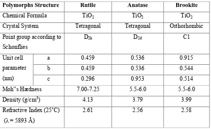
8 Table 2.1: Crystallographic and Physical Properties of Rutile, Anatase & Brookite. (Nakaruk; 2010)
Polymorphs Structure Rutile Anatase Brookite
Chemical Formula TiO2 TiO2 TiO2
Crystal System Tetragonal Tetragonal Orthorhombic Point group according to
Schonflies
D2h D2d C1
Unit cell parameter (nm)
a 0.459 0.536 0.915
b 0.459 0.536 0.544
c 0.296 0.953 0.514
Moh‟s Hardness 7.00-7.25 5.5-6.0 5.5-6.0
Density (g/cm3) 4.13 3.79 3.99
Refractive Index (25˚C) (λ = 5893 Å)