PARALLEL VISUALIZATION WITH GLOBAL DATA
BASED DISTRIBUTED CACHE FRAMEWORK
ZHAO Di*
College of Resources and Environment and Tourism, Hunan University of Arts and Science, Changde 415000, Hunan China, E-mail: [email protected]
KEY WORDS: parallel visualization; global data; render; distributed cache; network
ABSTRACT:
Visualizing the global data smoothly is a challenge to the present software and network technology, such as simulating global weather phenomena or global geological environment. In this paper, we devised an effective solution system to view global data at a real-time rendering pleasing frame rate based parallel mode. In software, we applied the open-source Visualization ToolKit (VTK) and the additional functionality of ParallelVTK. In network, we propose a centrally controlled cache system with distributed cache storage framework. The cache control server can manages a list of all contents cached by multiple cache servers and it can provide real-time requested content to the user. Additionally, it can reduce network traffic between the core network and the access network. We tested issues of our system and describe a prototype system. As a result of evaluation of the system, we have made it clear that our system architecture is effective to the global data.
* Corresponding author. Foundation item: Project supported by Doctoral Research Start-funded of HUAS, 13101036.
1. INTRODUCTION
Computer visualization is an important tool for data analysis and presentation in computational and geographic sciences, where it is used to effectively extract and convey information contained in large datasets[1,2]. Our goal is mainly to effectively visualize the global data at a satisfying frame rate, it is need delighted to the eye. In order to process such the large data sets, we introduce an open source and parallel visualization framework. This solution is not restricted by the hardware, since the transfer time of the data set on a single SATA drive is less than desired results[3,4].
Simultaneity, we also apply the distributed cache technology in the network. The number users increased predict that the number of requests for visualization from users to web servers will increase at the same time. Therefore, the problems such as cessation of service may occur and network traffic will increase. To overcome such problems, we introduce a cache server in the network to serve contents. It can help to restrain the increase in requests to web servers by delivering contents from the cache server. Consequently, traffic in the core network is reduced.
In this paper, we propose the open source and parallel visualization framework and distributed cache system to apply in the global data network accommodating millions users. We also explain the prototype of our system and evaluate whether it is suitable for global data or not.
2. PARALLEL VTK
The task of visualizing the global datasets presents the challenge of overcoming the high disk I/O required to yield pleasing frame rates. In order to facilitate this and make efficient use of the Storage Area Network (SAN), a scalable and parallel framework was used. The Visualization ToolKit (VTK) and extension, Parallel VTK, offer an open source and multi-platform solution[5-7]. Parallel VTK builds on top of the
multi-scale platform interface (MPI) of choice for parallel computation. Parallel VTK offers three distinct parallel models. For extremely large, single time-step data, data parallelism divides the data among the processes to be rendered[8]. Each time-step in the global dataset is actually small enough that one process is quite capable of rendering the entire scene easily.
The second parallel option, pipeline parallelism, makes data parallelism less useful. It is intended for large, time-varying datasets and is relevant for use cases. It allows one process to perform the disk I/O while another process can do the rendering. These processes can be performed concurrently, so process 1 can start reading in time step 2 while process 2 is still rendering time step 1. Communication is performed by input/output port classes that abstract the MPI sends/receives.
The final parallel model is task parallelism. This allows for a step in a VTK data flow to be performed in parallel. We can use this functionality to read in time steps of the data series in parallel. Rendering the global data files does not require more than one process, since it is overpowered by the disk I/O bottleneck incurred from reading in the data.
3. DISTRIBUTED CACHE SYSTEM
The introduction of cache servers in network is a popular way to reduce the processing load of web servers as the number of content requests increase, and to reduce network traffic in core networks[9,10]. The cache servers help to control the number of requests for contents to the web server by delivering contents from the cache servers in the access network. This also works to restrain the increase in the processing load of the web servers. Furthermore, by reducing the number of requests to the web servers, network traffic between the access and core networks is reduced. However, the processing performance of the cache server will be a problem when it receives requests from hundreds of thousands of users.
To overcome the above issue, multiple cache servers have
International Archives of the Photogrammetry, Remote Sensing and Spatial Information Sciences, Volume XL-2/W1, 2013 8th International Symposium on Spatial Data Quality , 30 May - 1 June 2013, Hong Kong
been introduced [11,12]. In this case, each cache server only processes requests from users who are connected to it. When each cache server caches contents independent of other cache servers, the cached contents are limited due to limited cache space. In addition, since the requests for contents from all users are processed by multiple cache serves, the number of requests processed by each cache server is small. Therefore, the hit ratio, which is the percentage of the existence of cached contents to
The cache system where multiple cache servers cooperate to reply the contents requested from users is called a distributed cache system.
4. IMPLEMENTATION ISSUE
4.1 VTK Visualization Implementation
A VTK visualization consists of a visualization pipeline. Traditionally a pipeline starts with a data source. In this case the data source is a vtkRectilinearGrid. A rectilinear grid is a 3-dimensional grid of data points with a fixed number of values in the x, y, and z directions. It also allows for the divisions in each coordinate direction to be arbitrary.
The input and output ports are VTK classes which allow processes to send and receive data sources. These processes could lie anywhere in a MPI environment, so they are most likely on separate machines. This communication method will allow the visualization to take advantage of pipeline and task parallelism. vtkInputPorts are designed to be “single source”, so only parameters to a data set can be altered after the source is pushed across the network at the first time.
Next, the data source is passed to a contour filter. Contour filters perform isosurfacing of the data. A rectilinear grid is just a 3-dimensional array of values and not a traditional 3-dimensional object that is part of a visualization scene. Given a certain threshold, the contour filter will convert the data source to the desired polygonal representation viewing.
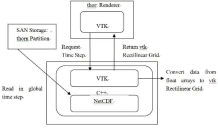
Finally, VTK pipelines are often closed with a data mapper and an actor. The data mapper converts the object representation to a representation that the graphics card will better understand. Actors are traditional in scene graphs to represent objects and their appearance. All actors are added to the window to create the entire scene. A view of the mapping of the visualization pipeline onto the cluster is shown in Figure 1.
Figure 1: Flow of global data to VTK format. Since reading in each time step from disk presents the largest time consumption, we identified this task for parallelization. Isosurfacing and rendering each time step is relatively fast and these tasks will be performed as the rendering nodes. The
remaining processes will be referred to as reader nodes. All communication between the renderer and the readers is performed through the vtk input/output ports.
All processes have access to a shared VTK MPIC ontroller object that allow the process to identify its index. These indices are used to set tags in the input and output port objects. The techniques allow the renderer to actively prepare an input port to request the next sequential time step from the corresponding process that lies on the machine with the time step on its SAN partition. manages a list of all contents cached by multiple cache servers. The list of contents is comprised of URLs that are cached by cache servers in the cache system and a cache server ID that caches the content.
The basic operation of DCCS is as follows. A cache server receives a request for content from a user who has searched for the requested content from all of the content that the cache server caches. If it has the requested content, the cache server delivers it to the user who requested the content from the cache server. On the other hand, if the requested content is not in the cache server, the cache server forwards the request to the cache control server. Then the cache control server that received the content request from the cache server retrieves the list of contents to determine whether the requested content is cached in the cache system or not. If there is a cache server that caches that particular content, the cache control server sends an instruction message to that cache server to forward the content to the cache server that first requested the content. The cache servers, the cache control server sends the instruction message to the cache server with the lowest load to forward the content. Therefore, the load balancing of the cache server is possible in our system. In addition, to maintain correspondence of the lists of contents in the cache control server with the list of contents cached by the cache servers in the DCCS, the cache server must send the URL that the cache server deleted. Therefore, the processing load of the cache control server may increase due to processing the URL messages from all cache servers
The prototype system is composed of one cache cooperation
International Archives of the Photogrammetry, Remote Sensing and Spatial Information Sciences, Volume XL-2/W1, 2013 8th International Symposium on Spatial Data Quality , 30 May - 1 June 2013, Hong Kong
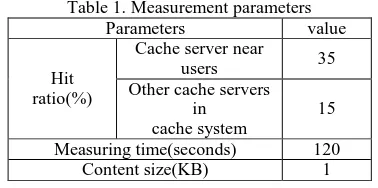
router, three cache control servers, six web servers and six cache servers. The cache control servers, the web servers, and the cache servers are connected through the cache cooperation router. The cache control servers and the cache cooperation router affect the performance of the DCCS. Therefore, with the prototype system, we measured CPU load in each cache control server when changing the number of cache control servers. We also measured the load of the cache cooperation router when registering the list of contents cached in the system. The measurement parameters are in Table 1. The hit ratio of a cache server is stated by the results of measurement in a real
Figure 2 shows the relation between the number of requests from users and the CPU load of the cache control servers when there were one, two, and three cache control servers. As seen in Figure 2, with one cache control server, the CPU load of the cache control server reaches nearly 100% when the total requests from users becomes 2,000 requests per second and the performance of the cache control server reaches the limit. However, the CPU load of the cache control server decreased in proportion to the increase in the number of cache servers when the number of cache servers was two or three.
Figure 2. CPU load of cache control server
Figure 3. CPU load of cache cooperation router
5.3 Performance of cache cooperation router
Next, we measured the load of the CPU. This CPU registers the hash value sent from the cache control servers. The measurement results are in Figure 3. As seen in this figure, the
CPU load falls when the user request ratio reaches 2,000 requests per second in the case of one cache control server. This is because the performance of the cache control server reaches a limit, and the cache control server cannot transmit the URLs of contents to the cache cooperation router.
Similarly, CPU load increased in proportion to the increase
According to the investigation results, the number of average pages that one broadband user refers to per month is 2,000. If we assume each page is composed of 10 sub-components on average, each user sends 20,000 requests a month. In this case, the average ratio of the request from one user is about 0.0077 requests per second. In an access network accommodating one million users, 7,700 requests are sent each second.
As one cache control server can process about 2,000 requests, as seen in the measurement results, 7,700 requests are cooperation router is about 4,000. Therefore, the prototype system can be applied to a network where half-million users are accommodated.
6. CONCLUSION
We present a solution for visualizing global data sets in a real-time high performance environment, which can also be easily modified for use on commodity hardware. Likewise, the result can be viewed in real-time while being rendered or can be saved for reuse at a later time. Also, we apply distributed cache technology in parallel visualizing network and evaluated the prototype system. We demonstrated that the system can be applied to large-scale systems accommodating one million users from the point of view of average request processing.
REFERENCES
[1] Grundy E., Jones M. W., Laramee R. S., Wilson R. P., Shepard E. L. C.: Visualisation of sensor data from animal movement. Comput. Graph. Forum 28, 3 (2009), p. 815-822.
[2] Graphics of Large Datasets: Visualizing a Million (Statistics and Computing), 1 ed. Springer, (2006). [3] Blaas J., Botha C. P., Grundy E., Jones M. W., Laramee R.
S.: Smooth graphs for visual exploration of higher-order state transitions. IEEE Transactions on Visualization and Computer Graphics 15, 6 (2009), 969–976.
[4] Blaas J., Botha C., Post F.: Extensions of parallel coordinates for interactive exploration of large multi-timepoint data sets. IEEE Transactions on Visualization and Computer Graphics 14 (2008), 1436–1451.
[5] M. Isard, M. Budiu, Y. Yu, A. Birrell, and D. Fetterly. Dryad: distributed data-parallel programs from sequential building blocks. In EuroSys’07, (2007), p. 59-72.
[6] K. Shvachko, H. Kuang, S. Radia, and R. Chansler. The hadoop distributed file system. Mass Storage Systems and Technologies, IEEE / NASA Goddard Conference on, 0:1–10, (2010).
[7] “Cache Array Routing Protocol and Microsoft Proxy Server
International Archives of the Photogrammetry, Remote Sensing and Spatial Information Sciences, Volume XL-2/W1, 2013 8th International Symposium on Spatial Data Quality , 30 May - 1 June 2013, Hong Kong
version 2.0”, http://www.microsoft.com/technet/archive/proxy/prxcarp. ms px
[8] Web Advertising Bureau, Japan Advertisers Association, “Recent viewing performance in Web gazette meeting for the study," http://www.wab.ne.jp/pdf/data_040113.pdf, (2005).
[9] M. Tang, B.-S. Lee, X. Tang, and C. K. Yeo. The impact of data replication on job scheduling performance in the data grid. Future Generation Comp. Syst., (2006), p. 254–268.
[10] Q. Wei, B. Veeravalli, B. Gong, L. Zeng, and D. Feng. Cdrm: A cost-effective dynamic replication management scheme for cloud storage cluster. In CLUSTER’10, (2010), p. 188–196.
[11] C. L. Abad, Y. Lu, and R. H. Campbell. Dare: Adaptive data replication for efficient cluster scheduling. In CLUSTER, (2011), p. 159-168.
[12] Qu H., Chan W.-Y., Xu A., Chung K.-L., Lau K.-H., GUO P.: Visual analysis of the air pollution problem in hong kong. IEEE Transactions on Visualization and Computer Graphics 13, 6 (2007), 1408 –1415.
International Archives of the Photogrammetry, Remote Sensing and Spatial Information Sciences, Volume XL-2/W1, 2013 8th International Symposium on Spatial Data Quality , 30 May - 1 June 2013, Hong Kong