A COMPARISON BETWEEN ACTIVE AND PASSIVE TECHNIQUES FOR
UNDERWATER 3D APPLICATIONS
G. Bianco*, A. Gallo, F. Bruno, M. Muzzupappa
University of Calabria, Department of Mechanical Engineering, Rende (CS) - Italy
(gianfranco.bianco, alexgallo, f.bruno, muzzupappa)@unical.it
KEY WORDS: Stereo vision, underwater imaging, dense reconstruction, structured-light
ABSTRACT:
In the field of 3D scanning, there is an increasing need for more accurate technologies to acquire 3D models of close range objects. Underwater exploration, for example, is very hard to perform due to the hostile conditions and the bad visibility of the environment. Some application fields, like underwater archaeology, require to recover tridimensional data of objects that cannot be moved from their site or touched in order to avoid possible damages. Photogrammetry is widely used for underwater 3D acquisition, because it requires just one or two digital still or video cameras to acquire a sequence of images taken from different viewpoints. Stereo systems composed by a pair of cameras are often employed on underwater robots (i.e. ROVs, Remotely Operated Vehicles) and used by scuba divers, in order to survey archaeological sites, reconstruct complex 3D structures in aquatic environment, estimate in situ the length of marine organisms, etc. The stereo 3D reconstruction is based on the triangulation of corresponding points on the two views. This requires to find in both images common points and to match them (correspondence problem), determining a plane that contains the 3D point on the object. Another 3D technique, frequently used in air acquisition, solves this point-matching problem by projecting structured lighting patterns to codify the acquired scene. The corresponding points are identified associating a binary code in both images. In this work we have tested and compared two whole-field 3D imaging techniques (active and passive) based on stereo vision, in underwater environment. A 3D system has been designed, composed by a digital projector and two still cameras mounted in waterproof housing, so that it can perform the various acquisitions without changing the configuration of optical devices. The tests were conducted in a water tank in different turbidity conditions, on objects with different surface properties. In order to simulate a typical seafloor, we used various concentrations of clay. The performances of the two techniques are described and discussed. In particular, the point clouds obtained are compared in terms of number of acquired 3D points and geometrical deviation.
* Corresponding author.
1. INTRODUCTION
3D scanning techniques are widely used in many applications related to Cultural Heritage and they can operate in long-range acquisition to reconstruct buildings, archaeological sites (Guidi, 2009; El-Hakim, 2004), or in close-range to acquire 3D models of statues (Fontana, 2002), bas-reliefs (Cignoni, 1997), etc. In underwater environment, 3D reconstructions of shipwrecks or submerged archaeological sites is a challenging issue, because of the hostile conditions and the bad visibility, but nowadays the trend is to preserve in situ the underwater heritage, in order to avoid possible damages according to the guidelines of Unesco (Unesco, 2001) that prescribes to not remove the artefacts from the site.
Imaging techniques and appropriate equipment are employed for the underwater exploration done by scuba divers and robots like ROVs (Remotely Operated Vehicles) and AUVs (Autonomous Underwater Vehicles). Underwater imaging is seriously compromised by scattering and absorption in the medium, which decrease image contrast and attenuate light intensity (Gupta, 2008) with consequent loss of details and colour alteration. Because of these limitations, many solutions to improve image quality in presence of turbidity and reduce the scattering have been investigated (Jaffe, 1990; He, 2004; Schechner, 2004). For example, sophisticated laser-based methods employ narrow beams to reduce the degrading effect caused by the scattering component that appears in the overlapped volume of the device Field-Of-Views (FOVs)
(Moore, 2001). Passive techniques don’t use structured-light, but are based on multiple acquisition, allowing to obtain 3D reconstructions from a set of overlapped images. Passive methods are widely applied in underwater due to the less-complicated system needed to acquire the scene, i.e. seabed mapping (Leone, 2006) or survey of archaeological sites (Drap, 2007). Common features are detected in an image sequence and the correspondence among them is established in order to triangulate the positions of the points belonging to the object. In the case of stereo vision (a pair of images), the correspondence problem can be solved with both passive and active approaches. In the first case, two images of the scene are captured with environment light and common features have to be detected on the textured pictures. In the latter case, a sequence of patterns is projected on the surface object to codify the scene in both views. Thus, the correspondence is independent from the texture of the object.
In this work, we present a comparison between two stereo techniques using passive and active approach for 3D reconstructions in underwater environment. 3D acquisitions have been conducted in a water tank, changing the turbidity level at every attempt. A 3D scanner, composed by two still cameras and a digital projector lodged in water-proof housings, is used to acquire a set of image to be elaborated. The experimental setup does not change for the two techniques, thus we can compare the results of 3D acquisitions obtained with the same camera positions, optical devices, calibration and working distance. In particular, the same calibration procedure is International Archives of the Photogrammetry, Remote Sensing and Spatial Information Sciences, Volume XXXVIII-5/W16, 2011
performed in water for both techniques, and the intrinsic (focal length, principal point, optical distortions) and extrinsic parameters (relative positions of cameras) are calculated and compared with the ones obtained in air. Finally, the acquired point clouds are compared in terms of number of acquired 3D points and geometrical deviation.
This paper is structured as follows: after a preliminary introduction, Section 2 presents an overview of 3D imaging techniques used in underwater environment. Section 3 describes the stereo techniques used in this work for 3D underwater reconstructions. The 3D system and the experimental tests are presented in Section 4 and in Section 5 the results and comparisons are illustrated. Finally, in the last section we report discussions and conclusions.
2. UNDERWATER 3D TECHNIQUES
3D imaging techniques used in underwater environment are classified in passive and active techniques, depending if they employ environment or artificial light source, respectively. Passive techniques or photogrammetric techniques are based on multiple acquisitions of the scene taken by different viewpoints, with movie or still camera, so they work with the whole FOV of the optical sensor. In these techniques, artificial lights (lamps and spotlights, for example) are used just to illuminate the scene and are not exploited in the triangulation of the 3D points. Stereo systems use two digital cameras to capture the scene and may be installed on underwater robots (Allias, 2007) or used by scuba divers (Menci, 2010) in applications like seabed mapping and in situ estimation of the length of marine organisms (Harvey, 1995). The structure from motion technique uses an image sequence acquired by a moving camera. It involves the extraction and tracking of a sparse set of features in an image sequence, and the estimation of their 3D positions using multiple views (Saito, 1995). The multiple-camera system, with overlapping FOVs, allows for a much wider FOV for panoramic views, photo-mosaics, 3D motion estimation and positioning (Firoozfam, 2003). 3D underwater active systems are usually suitable for long-range acquisition (Jaffe, 1990) because they make use of coherent light (laser) that allows a better light propagation in scattering medium. 3D active optical techniques are based either on the triangulation principle or on time delay (time-of-flight and interference) of the laser light (Remondino, 2006).
In the first case, a light source projects structured light (sheet, narrow beam) on the object and an image sensor acquires the light reflected from another location; the 3D points are acquired by knowing the relative position of two devices (i.e.: source and receiver). The time-of-flight techniques operate by transmitting short pulses of light and detecting the light reflected from objects within the receiver FOV. Range information is obtained by measuring the time delay between the transmitted and received light pulses. Finally, holography provides the three-dimensional coordinates by the interference between two coherent waves propagating from the object and a reference wave: the geometrical shape of an object is related to the whole-field measure of the optical phase. Underwater techniques based on triangulation and time-of-flight use a sheet light or a narrow beam. The single sheet projection is useful in several applications like underwater navigation (Dalgleish, 2004) and mapping of underwater archaeological sites (Roman, 2010). Using the forward movement of the AUV, a stripe of light can provide the map of a seabed (Jaffe, 1988). Underwater holography is used in marine biology in order to study the
plankton, because it allows small-scale 3D reconstruction with high accuracy (Hobson, 2002).
3. ACTIVE AND PASSIVE STEREO TECHNIQUES
In this Section we explain methods and algorithms on which the two stereo techniques used in the underwater experimentation are based. The calibration of an optical device and of a stereo system is also described.
3.1 3D stereo reconstruction
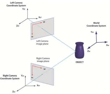
Given two images acquired from slightly different viewpoints, a stereo matching algorithm tries to identify corresponding points in both images related to the same scene point (Figure 1). Common points must be extracted (i.e. with SIFT operator (Lowe, 2004) in the overlapped images, in order to solve the so-called correspondence problem, that allows to match these points in corresponding images.
Knowing these correspondences and the scene structure, the 3D world coordinates or each image point can be reconstructed by triangulation. To simplify the search, the images are commonly rectified, putting the stereo rig in a more convenient configuration (standard form), in which corresponding points are constrained on the same scan-line (epipolar constraint), so that the stereo problem is reduced to a one-dimensional search along each epipolar line. The disparity, where the depth is encoded, represents the distance between x-coordinates or a pair of correspondent points in left and right images. Finding a pair of correspondent points is not so trivial. Since the scene is acquired from different points of view, it is possible to find false correspondences due to occlusion, radiometric distortion and perspective distortion.
Figure 1: Stereo correspondence in left (ml) and right (mr) images of a 3D point w on the object.
3.2 Passive stereo
In general, stereo algorithms are classified in local and global methods (Scharstein, 2002) and both categories assume that the scene is piecewise smooth. Local algorithms implicitly model this assumption, computing the similarity of colour or intensity of neighboring points within a support window (correlation window), while global methods explicitly incorporate smoothness assumptions, computing all the disparities at the same time by minimizing an energy function with techniques such as graph cuts, belief propagation, dynamic programming (Scharstein, 2002). Local algorithms are typically faster than global approaches and more suited for hardware/real-time International Archives of the Photogrammetry, Remote Sensing and Spatial Information Sciences, Volume XXXVIII-5/W16, 2011
implementation, but in most cases they are outperformed in terms of the accurateness by global approaches.
In our work, the MVS (Multi-View Stereo) algorithm PMVS2 (Furukawa, 2007) has been used to solve the correspondence problem. This algorithm estimates the surface orientation while enforcing the local photometric consistency, which is important to obtain accurate models for low textured objects or with images affected by blur due to turbidity in underwater environment. PMVS2 is a patch-based MVS algorithm that outputs a dense collection of small oriented rectangular patches (a local tangent plane approximation of a surface), and consists of a procedure of matching, expanding, and filtering. In the first matching step, a sparse matching algorithm based on Harris and DoG (Difference-of-Gaussian) operators, detects and matches a collection of reliable point features satisfying the epipolar constraint, sparsely distributed in each image. In the expansion step, these initial matches are propagated to neighboring pixels to obtain a dense collection of patches: then, in the filtering step, false matches are deleted using the visibility constraint. Ideally, the number of 3D points that it is possible to reconstruct with these techniques is equal to the number of correspondent pixels in the image pair.
3.3 Active stereo
Whole-field structured-light techniques are based on the projection of white light patterns. Different patterns as gray-code bands, sinusoidal fringes, grids, etc. are projected on the surface and the scene is taken by a camera placed in a known position to calculate the triangulation (Salvi, 2004).
The active stereo technique that we use in this work is based on the codification of a set of black/white patterns projected on the object by a digital projector. The use of the gray-code makes the matching between correspondent points in the stereo pairs more effective (Barone, 2004). The object is illuminated by a set of n temporally encoded patterns of black/white bands (Figure 2), with width progressively halved, so that n images are captured. A binary code (0, 1 with n bit) is assigned to each point in the camera frame, and the values 0 and 1 are associated to intensity levels, i.e. 0=black and 1=white. This procedure allows to codify 2n-1 lines defined as crossing zones between white and black bands. Moreover, coded patterns with a bandwidth of 4 pixels shifted in steps of 1 pixel for a total of 4 pattern positions are used to exploit the minimum resolution of the projector. By projecting both horizontally and vertically striped coded patterns, a double code is assigned to the intersection points through the horizontal and vertical lines. So this procedure allows to codify automatically each point of the object surface. In this work a set of 8 vertical and 8 horizontal patterns (8-bit code) is used for gray-code.
Figure 2. (left) Example of three binary patterns with an associated 3-bit code that allows to distinguish 8 stripes; (right) examples of code shifting patterns.
Other 4 + 4 patterns are projected for vertical and horizontal code shifting, respectively, with a bandwidth of four pixels (Figure 2). The current projector resolution is 800x600 points that allows us to codify 799 lines x 599 lines = 478.601 points. The projector is only used to establish the correspondences and is not involved in the triangulation, so it is not required to calibrate its optics. In contrast to traditional passive approaches, this technique does not rely on images with consistent textures, because each point on the object surface is precisely identified thanks to a double binary code.
3.4 Calibration
A calibration procedure is needed to compute the intrinsic (focal length, coordinates of the principal points, radial and tangential distortions) and extrinsic (positions and orientations with respect to an absolute reference system) parameters of the cameras. In particular, these parameters are obtained using Camera Calibration Toolbox of Bouguet (Bouguet, 2011). The calibration is performed with a planar object point array (a black/white checkerboard pattern) placed in several positions and acquired by the two cameras. The parameters of each camera are obtained by correlating the coordinates of known markers located on the checkerboard with the corresponding coordinates on the image plane. For each position, an iterative process solves the correlation equation and provides, separately, the intrinsic and the extrinsic parameters of each camera. The stereo calibration is based on correspondence between the points of the checkerboard in the two camera images. It consists of an overall optimization problem solving, that minimizes the re-projection error between camera planes. The optimized parameters are both intrinsic and extrinsic of each camera and extrinsic of the stereo pair.
Figure 3. Coordinate systems of the cameras and the object.
4. EXPERIMENTATION
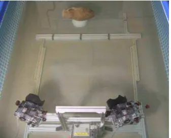
A 3D system has been designed, composed by a digital projector and two still cameras, so that it can perform the various acquisitions without changing the configuration of optical devices. The tests were conducted in a water tank in different turbidity conditions, on objects with different surface properties.
4.1 Underwater 3D system
Two cameras Nikon D200, with a CCD (Charge Coupled Device) sensor size of 23.6x15.8 mm and resolution of 3872x2592 pixels and an AF-Nikkor 35mm lens, are used to acquire the scene. The projector Mitsubishi PK20 is characterized by a very small size (123x48x97 mm), an acceptable resolution of 800x600 pixels and a brightness of 25 lumens. The three optical devices are lodged in waterproof housings and fixed on an aluminium support (Figures 4, 5). A dome port is mounted on the camera housing to reduce the refractive effects at the air-water interface (Edge, 2006). Appropriate connections allow us a remote control of the projection and acquisition, by the means of a PC.
4.2 Calibration system
Calibration is performed in air and in water tank, to evaluate and compare the results of intrinsic and extrinsic parameters in both conditions. As shown in Table 1, the principal point does not present evident changes, while the focal length in water is greater than the one in air of about 13%. This value increases of 25% if we use a flat port in front of the objective, while it decreases to 1% if a 20 mm wide-angle lens is mounted. The maps of optical distortions (radial and tangential component) show that, in the image centre where the object to be captured is present, deviations are very small (about 3 pixel), and they are corrected by stereo algorithm during the image rectification. In order to evaluate the effectiveness of the underwater calibration, we considered the re-projection error for each corner point of the checkerboard, defined as the distance between the points of the actual image, and those computed from the back projection of the ideal checkerboard. The error dispersion are Gaussian-distributed and the values obtained in water are comparable with the ones obtained in air. The calibration of the stereo systems evidences that there is a limited difference (1%) between the extrinsic parameters (R rotation matrix and T translation vector), in air and in clear water.
Parameters (mm) Air Water
Focal length 37.556 42.426
Principal point px
py
11.078 11.078 7.575 7.423
Table 1. Mean values of intrinsic parameters of left and right camera in water and air.
4.3 Underwater acquisition
An amphora and a mask (Aeolus) are the earthenware objects of used in the experimentation (Figure 6). Two images are acquired for the passive stereo technique and 50 images for the active stereo in air and in water (Figure 7). Different turbidity conditions are obtained by dissolving clay powder in the water. We have decided to use in water the 35mm lens because its FOV allows to acquire the entire objects at a working distance of about 1m.
4.4 3D reconstruction
Subsequently, the acquired images have been processed with the two stereo techniques to obtain the point clouds of the objects. For active stereo, the software for 3D reconstruction is provided by Scansystems (Scansystems, 2011). From the 50
image pairs and the calibration data, we give automatically the 3D point cloud of the scene. Regarding passive stereo, as mentioned in section 3.2, we used PMVS2. The algorithm inputs are an undistorted image pair and calibration data, and the output is a 3D point cloud.
Figure 4. Passive acquisition in water tank.
Figure 5. Projection of a pattern during active acquisition.
Figure 6. Objects used in the experimentation: an amphora and a mask (Aeolus).
Figure 7. Images of Amphora and Aeolus acquired in turbid water with ambient illumination and projecting a pattern. The point clouds obtained with both techniques are filtered and cleaned with Meshlab (Meshlab, 2011) to remove outliers. Meshlab is also used to generate the polygonal surface of the 3D model.
5. RESULTS
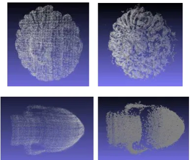
To evaluate the performance of active and passive stereo techniques we considered the number of acquired points and the geometrical error. Tables 2 shows the number of 3D points (Np, Na) acquired for each object with both techniques at each turbidity level (T1, T2, T3, T4), in air and in clear water (CW). As a reference parameter we used the number of points per 100 pixel (ratios Np and Na), measured on the point cloud cleaned through manual removal of the points surrounding the object and noise reduction filtering (Figure 8).
In the Table 3 the percentage of deleted points in the cleaning step is also reported (ratios Npc% and Nac%).
As we can see, for passive stereo the increase of turbidity causes a drastic decrease of acquired points, while for active stereo the reduction of points is less noticeable. It is important to analyze the percentage of point deleted during the preliminary cleaning procedure.
The results show that active stereo technique is more affected by scattering even in light turbidity condition, for this reason a heavy manual deletion of points is needed before using the noise reduction filter that works only on points very close to the object surface. For passive stereo only a light noise reduction filter is needed, but the scattering effect causes a loss of contrast and consequently regions with lack of texture, which may give birth on holes in the final point cloud due to the impossibility of finding correspondent points.
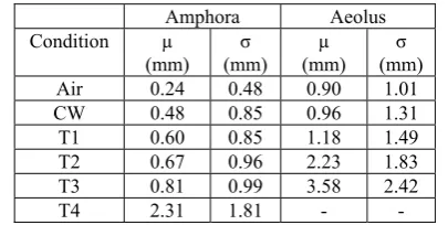
The geometrical error has been evaluated in terms of mean value and standard deviation. We evaluate the errors for each technique separately, first between the point cloud reconstructed in air and the one reconstructed in clear water, then between this latter with the point clouds acquired at each turbidity level (Tables 4 and 5).
As Table 4 and 5 show, there is a slight increase in standard deviation in presence of low and medium turbidity, and at parity of environmental conditions, the discriminant value becomes the material properties: the Aeolus mask shows a higher standard deviation due to its dark texture.
Figure 8: Point clouds at level T1 for active stereo (column left) and passive stereo (column right): the 3D reconstructions
with passive technique shows higher point density but lower filling of surface.
Finally, Table 6 shows that the geometrical error between active and passive stereo techniques increases with turbidity and is higher for the darker Aeolus mask.
Amphora Aeolus
Table 2.: Acquired 3D points per 100 pixel for Aeolus with passive (Np) and active (Na) stereo technique. Npc% and Nac% are the percentage values of deleted points for both techniques.
Amphora Aeolus
Table 3.: Percentage values of deleted 3D points for passive (Npc%) and active (Nac%) stereo techniques.
Amphora Aeolus
Table 4.: Geometrical error (mean µ and standard deviation σ) calculated for active technique: the point clouds are compared respect to a reference (Ref.).
Amphora Aeolus
Table 5.: Geometrical error (mean µ and standard deviation σ) calculated for passive technique: the point clouds are compared respect to a reference (Ref.).
6. CONCLUSIONS
We compare active and passive stereo techniques using a compact and low cost 3D optical system in a laboratory International Archives of the Photogrammetry, Remote Sensing and Spatial Information Sciences, Volume XXXVIII-5/W16, 2011
experimentation conducted in a water tank, with different values of clay concentration to simulate real environment conditions.
Table 6: Geometrical error between point clouds reconstructed with active and passive techniques.
The experiments showed that the two techniques give acceptable results in presence of low an medium turbidity, and each one has pros and cons.
The active technique gives more stable results due to the use of coded patterns to solve the correspondence problem, but the resulting point cloud is affected by a noticeable level of noise due to scattering even in low turbidity, thus requiring more manual operations to clean the point cloud.
The passive technique gives a cleaner and denser point cloud in clear water and low turbidity, but this result is strongly related to the surface texture of the acquired object. As the turbidity increases, evident holes appear in low textured areas. Another difference concerns the time needed for the acquisition phase: the active technique requires the projection of 50 patterns while passive stereo needs only an image pair.
Our equipment uses the same setup and the same calibration for both passive and active stereo technique, so the joint use of both techniques to produce more accurate point clouds will be the blueprint for further researches. The main challenges for future development will be the increase of the performance and the reduction of the acquisition time, by using a lesser number of projected patterns.
REFERENCES
Allais, A.G., Brandou, V., Dentrecolas, S., Gilliotte, J.P., Perrier, M., 2007. Iris - a vision system to reconstruct natural deep-sea scenes in 3D, in: Seventeenth International Offshore and Polar Engineering Conference, Lisbon - Portugal. pp. 111– 118.
Barone, S., Razionale, A.V., 2004. A reverse engineering methodology to capture complex shapes. XVI Congreso Internacional de Ingeniería Gráfica. Saragoza - Spain. pp. 1– 10.
Bouguet, 2011. http://www.vision.caltech.edu/bouguetj/. (accessed 20 January 2011).
Cignoni, P., Montani, C., Scopigno, R., 1997. Computer assisted generation of bas- and high-reliefs. Journal of Graphics Tools, Vol. 2 Issue 3.
Dalgleish, F.R., Tetlow, S., Allwood, R.L., 2004. Laser-assisted vision sensor for AUV navigation. Proc. 14th ISOPE conference, vol. 2, pp. 401-408, May 23-28, Toulon, France.
Drap, P., Scaradozzi, D., Gambogi, P., Long, L., Gauche, F., 2007. Photogrammetry for virtual exploration of underwater archeological sites, in: XXI International Scientific Committee for Documentation of Cultural Heritage (CIPA) Symposium, Athens, Greece.
Edge, M., 2006. Dome port theory. Elsevier Ldt.. Ch. 5. p. 314.
El-Hakim, S.F., Beraldin, J.-A.; Picard, M.; Godin, G.; 2004. Detailed 3D reconstruction of large-scale heritage sites with integrated techniques. Computer Graphics and Applications, IEEE, Vol.: 24 Issue:3; pp. 21 – 29.
Fontana, R., Greco, M., Materazzi, M., Pampaloni, E., Pezzati, L., Rocchini, C., and Scopigno, R. 2002. Three-dimensional modelling of statues: the Minerva of Arezzo, Journal of Cultural Heritage, Vol. 3, Issue 4, pp. 325-331.
Firoozfam, P., Negahdaripour, S., 2003. A multi-camera conical imaging system for robust 3D motion estimation, positioning and mapping from UAVs, in: AVSS ’03: Proceedings of the IEEE Conference on Advanced Video and Signal Based Surveillance, IEEE Computer Society, Washington, DC, USA. p. 99.
Guidi, G., Remondino, F., Russo, M., Menna, F., Rizzi, A., Ercoli, S., 2009. A Multi-Resolution Methodology for the 3D Modeling of Large and Complex Archeological Areas.
International Journal of Architectural Computing, Vol. 7, No. 1, pp. 39-55.
Gupta, M., Narasimhan, S.G., Schechner, Y.Y., 2008. On controlling light transport in poor visibility environments, in:
IEEE Conference on Computer Vision and Pattern Recognition, CVPR 2008., Anchorage, AK. pp. 1–8.
Harvey, E., Shortis, M., 1995. A system for stereo-video measurement of sub-tidal organisms. Marine Technology Society Journal, 29, pp. 10–22.
He, D.M., Seet, G.G.L., 2004. Divergent-beam lidar imaging in turbid water. Optics and Lasers in Engineering, 41, pp. 217– 231.
Hobson, P.R., Watson, J., 2002. The principles and practice of holographic recording of plankton. Journal of Optics A: Pure and Applied Optics 4, S34–S49.
Jaffe, J.S., Dunn, C., 1988. A model-based comparison of underwater imaging systems. Proceedings of the Ocean Optics IX 925, 344–350.
J. S. Jaffe, 1990. Computer modeling and the design of optimal underwater imaging systems, IEEE Journal of Oceanic Engineering 15 (2) pp. 101–111.
Lowe, D.G., 2004. Distinctive image features from scale-invariant keypoints. International Journal of Computer Vision, 60, 2, pp. 91-110.
Leone, A., Diraco, G., Distante, C., 2006. Stereoscopic system for 3D seabed mosaic reconstruction, in: International Conference on Image Processing, ICIP, pp. II541–II544.
Menci, 2011. http://www.menci.com (accessed 20 January 2011).
Meshlab, 2011. http://meshlab.sourceforge.net/ (accessed 20 January 2011).
Moore, K.D., 2001 Intercalibration Method for Underwater Three-Dimensional Mapping Laser Line Scan Systems, Applied Optics, Vol. 40, Issue 33, pp. 5991-6004.
Remondino, F., El-hakim, S., 2006. Image-based 3D modelling: A review. Photogrammetric Record, 21, pp. 269–291.
Roman, C., Inglis, G., Rutter, J., 2010. Application of structured light imaging for high resolution mapping of underwater archaeological sites, in: IEEE Oceans Sydney.
Saito, H., Kawamura, H., Nakajima, M., 1995. 3D shape measurement of underwater objects using motion stereo, in:
IECON Proceedings (Industrial Electronics Conference), pp. 1231–1235.
Salvi, J., Pages, J., Batlle, J., 2004. Pattern codification strategies in structured light systems. Pattern Recognition 37, pp. 827–849.
Scansystems, 2011, http://www.scansystems.it/ (accessed 20 January 2011).
Scharstein, D., and Szeliski, R., 2002. A taxonomy and evaluation of dense two-frame stereo correspondence algorithms. International Journal of Computer Vision, 47(1/2/3): pp.7-42.
Schechner, Y.Y., Karpel, N., 2004. Clear underwater vision, in:
Proceedings of the IEEE Computer Society Conference on Computer Vision and Pattern Recognition, pp. I536–I543.
Unesco, 2001. http://www.unesco.org/en/underwater-cultural-heritage, (accessed 20 January 2011).
Furukawa, Y. and Ponce, J. 2007. Accurate, Dense, and Robust Multi-View Stereopsis. IEEE Computer Society Conference on Computer Vision and Pattern Recognition.
ACKNOWLEDGEMENTS
This work has been partially supported by the Project ”MESSIAH”, financed by APQ MUR-Regione Calabria (POR 2000-2006 Misura 3.16 - DM 593 del 08/08/2000).