EXPLORING THE MOON WITH THE LUNAR RECONNAISSANCE ORBITER
CAMERA
Mark S. Robinsona, Emerson J. Speyerera, Aaron Boyda, Devin Wallera, Robert V. Wagnera , Kyle N. Burnsa a
Arizona State University, School of Earth and Space Exploration, 1100 S Cady, Tempe AZ, 85287 – ([email protected])
Commission IV, WG IV/7
KEY WORDS: High resolution, Planetary, Mapping, Mosaic, DEM/DTM, Imagery, Multispectral, Multitemporal
ABSTRACT:
The Lunar Reconnaissance Orbiter Camera (LROC) consists of three imaging systems: a Wide Angle Camera (WAC) and two Narrow Angle Cameras (NACs). Since entering lunar orbit in June of 2009, LROC has collected over 700,000 images. A subset of WAC images were reduced into a global morphologic basemap, a near-global digital elevation model, and multitemporal movie sequences that characterize illumination conditions of the polar regions. In addition, NAC observations were reduced to meter scale maps and digital elevation models of select regions of interest. These Reduced Data Record (RDR) products were publicly released through NASA’s Planetary Data System to aid scientists and engineers in planning future lunar missions and addressing key science questions.
1. INSTRUMENT OVERVIEW
The Lunar Reconnaissance Orbiter Camera (LROC) system provides synoptic and high resolution imaging of the lunar surface [Robinson et al., 2010]. The Wide Angle Camera (WAC) is a seven band (315, 360, 415, 566, 604, 643, 689nm) push frame imager with a 90° field of view in monochrome mode, and 60° field of view in multispectral mode. From the nominal 50 km polar orbit, the WAC acquires images with a nadir pixel scale of 75 meters for the visible filters (384 meters for the UV filters). The WAC images almost the entire Moon each month, capturing the lunar surface under a variety of lighting conditions over time. This global dataset enables the creation of morphologic maps, near-global digital elevation models (DEMs), and polar illumination movie sequences.
The Narrow Angle Camera (NAC) consists of two line scan cameras that provide high resolution images at a pixel scale of 0.5 to 2.0 meters and a combined field of view of 5.7°. Around summer solstice at each lunar pole, when shadows are at a minimum, hundreds of images are acquired and later reduced into high resolution maps. These NAC polar mosaics extend from the pole out to 85.5° N/S and have a pixel scale of two meters. In addition to polar mosaics, high resolution (pixel scale between 0.5 and 2.0 meters) maps are also created for other regions of interest across the Moon. Finally, NAC stereo observations are also processed into high resolution DEMs. DEMs generated from NAC stereo pairs acquired over many months are processed and mosaicked to create regional terrain models with a pixel scale of two to five meters.
Since entering orbit in 2009, LROC has acquired over 700,000 images WAC and NAC images. A subset of this image collection provides the basis for the production of DEMs and image mosaics over a broad range of spatial scales. LROC images (Experiment Data Records, or EDR) and Reduced Data Record (RDR) products created by the LROC team are publicly released through NASA’s Planetary Data System to aid
scientists and engineers investigating the Moon [Jolliff et al., 2011, Mahanti et al., 2012; Ashley et al., 2012].
2. REDUCED DATA RECORDS
2.1 WAC Global Basemap
The WAC global mosaic is comprised of over 15,000 images acquired between November 2009 and February 2011. The WAC maps the whole Moon in one month, however the solar incidence angle at the equator changes about 28° during a month. To even out the monthly incidence angle variations, the equatorial mosaic is comprised of data collected over three separate periods (1/20/2010 to 1/28/2010, 5/30/2010 to 6/6/2010, 7/24/2010 to 7/31/2010). The south polar mosaic images were acquired 8/10/10 to 9/19/10 and the north polar images 4/22/10 to 5/19/10 (Table 1, Figure 1). Remaining gores were filled with images acquired at other times with similar lighting conditions. The non-polar images were map projected onto the GLD100 (WAC derived 100m/pixel DEM) while polar images were map projected on the LOLA shape model (79° to 90° N/S) and the GLD100 (60° to 79° N/S) [Smith et al, 2010; Scholten et al., 2012]. In addition, the LOLA derived crossover corrected ephemeris and a precise camera pointing model provide accurate positioning of each WAC image (to within a pixel) [Mazarico et al., 2011; Speyerer et al, 2012b]. Because the polar images were acquired at a different season than the equatorial images, and the lunar photometric function is not perfectly known, there is a brightness difference where the polar mosaics meet the equatorial mosaics. In a future release this discontinuity will be reduced.
The WAC global mosaic is archived in ten regional tiles (Table 1) at three different pixel scales to better serve the lunar science community: 100 meters per pixel (mpp), 256 pixels per degree (ppd) and 128 ppd. Eight of the tiles are equirectangular projections that encompass 60° latitude by 90° longitude. In addition, two polar stereographic projections are available for the poles from 60° to 90° north and south, respectively.
International Archives of the Photogrammetry, Remote Sensing and Spatial Information Sciences, Volume XXXIX-B4, 2012 XXII ISPRS Congress, 25 August – 01 September 2012, Melbourne, Australia
Product Name Latitude Longitude Date Beta Angle
Azimuth
WAC_GLOBAL_E300N0450 0° to 60° 0° to 90° 7/24/10 to 7/31/10 60-66 West WAC_GLOBAL_E300S0450 -60° to 0° 0° to 90° 7/24/10 to 7/31/10 60-66 West WAC_GLOBAL_E300N1350 0° to 60° 90° to 180° 1/20/10 to 1/28/10 61-69 West WAC_GLOBAL_E300S1350 -60° to 0° 90° to 180° 1/20/10 to 1/28/10 61-69 West WAC_GLOBAL_E300N2250 0° to 60° 180° to 270° 5/30/10 to 6/6/10 61-69 East WAC_GLOBAL_E300S2250 -60° to 0° 180° to 270° 5/30/10 to 6/6/10 61-68 East WAC_GLOBAL_E300N3150 0° to 60° 270° to 360° 7/30/10 to 8/7/10 55-61 West WAC_GLOBAL_E300S3150 -60° to 0° 270° to 360° 7/30/10 to 8/7/10 53-61 West WAC_GLOBAL_P900N0000 60° to 90° 0° to 360° 4/22/10 to 5/19/10 23-50 - WAC_GLOBAL_P900S0000 -90° to -60° 0° to 360° 8/10/10 to 9/19/10 10-50 -
Table 1. LROC WAC global mosaic tiling scheme (E, P = equirectangular or polar; N, S = north or south).
Figure 1. LROC WAC global mosaic consist of eight equirectangular tiles that encompass 60° latitude by 90° longitude and two polar stereographic tiles that cover 60° to the respective pole.
2.2 WAC DEM and Shaded Relief
Orbit-to-orbit and month-to-month WAC image overlap provides repeat stereo observations for the entire illuminated surface of the Moon enabling production of a near-global DEM. In the 50 km polar orbit, WAC observations offer substantial (~50% at the equator) across-track stereo with images acquired from adjacent orbits. A total of ~69,000 stereo models acquired during the one-year nominal mission and the first months of the science mission phase were combined into a near-global DEM sampled at a pixel scale of 100 meters. This new topographic model map is known as the Global Lunar DEM 100 m topographic model, or "GLD100" [Scholten et al., 2012]. Due to persistent shadows near the poles it is not possible to create a complete WAC stereo map at the very highest latitudes. The GLD100 thus covers from 79° S latitude to 79° N latitude, covering 98% of the lunar surface. Since the stereo correlation box is larger than 100 meters, surface details at the 100-meter scale are not fully resolved. However, each 100-
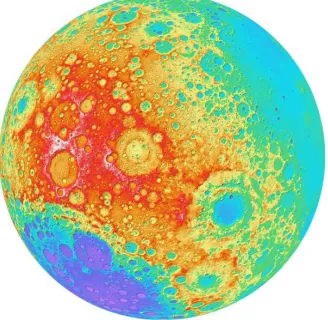
Figure 2. Orthographic view of the WAC Shaded Relief centered at 240° E longitude and 0° latitude.
International Archives of the Photogrammetry, Remote Sensing and Spatial Information Sciences, Volume XXXIX-B4, 2012 XXII ISPRS Congress, 25 August – 01 September 2012, Melbourne, Australia
meter sampling square has an average of 26 stereo points (from multiple months observations; for a planet-wide total of 100 billion points), which sharpens the elevation estimate at that scale. The resolution, in a formal sense, is probably close to 300 meters globally, and the vertical accuracy of the elevations is estimated to be better than 20 meters [Scholten et al., 2012].
The GLD100 is archived in the original 100 meter pixel scale format in ten tiles (identical to that of the WAC mosaic, see table 1). The GLD100 is also available in same tile format for scales of 256 ppd and 128 ppd. Since the LRO orbits converge at the poles, Lunar Orbiter Laser Altimeter (LOLA) provides a very high resolution topographic model of the poles [Smith et al 2010a,b, Zuber et al., 2010]. For the 256 ppd and lower resolution formats the LOLA polar data fills in the WAC "hole at the pole", above and below 79°N and 79°S, respectively.
Shaded relief images were created from the GLD100 by illuminating the surface from a given Sun direction and elevation above the horizon (Figure 2). To convey an absolute sense of height, the resulting shaded relief grayscale pixels were painted with colors that represent the elevation (relative to the mean lunar radius). The GLD100 Color Shaded Relief map is available at 128 ppd in the same tiled format as the GLD100, as well as global files at lesser resolutions. All of the Color Shaded Relief products are available with and without latitude and longitude grids (10° increments).
2.3 WAC Polar Movies
During overpasses of the north and south pole, the WAC images the terrain from 80° poleward to 90° and back to 80° on the night side. With the 90° field of view (in monochrome mode), the WAC provides images with repeat spatial coverage around both lunar poles, which enable the visualization lighting conditions as the Sun progresses across the horizon each lunar day and the sub-solar latitude migrates from 1.5˚ S to 1.5˚ N over a lunar year. This small tilt in the spin axis leaves some areas near the poles in permanent shadow, while other nearby regions remain sunlit for the majority of the year. Theory, radar observations, neutron measurements, and Lunar CRater Observation and Sensing Satellite (LCROSS) experiments suggest that volatiles may be present in cold traps in permanently shadowed regions. While, areas of near permanent illumination are prime locations for future lunar outposts due to their benign thermal conditions and near constant accessibility to solar power.
One of the primary scientific objectives of the Lunar Reconnaissance Orbiter Camera (LROC) is to unambiguously identify regions of permanent shadow and near permanent illumination using its two imaging systems that provide medium and high resolution views of the poles. Since the start of the nominal mission, LROC has acquired over 20,000 Wide Angle Camera (WAC) images of the polar regions. LRO's 50-km polar orbit enables images of each pole to be acquired every ~2 hours during normal spacecraft and instrument operations (average time between WAC observations is 2.3 hours including spacecraft and instrument disturbances). The WAC 90° field of view (monochrome mode) allows for a 104-km region within 2° degrees of the pole to be acquired at a pixel scale of 100 m. This mulitemporal coverage delimits permanently shadowed regions and permanently (or near permanently) illuminated regions over full year (2/16/2010 to 2/16/2011) with time steps every 2.3 hrs (on average) [Speyerer, et al. 2012a]. The polar images were map projected on the LOLA shape model produced in
December 2010 with LOLA derived crossover corrected ephemeris (when available) and an improved camera-pointing model to provide accurate geospatial positioning [Zuber et al., 2010; Mazarico et al., 2012]. As the Moon rotates, LRO's orbital inclination changes slightly, which causes the WAC frames to wander across the poles over time thus slightly reducing the area of complete repeat coverage.
2.4 NAC Polar Mosaics
Due to the tilt of the lunar spin axis noticeable lighting changes occur from lunation to lunation. The polar regions are most illuminated at their respective summer solstice. Thus, a mosaicking campaign was executed for each pole centered on the respective summer solstice (2010-07-23 through 2010-12-11 for the south pole and 2010-1-18 through 2010-6-7 for the north pole). The mosaic has a latitude range of -90° to - 85.5° latitude and is stored as 24 polar stereographic map tiles. The tiles are in latitudinal bands radiating from the pole. There are four tiles in the first band (90° to 88.5° latitude), eight in the second (88.5° to 87° latitude) and twelve in the third (87° to 85.5° latitude) at each pole (N,S).
NAC images were map projected onto the LOLA polar 5 m/pixel DEM using the LOLA crossover corrected ephemeris at a pixel scale of 2 m [Smith et al., 2010; Mazarico et al., 2012]. The images were not registered to one another, and the mapping error between images is on average 7.2 meters in the sample direction and 4.6 meters in the line direction.
2.5 NAC Regional Mosaics DEM) and LOLA derived crossover corrected ephemeris [Scholten et al., 2012; Mazarico et al., 2012]. In some cases images with similar incidence angles have opposite solar azimuth angles (east and west). A local semi-controlled network was then generated to align images into large mosaics of the region. Due to the large size of the NAC mosaics, the pyramidal tiffs were down-sampled by approximately a factor of 4 to 2m/px or 8m/px.
2.6 NAC DEM
LROC NAC DEMs are made from geometric stereo pairs (two images of the same area on the ground, taken from different view angles under nearly the same illumination) [Tran et al., 2010; Burns et al., 2012]. LROC was not designed as a stereo system, but can obtain stereo pairs through images acquired from two orbits (with at least one off-nadir slew). Off-nadir rolls interfere with the data collection of the other instruments, so LROC slew opportunities are limited to four per day. Due to the time-intensive process, not all of the stereo pairs have been made into DEMs.
To generate a DEM, we use a combination of the USGS Integrated Software for Imagers and Spectrometers (ISIS) and SOCET SET from BAE Systems. ISIS routines ingest the image files, perform a radiometric correction, and export to a format SOCET SET accepts. The files imported into SOCET SET are Level 1 radiometrically corrected NAC images and a list of
International Archives of the Photogrammetry, Remote Sensing and Spatial Information Sciences, Volume XXXIX-B4, 2012 XXII ISPRS Congress, 25 August – 01 September 2012, Melbourne, Australia
keywords of relevant parameters, such as spacecraft coordinates, altitude, Euler angles, and ephemeris positions [Tran et al., 2010; Burns et al., 2012].
From the final DEM the following derived products are archived: orthorectified image, shaded relief image, color shaded relief image, color slope map, and confidence map. An orthorectified image has all topographical and camera distortions removed. These images are cartographically true and can be used to measure accurate distances. A shaded-relief generated using the DEM simulates the Moon's surface with a light source casting shadows on the terrain. Color coded elevations are draped on the shaded-relief to form the color shaded relief map. Finally slopes derived from the DEM are color-coded. A confidence map indicates the quality of the elevation estimate at each pixel. Refer to the readme file for the description of the pixel values.
The DEM, orthorectified images, are archived as standard PDS products in two resolutions (resolution of the DEM and resolution of the original images), and the confidence map. The shaded-relief, color shaded-relief, color slope map, and DEM are in GeoTIFF format.
For more information on the methodology and preliminary error analysis of the DEMs [Tran et al. 2010 and Burns et al 2012].
3. REFERENCES
Ashley, J.W., Robinson, M.S., Ray Hawke, B., van der Bogert, C.H., Hiesinger, C., Sato, H., Speyerer, E.J., Enns, A., Wagner, R.V., Young, K., Burns, K.N., 2011. Geology of the King Crater Impact Melt Pond. Journal of Geophysical Research.. Submitted.
Burns, K.N., Speyerer, E.J., Robinson, M.S., Tran, T., Rosiek, M.R., Archinal, B.A., Howington-Kraus, E., and the LROC Science Team, 2012. Digital elevation models and derived products from LROC NAC stereo observations. This volume.
Jolliff, B.L., Wiseman, S.A., Lawrence, S.J., Tran, T., Robinson, M.S., Sato, H.S., Hawke, B.R., Scholten. F., Oberst. J., Hiesinger, H., van der Bogert, C.H., Greenhagen, B.T., Glotch, T.D., Paige, D.A, 2011. Non-mare silicic volcanism on the lunar farside at Compton-Belkovich, Nature Geoscience, 4(8), 566-571.
Mahanti, P., Burns, K., Tran, T., Robinson, M.S., 2012. Measurement of Highland Pond Melt Volumes from LRO NAC DEMs. 43rd Lunar and Planetary Science Conference, Houston, TX, March 2012, Abs #2807.
Mazarico, E., Rowlands, D.D., Neumann, G.A., Smith, D.E., Torrence, M.H., Lemoine, F.G., Zuber, M.T., 2012. Orbit Determination of the Lunar Reconnaissance Orbiter, Journal of Geodesy, 86(3), 193-207.
Robinson, M.S., Brylow, S.M., Tschimmel, M., Humm, D., Lawrence, S.J., Thomas, P.C., Denevi, B.W., Bowman-Cisneros, E., Zerr, J., Ravine, M.A., Caplinger, M.A., Ghaemi, F.T., Schaffner, J.A., Malin, M.C., Mahanti, P., Bartels, A., Anderson, J., Tran, T.N., Eliason, E.M., McEwen, A.S., Turtle, E., Jolliff, B.L., Hiesinger, H., 2010. Lunar Reconnaissance Orbiter Camera (LROC) Instrument Overview. Space Science Reviews, 150, doi 10.1007/s11214-010-9634-2.
Scholten, F., Oberst, J., Matz, K.-D., Roatsch, T., Wählisch, M., Speyerer, E.J., Robinson, M.S., 2012, GLD100: The near-global lunar 100 m raster DTM from LROC WAC stereo image data, Journal of Geophysical Research, 117, doi:10.1029/ 2011JE003926.
Smith, D.E., Zuber, M., Jackson, G.B., Cavanaugh, J.F., Neumann, G.A., Riris, H., Sun, X., Zellar, R.S., Coltharp, C., Connelly, J., Katz, R.B., Kleyner, I., Liiva, P., Matuszeski, A., Mazarico, E.M., McGarry, J.F., Novo-Gradac, A., Ott, M.N., Peters, C., Ramos-Izquierdo, L.A., Ramsey, L., Rowlands, D.D., Schmidt, S., Scott, V.S., Shaw, G.B., Smith, J.C., Swinski, J.P., Torrence, M.H., Unger, G., Yu, A.W., Zagwodzki, T.W., 2010a. The Lunar Orbiter Laser Altimeter Investigation on the Lunar Reconnaissance Orbiter Mission. Space Science Reviews, 150, doi 10.1007/s11214-009-9512-y
Smith, D.E., Zuber, M.T., Neumann, G.A., Lemoine, F.G., Mazarico, E., Torrence, M.H., McGarry, J.F., Rowlands, D.D., Head III, J.W., Duxbury, T.H., Aharonson, O. Lucey, P.G., Robinson, M.S., Barnouin, O.S., Cavanaugh, J.F., Sun, X., Lilva, P., Mao, D., Smith, J.C., Bartels, A.E., 2010b. Initial observations from the Lunar Orbiter Laser Altimeter (LOLA) Geophysical Research Letters, 37, doi:10.1029/2010GL043751.
Speyerer, E.J., Robinson, M.S. 2012. Persistently illuminated regions at the lunar poles: Ideal sites for future exploration,
Icarus, submitted.
Speyerer, E.J., Wagner, R.V., Robinson, M.S., Humm, D.C., Becker, K., Anderson, J., Thomas P., 2012, In-flight geometric calibration of the Lunar Reconnaissance Orbiter Camera. This volume.
Tran, T., Rosiek, M.R., Beyer, R., Mattson, S., Howington-Kraus, A., Robinson, M.S., Archinal, B.A., Edmundson, K. Harbour, D., Anderson, E., and the LROC Science Team, 2010. Generating Digital Terrain Models Using LROC NAC Images, paper presented at International Symposium IV/7 Planetary Mapping and Databases, Institue of Planetary Research, Orland, FL.
Zuber, M.T., Smith, D.E., Zellar, R.S., Neumann, G.A., Sun, X., Katz, R.B., Kleyner, I., Matuszeski, A., McGarry, J.F., Ott, M.N., Ramos-Izquierdo, L. Rowlands, D., Torrence, M.H., Zagwodzki, T.W., 2010. The Lunar Reconnaissance Orbiter Laser Ranging Investigation. Space Science Reviews, 150, doi 10.1007/s11214-009-9511-z.
International Archives of the Photogrammetry, Remote Sensing and Spatial Information Sciences, Volume XXXIX-B4, 2012 XXII ISPRS Congress, 25 August – 01 September 2012, Melbourne, Australia