PHOTOGRAMMETRIC NETWORK FOR EVALUATION OF HUMAN FACES
FOR FACE RECONSTRUCTION PURPOSE
Péter Schrott*, Ákos Detrek i, Károly Fekete
Budapest University of Technology and Economics, Department of Photogrammetry and Geoinformatics M egyetem rkp. 3., 1111 Budapest, Hungary
KEY WORDS: Biometrics, Close Range, Convergent, Networks, Modelling
ABSTRACT:
Facial reconstruction is the process of reconstructing the geometry of faces of persons from skeletal remains. A research group (BME Cooperation Research Center for Biomechanics) was formed representing several organisations to combine knowledgebases of different disciplines like anthropology, medical, mechanical, archaeological sciences etc. to computerize the face reconstruction process based on a large dataset of 3D face and skull models gathered from living persons: cranial data from CT scans and face models from photogrammetric evaluations. The BUTE Dept. of Photogrammetry and Geoinformatics works on the method and technology of the 3D data acquisition for the face models. In this paper we will present the research and results of the photogrammetric network design, the modelling to deal with visibility constraints, and the investigation of the developed basic photogrammetric configuration to specify the result characteristics to be expected using the device built for the photogrammetric face measurements. lifetime, so the morphology of the skull gives an opportunity to estimate the muscular system of the face. Additional aids for the he soft tissue estimation are the so-called median soft tissue datasets. These sets based on statistical measurements of the average soft tissue thickness of the face in several anthropological landmarks. (Kustár, 2004) This statistical method however carries some uncertainty. A multidisciplinary research study has been started in 2007 in the Budapest University of Technology and Economics, which aims to support human morphologic measurements by photogrammetric methods. The goal of our research cooperation is to develop the face reconstruction method and create a face reconstruction software based on statistically sufficient samples (3D face and skull models of persons) and guided by defined mathematical correlations between the anatomy of the skull and the face geometry.
The first phase of the project is targeted at finding the optimal measuring technology to collect geometric data of the human face. Medical imaging is a continuously developing science, and nowadays we can choose from several possibilities. We have reviewed some of them, and made an accuracy analysis of them, the results were published in the ISPRS XXI. Congress, Beijing, 2008. (Schrott, 2008.) These results suggested that for obtaining cranial data the only viable option is to use CT scans. Even though the soft tissues absorbs X-rays to a lesser extent, the geometric precision of the 3D model is only slightly lower than in the case of bony structures, therefore theoretically we can gain 3D model of the face by CT. The reason we chose another method was that all of the CT devices we know works on lying persons facing upwards. This position causes the face distorted by gravity which in this case takes effect in different direction as usual. In special occasions (elderly or overweight
persons), the difference of the face of a standing or lying person can be so large that the person is virtually unrecognizable. Investigation of other possibilities result in the decision of using photogrammetry, the high accuracy required by the anthropologist experts can be achieved by this.
2. NETWORK DESIGN
Non-topographic applications of photogrammetry rarely uses stereoscopic image pairs for evaluation, using a convergent photogrammetric network can result in more accurate measurements. Hence, several parameters (like the number of cameras, the geometry and arrangement of them etc.) can be adjusted more freely to optimize the measurement. The development of the photogrammetric capturing device required the calculation and the design of this subject-specific the required measurement quality (reliability and precision) by finding a suitable set of measurements with the least possible cost. It is widely accepted that the First Order Design (FOD) of the close range photogrammetric network is to adapt the network for the network design constraints, followed by an iterative simulation of the network. (Fraser, 1996) (Fekete 2006)
2.1 Incident and intersecting angle constraints
The viewing direction and the surface normal at the feature highly affect the reliability of the measurement: perpendicular is the optimal arrangement, from directions close to coplanar are the worst. The other angle-specific problem is the intersecting angles of the camera’s optical axles; each perpendicular to another is desirable. One of the most widespread network architecture in close range photogrammetry is a square-based
International Archives of the Photogrammetry, Remote Sensing and Spatial Information Sciences, Volume XXXIX-B3, 2012 XXII ISPRS Congress, 25 August – 01 September 2012, Melbourne, Australia
equilateral-triangle sided pyramid, with the object to be measured in the top and the cameras at the other vertices. This arrangement ensures low and evenly distributed errors. We decided to use a slightly modified version of this arrangement. (Figure 1. Mason, 1995)
Figure 1. Multi station convergent network (Mason, 1995)
2.2 Visibility constraint
One of the most important constraint of the network design is the visibility constrain. The problem in an image-based framework, in which we use a limited number of images of an object taken from unknown viewpoints to determine which subsets of features can be simultaneously visible in other views. This constraint highly affects the positions and the directions of the cameras.
The nature of the face measurement inflicts that occlusions caused by external objects are not need to be dealt with, however some parts of the face mask another parts itself. The most significant obstructions are caused by the chin and the nose. The four cameras will ensure that all parts of the face will appear in at least two images, but in order to increase the accuracy a setting should choose where the greater proportion of the points are displayed in three (or possibly four) images. A visibility modelling was performed to determine the ideal spatial arrangement of the cameras.
Visibility modelling
The visibility modelling requires a 3D model or models of faces. Obviously, the parameters of the 3D model affect the result of the modelling. Ideally every face should be captured in a photogrammetric network optimized for that particular person, but it is not feasible, one arrangement should be chosen which works for the most faces acceptably.
V. Blanz and T. Vetter (Blanz, 1999) designed a morphable face model based on the statistics of 3D laser scans of 200 people.This model can be changed not only by mathematical parameters (size, angle, etc) but by more “humane” parameters, like age, sex or mood. The Singular Inversions FaceGen Modeller software uses this morphable irregular polygon model, and we generated an “average” face with this software for the visibility modelling. (Figure 2.) The generated model was adjusted further for our purpose by a 3D modelling software (Blender), in consideration of a former study of the optimal point density and arrangement described in (Varga, 2008).
Figure 2. Morphable face model
This modelling software was used to simulate the camera parameters (viewing angle, focal length, subject distance etc.) The face model consist of approx. 6000 vertices, the aim of the modelling was to calculate the visible subset of these points from different angles. The method was simple: the face model was rotated in front of the camera and the rendered camera images were inspected. (Figure 3.)
Figure 3. Visibility modelling in Blender
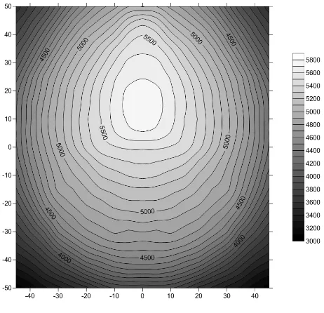
The centre of the rotation was the intersection of the Coronal, Traverse and Sagittal planes. The rotation angles were 100° in 20 steps in both horizontally and vertically. The modelling process resulted a visibility isoline map, showing the number of visible vertices from a particular camera position. (Figure 4.) The contour lines show the number of visible vertices, the axes show the camera direction from the frontal position in degrees.
Figure 4. Visibility map.
International Archives of the Photogrammetry, Remote Sensing and Spatial Information Sciences, Volume XXXIX-B3, 2012 XXII ISPRS Congress, 25 August – 01 September 2012, Melbourne, Australia
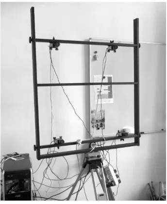
The camera positions can be shown in this map as the corners of a square – the size of the square defines the distance between the cameras, and also the intersecting angles of the cameras optical axes. Defining the optimal size and position of this rectangle requires further calculations, but this visibility map greatly helped the design of the camera stand and mount.
Figure 5. Adjustable camera mount
3. DEFINING PARAMETERS OF THE MOBILE TEST FIELD BASE NETWORK
The concept of the basic configuration of close range photogrammetry networks was introduced by Mason. The concept essentially means that photogrammetrists develop readily usable photography and processing methods for various task types (networks) occurring in practice and also specify the result characteristics to be expected. We extended the set of basic network types with the type of the mobile test-field of photogrammetric measurement for face reconstruction and specified the function describing the design factor q, characteristic of this network. We specified this value in function of the average error of scale and image coordinates. A measuring field with calibrated control points and the calibration of the cameras are necessitated by the task. A close-range photogrammetric test field was built; it consists of cylinders of various heights mounted on an alloy plate (“manhattan-type”), where the points specified are represented by the holes located on the cover circles of the cylinders. The geometric features of the test field were determined by a Zeiss Opton 3D coordinate measuring machine. This instrument specifies the coordinates of vertices with sharpness within the 0.1 micron range and median error of less than one micron. The overall precision of a photogrammetric capturing device depends on the networking aspects. As we chose a convergent, multi-station photogrammetric network, an initial indicator of the precision of triangulation in is given by the formulae
q = design factor expressing the strength of the basic camera station configuration k = number of exposures at each camera station,
a
σ = angular measurement resolution
σ= image coordinate standard error
Given the assumption of k=1 (no redundancy by multiple exposures) the equation (1) can be rewritten as:
q = c/( S) (2)
Equation (2) shows that knowing the image coordinate standard error, the q factor of a network can be given by the object space coordinate RMS deducted from experimental error.
To get experimental errors, a smaller manhattan-type test field was placed into the actual one. (figure 6)
Figure 6. Test fields
This smaller test field was measured by the same coordinate measuring instrument, hence the coordinates are known at one micron precision. The known points of this smaller test field were measured by the photogrammetric capturing device, and the difference between the known and measured points gave us the experimental error. The measurement has been carried out with a Direct Linear Transformation-based Software developed by our Department (Molnar, 2010). The RMS error of this photogrammetric network from 20 measured points was 0.48 mm, so the q factor of this mobile test-field with the described arrangement can be given as:
q = 480 / ( S) (3)
where the precision of the image coordinates are given in µm.
4. CONCLUSION
At this stage of our project, the aim of our work was to develop and build a capturing device for photogrammetric face measurements considering the photogrammetric network design factors. Investigation of the network design constraints resulted that we chose a four-station convergent photogrammetric network. Visibility modelling was performed to be able to define the main parameters of the camera stand and the resulted
International Archives of the Photogrammetry, Remote Sensing and Spatial Information Sciences, Volume XXXIX-B3, 2012 XXII ISPRS Congress, 25 August – 01 September 2012, Melbourne, Australia
visibility map give the possibility to optimize the network further. An accuracy investigation of this photogrammetric network was performed to specify the result characteristics to be expected using this device. The design factor of this close range photogrammetric basic configuration was given as function of the scale and the average error of image coordinates.
REFERENCES
Blanz, V., Vetter, T., 1999. A Morphable Model For The Synthesis Of 3D Faces. SIGGRAPH '99 Proceedings of the 26th annual conference on Computer graphics and interactive techniques. ACM Press/Addison-Wesley Publishing Co. New York, pp. 187-194.
Fekete, K. 2006., Hálózattervezési kérdések a közel-fotogrammetriában. Geodézia és Kartográfia, Budapest, III,pp. 12-23.
Fraser, C. S., 1984, Network design considerations for non-topographic photogrammetry, Photogrammetric Engineering & Remote Sensing, 50, pp. 1115-1126
Fraser, C.S., 1996. Network Design. In: Atkinson, K.B. (Ed.). Close Range Photogrammetry and Machine Vision, Whittles Publishing UK, pa 371, pp. 256-280
Kustár, Á., 2004. Humán morfológiai variációk az arcon és a koponyán. - A koponya és az arc morfológiai
összefüggéseinek alkalmazása a plasztikus
arcrekonstrukcióban. PhD dissertation, pp. 134
Mason, S. O., 1995. Conceptual Model Of The Convergent Multistation Network Configuration Task. The Photogrammetric Record, 15. pp. 277–299
Molnar, B., 2010. Direct Linear Transformation Based Photogrammetry Software on the Web. International Archives of Photogrammetry and Remote Sensing XXXVIII:(5) pp. 462-465. Paper 130.
Schrott, P. Szabó, Gy., Fekete, K., 2008. Data Acquisition Possibilities for face Reconstruction Purpose. International
Archives of Photogrammetry and Remote Sensing
XXXVII:(B5) pp. 817-822. (2008)
Varga, E., Heged s, I., Földváry, L., 2008., Optimalization of density and distribution of stereophotograph measurement points for a face. Proceedings of the Third Hungarian
Conference on Biomechanics. Research Center for
Biomechanics, Budapest, pp. 387-394.
ACKNOWLEDGEMENTS
The research work is funded by the Hungarian Scientific Research Fund (OTKA no. 73251)
International Archives of the Photogrammetry, Remote Sensing and Spatial Information Sciences, Volume XXXIX-B3, 2012 XXII ISPRS Congress, 25 August – 01 September 2012, Melbourne, Australia